1993 CHEVROLET DYNASTY remote control
[x] Cancel search: remote controlPage 740 of 2438
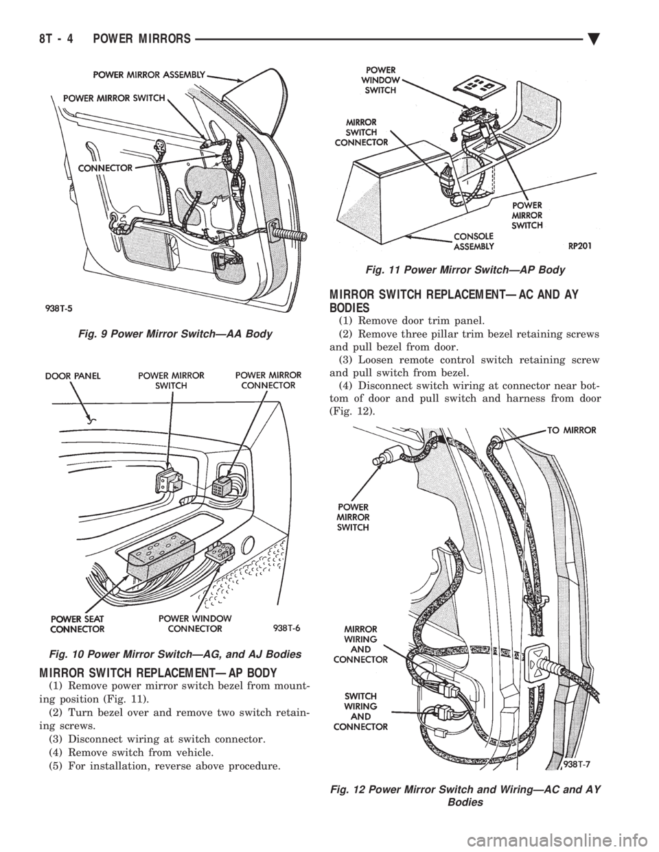
MIRROR SWITCH REPLACEMENTÐAP BODY
(1) Remove power mirror switch bezel from mount-
ing position (Fig. 11). (2) Turn bezel over and remove two switch retain-
ing screws. (3) Disconnect wiring at switch connector.
(4) Remove switch from vehicle.
(5) For installation, reverse above procedure.
MIRROR SWITCH REPLACEMENTÐAC AND AY
BODIES
(1) Remove door trim panel.
(2) Remove three pillar trim bezel retaining screws
and pull bezel from door. (3) Loosen remote control switch retaining screw
and pull switch from bezel. (4) Disconnect switch wiring at connector near bot-
tom of door and pull switch and harness from door
(Fig. 12).
Fig. 9 Power Mirror SwitchÐAA Body
Fig. 10 Power Mirror SwitchÐAG, and AJ Bodies
Fig. 11 Power Mirror SwitchÐAP Body
Fig. 12 Power Mirror Switch and WiringÐAC and AY Bodies
8T - 4 POWER MIRRORS Ä
Page 934 of 2438
Wiring Diagram
Name Sheet Number
Dome Lamp ..............................73
Front Reading Lamps .........................75
Illuminated Visor Vanity Lamps ..................73
Left Front Door Courtesy Lamp ..................76
Left Front Door Jamb Switch ....................75
Left Rear Door Courtesy Lamp ...................76
Left Rear Door Jamb Switch ....................76
Left Lamp Switch ...........................75
Overhead Console ...........................73
Right Front Door Courtesy Lamp .................76
Right Front Door Jamb Switch ...................74
Right Rear Door Courtesy Lamp ..................76
Right Rear Door Jamb Switch ...................73
Transmission Range Indicator Lamp ...............76
Power Assist System ..........................67
Power Door Interlock System ....................106
Power Door Lock Inhibit Relay ...................106
Power Door Lock System .................... .85, 86
Connectors and Door Lock Switch Function ........85, 86
Left Front Door Lock Motor .....................85
Left Front Door Lock Switch ....................85
Left Rear Door Lock Motor .....................85
Right Front Door Lock Motor ....................86
Right Front Door Lock Switch ...................86
Right Rear Door Lock Motor ....................86
Power Remote Heated Mirrors ..................79, 80
Heated Mirror .......................... .79, 80
Left Power Mirror ...........................79
Right Power Mirror ..........................80
Switch ..................................79
Switch Function ............................79
Powertrain Control Module (PCM) .....12, 13, 14, 15, 16, 17,
18, 19, 20, 21, 22, 23, 24, 25, 27, 28, 29, 30, 31, 59
Powertrain Control Module Flex Fuel Connector (2.5L Engine) ............................ .125
Powertrain Control Module Connector (2.5L) ...........108
Powertrain Control Module Connector (3.0L) .......109, 110
Power Window Connector and Switch Functions .........83
Power Window System ..................... .81, 82
Left Front Door Window Lift Master Switch ...........81
Left Front Window Regulator Motor ...............81
Left Rear Window Regulator Motor ................81
Left Rear Door Window Lift Switch ................81
Right Front Window Regulator Motor ...............82
Right Front Door Window Lift Switch ...............82
Right Rear Window Regulator Motor ...............82
Right Rear Door Window Lift Switch ...............82
Radiator Fan Motor ........................ .32, 33
Rear End Lighting (Chrysler/Dodge) with Lamp Outage ....................... .99, 100, 101, 102
Cargo Lamp ............................. .100
Center High Mounted Stop Lamp ................102
Lamp Outage Module .........................99
Left Back-Up Lamp ........................ .102
Left Side Marker Lamp ...................... .102
Left Tail/Stop and Turn Lamp ...................102
License Lamp ............................ .102Wiring Diagram
Name Sheet Number
Right Back-Up Lamp ....................... .102
Right Side Marker Lamp ..................... .102
Right Tail/Stop and Turn Lamp ..................102
Rear End Lighting (Chrysler/Dodge) without Lamp Outage ..................... .103, 104, 105
Center High Mounted Stop Lamp ................105
Left Back-Up Lamp ........................ .103
Left Side Marker Lamp ...................... .103
Left Tail/Stop and Turn Lamp ...................103
License Lamp ............................ .104
Right Back-Up Lamp ....................... .105
Right Side Marker Lamp ..................... .105
Right Tail/Stop and Turn Lamp ..................105
Rear End Lighting (Plymouth) with Lamp Outage ......................... .95, 96, 97, 98
Cargo Lamp ..............................96
Center High Mounted Stop Lamp .................98
Lamp Outage Module .........................95
Left Back-Up Lamp ..........................98
Left Side Marker Lamp ........................98
Left Tail/Stop and Turn Lamp ....................98
License Lamp .............................98
Right Back-Up Lamp .........................98
Right Side Marker Lamp .......................98
Right Tail/Stop and Turn Lamp ...................98
Rear End Lighting (Plymouth) without Lamp Outage ............................ .92, 93, 94
Center High Mounted Stop Lamp .................94
Left Back-Up Lamp ..........................93
Left Side Marker Lamp ........................93
Left Tail/Stop and Turn Lamp ....................93
License Lamp .............................93
Right Back-Up Lamp .........................94
Right Side Marker Lamp .......................94
Right Tail/Stop and Turn Lamp ...................94
Relay Bank ............................... .107
Relays ABS Pump Motor Relay .......................41
ABS System Relay ..........................43
ABS Warning Lamp Relay ......................43
A/C Compressor Clutch Relay .................32, 33
Automatic Shut-down Relay ...............14, 20, 28
Back-Up Lamp Relay .........................37
Engine Starter Relay ........................9,10
Fan Control Relay ....................... .32, 33
Fog Lamp Relay ............................48
Fuel Pump Relay ...........................70
Horn Relay ...............................65
Power Door Lock Inhibit Relay ..................106
Safety Shut-down Relay .......................35
Speaker Relay (NBS) .........................89
Time Delay Relay ...........................54
Seat Belt Warning System .................... .45, 46
Cigar Lighter ..............................45
Headlamp Switch Connector ....................46
Key-in Switch .............................46
Left Front Door Jamb Switch ....................46
8W - 184 WIRING DIAGRAMS AA-BODY Ä
Page 1067 of 2438
Wiring Diagram
Name Sheet Number
Blower Slide Control .........................51
Illumination Lamp ...........................51
Resistor .................................51
Horn System ............................ .63, 64
Clockspring ...............................63
Horn (Hi-note) .............................63
Horn (Lo-note) .............................63
Horn Relay ...............................63
Horn Switch ..............................63
Idle Air Control Motor .................... .14, 21, 26
Ignition Switch .............................4,11
Injectors ............................ .15, 20, 24
Illuminated Entry System ........................91
Left Front Door Courtesy Lamp ..................91
Left Front Door Illuminated Entry Switch ............91
Right Front Door Courtesy Lamp .................91
Right Front Door Illuminated Entry Switch ...........91
Instrument Panel to Multi-Function Switch Wiring .......180
Instrument Panel Ground System ...................86
Interface Grommet ............................58
Intermittent Wiper System .................... .61, 62
Intermittent Wiper Motor ......................62
Intermittent Wiper Switch ......................61
Washer Pump Motor .........................61
Windshield Washer Low Fluid Level Sensor ...........61
Key Cylinders .......................... .131, 135
Key-In Switch .......................... .104, 107
Keyless Entry Connectors ...................... .208
Lamp Outage Module ...................... .96, 209
Lamps Ash Receiver Lamp ........................ .111
Back-Up Lamps ................ .161, 162, 163, 164
Center High Mounted Stop Lamp ......161, 162, 163, 164
Cornering Lamp Left ...............74, 77, 80, 82, 84
Cornering Lamp Right ..............73, 75, 78, 81, 83
Courtesy Lamps ................... .87, 88, 89, 90
Deck Lid Ajar Warning Lamp ....................95
Door Ajar Lamps ...........................95
Door Courtesy Lamp ................ .87, 88, 90, 91
Glove Box Lamp .......................... .111
Halo Lamp .......................... .104, 106
Headlamp-Left ............... .70, 72, 74, 80, 82, 84
Headlamp-Right ............ .69, 71, 73, 75, 78, 81, 83
Headlamp Switch Lamp .......................85
Illuminated Entry Lamps .......................91
Illumination Lamp ..................... .51, 53, 55
License Lamp .................. .161, 162, 163, 164
Low Engine Oil Pressure Lamp .............30, 31, 32
Low Windshield Washer Fluid Warning Lamp .........95
Parking/Turn Lamp-Left ........70, 72, 74, 77, 80, 82, 84
Parking/Turn Lamp-Right .......69, 71, 73, 75, 78, 81, 83
Park Lamp-Left ............................74
Park Lamp-Right ...........................73
Reading Lamps ............................90
Security Lamp ..................... .128, 132, 136
Side Marker Lamp-Left Front ............70, 72, 82, 84
Side Marker Lamp-Right Front ...........69, 71, 81, 83Wiring Diagram
Name Sheet Number
Side Marker Lamp-Left Rear ................161, 163
Side Marker Lamp-Right Rear ...............162, 164
Tail, Stop/Turn Signal Lamp-Left Rear ..........161, 163
Tail, Stop/Turn Signal Lamp-Right Rear .........162, 164
Transmission Range Lamp .....................85
Trunk Lamp ...............................90
Turn Signal Lamp-Left Front ...............74, 77, 80
Turn Signal Lamp-Right Front ..............73, 75, 78
Underhood Lamp ......................... .159
Vanity Mirror ..............................89
Visor Lamp ...............................89
Left Body to Instrument Panel Wiring ............190, 191
Left Front Door Jamb Switch .....................87
Left Rear Door Jamb Switch ......................87
MAP Sensor .......................... .18, 21, 26
Mechanical Cluster Printed Circuit Board .............167
Mechanical Cluster Printed Circuit Board Connectors ......166
Memory Power Seat & Mirror Connector .............204
Memory Power Seat System ...........151, 152, 153, 154
Circuit Breaker ........................... .153
Left Power Seat Motors ..................... .153
Left Power Seat Switch ...................... .152
Left Power Seat Switch Insulator ................152
Left Recliner Motor ........................ .154
Memory Module ................ .151, 152, 153, 154
Recliner Position Sense Resistor .................154
Recliner Seat Switch ....................... .152
Relay Bank ............................. .153
Seat Memory Selector Switch ...................151
Seat Track Position Sense Resistor ...............154
Memory Power Seat System Connectors .............205
Message Center Connector ..................... .207
Mirror-Heated ....................... .143, 144, 146
Mirror-Power .................... .143, 144, 145, 146
Modules Airbag System Diagnostic Module .................57
Air Suspension Control Module ................41, 43
ATC Power Module ........................ .115
Daytime Running Lamp Module ...........72, 76, 79, 84
Lamp Outage Module .................... .96, 209
Mirror Memory Module .................. .143, 144
Power Seat Memory Module .........151, 152, 153, 154
Powertrain Control Module ........14, 15, 16, 17, 18, 19,
20, 21, 22, 23, 24, 25, 26, 27, 28, 29, 37
Relay Module ............................ .171
Remote Keyless Entry Module ...............141, 142
Security Alarm Module ......127, 128, 129, 130, 131, 132,
133, 134, 135, 136, 137, 138
Sunroof Control .......................... .147
Transmission Control Module ...............33, 34, 35
Motors ABS Pump Motor ...........................46
Antenna Motor ........................... .118
Blower-A/C ............................ .53, 55
Blower ATC ............................. .115
Blower-Heater .............................51
Compressor Motor ....................... .40, 42
Ä WIRING DIAGRAMS AC-AY BODY 8W - 317
Page 1069 of 2438
Wiring Diagram
Name Sheet Number
Left Side Marker Lamp ...................... .163
Right Back-Up Lamp ....................... .164
Right Center High Mounted Stop Lamps ............164
Right Inboard Tail, Stop & Turn Signal Lamp .........164
Right License Lamp ........................ .164
Right Outboard Tail, Stop & Turn Signal Lamp ........164
Right Side Marker Lamp ..................... .164
Recliner Position Sense Resistor ..................154
Relay Bank ............................... .171
Relay Module ............................. .171
Relays ABS System Relay ..........................47
A/C Compressor Clutch .................54, 56, 113
Air Suspension .............................42
Automatic Shut Down .................. .15, 23, 29
Automatic Load Leveling .......................40
Back-Up Lamp .............................33
Door Lock/Unlock ......................... .140
Engine Starter .......................... .12, 13
Fan Control ............................. .114
Fuel Pump ...............................36
Horn ...................................63
Headlamp ................................68
Headlamp Door ............................68
Park Lamp .............................. .125
Power Antenna/Name Brand Speaker Relay ..........118
Pump and Motor Relay .......................46
Radiator Fan Control Relay A/C ................54, 56
Radiator Fan Relay ATC ..................... .114
Radiator Fan Relay-Heater ......................52
Safety Shut Down ...........................35
Yellow Lamp Relay ..........................49
Remote Keyless Entry ..................... .141, 142
Program Module .......................... .141
Remote Keyless Entry Module ...............141, 142
Right Body to Instrument Panel Wiring ...........192, 193
Right Front Wheel Sensor .......................50
Right Rear Wheel Sensor ........................50
RS Amplifier ........................... .122, 123
Safety Shut Down Relay ........................35
Seat Belt Warning System .......................67
Seat Belt Switch .............................67
Seat Track Position Sense Resistor .................154
Security Alarm Module Connector (Elec Cluster) ........202
Security Alarm Module Connector (Mech Cluster) ........203
Security Alarm System (Electronic Cluster) ........135, 136,
137, 138
Deck Lid Key Cylinder ...................... .135
Data Link Connector ....................... .136
Left Door Key Cylinder ...................... .135
Relay Bank ............................. .138
Relay Module ............................ .137
Right Door Key Cylinder ..................... .135
Security Alarm Hood Switch ...................136
Security Alarm Module .............135, 136, 137, 138
Security Lamp ........................... .136Wiring Diagram
Name Sheet Number
Security Alarm System (Mech Cluster w/VMC) ......127, 128,
129, 130
Deck Lid Key Cylinder ...................... .127
Data Link Connector ....................... .130
Left Door Key Cylinder ...................... .127
Relay Bank ............................. .130
Relay Module ............................ .129
Right Door Key Cylinder ..................... .127
Security Alarm Hood Switch ...................128
Security Alarm Module .............127, 128, 129, 130
Security Lamp ........................... .128
Security Alarm System (Mech Cluster w/o VMC) . . . .131, 132,
133, 134
Deck Lid Key Cylinder ...................... .131
Data Link Connector ....................... .134
Left Door Key Cylinder ...................... .131
Relay Bank ............................. .134
Relay Module ............................ .133
Right Door Key Cylinder ..................... .131
Security Alarm Hood Switch ...................132
Security Alarm Module .............131, 132, 133, 134
Security Lamp ........................... .132
Sensors Airbag Sensor .............................58
Ambient Sensor .......................... .117
Brake Fluid Level Sensor ......................98
Camshaft Position Sensor ......................28
Coolant Level Sensor .........................98
Crankshaft Position Sensor .....................28
Engine Coolant Temperature Sensors ..........17, 19, 25
Engine Oil Level Sensor .................... .31, 32
Heated Oxygen Sensors ................. .14, 19, 25
Height Sensors ............................44
In Car Senso r............................ .115
Left Front Wheel Sensor .......................50
Left Rear Wheel Sensor .......................50
MAP Sensors ........................ .18, 21, 26
Right Front Wheel Sensor ......................50
Right Rear Wheel Sensor ......................50
Sun Sensor ............................. .115
Throttle Position (Sensors) ................18, 21, 26
Transmission Output Speed Sensor ................34
Turbine Speed Sensor ........................34
Vehicle Speed Sensor .................. .17, 19, 25
Water Sensor ............................ .117
Windshield Washer Low Fluid Level Sensor ...........61
Solenoids Air Exhaust-Automatic Load Leveling Solenoid .........42
Air Suspension Solenoid ................... .41, 44
Deck Lid Release Solenoid ................... .159
EVAP/Purge Solenoids .................. .15, 20, 27
Exhaust Gas Recirculation Solenoids ..........14, 21, 26
Transmission Solenoid .................... .12, 35
Transmission TCC LU Solenoid ..................12
Splices Splice A1 ...........................4,6,8,10
Splice A3 .........................2,37,59,66
Splice A3-1 .....................2,6,8,10,69,71
Ä WIRING DIAGRAMS AC-AY BODY 8W - 319
Page 1287 of 2438
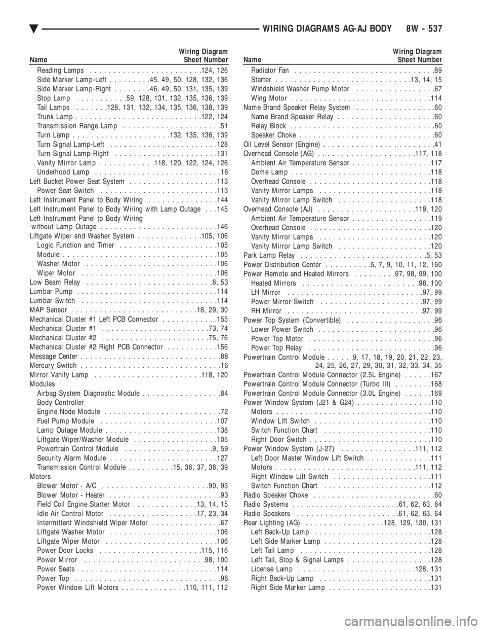
Wiring Diagram
Name Sheet Number
Reading Lamps ....................... .124, 126
Side Marker Lamp-Left .........45, 49, 50, 128, 132, 136
Side Marker Lamp-Right ........46, 49, 50, 131, 135, 139
Stop Lamp .......... .59, 128, 131, 132, 135, 136, 139
Tail Lamps .......128, 131, 132, 134, 135, 136, 138, 139
Trunk Lamp .......................... .122, 124
Transmission Range Lamp .....................51
Turn Lamp .................... .132, 135, 136, 139
Turn Signal Lamp-Left ...................... .128
Turn Signal Lamp-Right ..................... .131
Vanity Mirror Lamp ............118, 120, 122, 124, 126
Underhood Lamp ...........................16
Left Bucket Power Seat System ...................113
Power Seat Switch ........................ .113
Left Instrument Panel to Body Wiring ...............144
Left Instrument Panel to Body Wiring with Lamp Outage . . .145
Left Instrument Panel to Body Wiring without Lamp Outage ........................ .146
Liftgate Wiper and Washer System ..............105, 106
Logic Function and Timer .................... .105
Module ................................ .105
Washer Motor ........................... .106
Wiper Motor ............................ .106
Low Beam Relay ...........................6,53
Lumbar Pump ............................. .114
Lumbar Switch ............................ .114
MAP Sensor .......................... .18, 29, 30
Mechanical Cluster #1 Left PCB Connector ............155
Mechanical Cluster #1 ...................... .73, 74
Mechanical Cluster #2 ...................... .75, 76
Mechanical Cluster #2 Right PCB Connector ...........156
Message Center ..............................88
Mercury Switch ..............................16
Mirror Vanity Lamp ...................... .118, 120
Modules Airbag System Diagnostic Module .................84
Body Controller
Engine Node Module .........................72
Fuel Pump Module ........................ .107
Lamp Outage Module ....................... .138
Liftgate Wiper/Washer Module ..................105
Powertrain Control Module ...................9,59
Security Alarm Module ...................... .127
Transmission Control Module ..........15, 36, 37, 38, 39
Motors Blower Motor - A/C ...................... .90, 93
Blower Motor - Heater ........................93
Field Coil Engine Starter Motor ..............13, 14, 15
Idle Air Control Motor .................. .17, 23, 34
Intermittent Windshield Wiper Motor ...............67
Liftgate Washer Motor ...................... .106
Liftgate Wiper Motor ....................... .106
Power Door Locks ..................... .115, 116
Power Mirror ......................... .98, 100
Power Seats ............................ .114
Power Top ...............................96
Power Window Lift Motors ..............110, 111, 112Wiring Diagram
Name Sheet Number
Radiator Fan ..............................89
Starter ............................ .13, 14, 15
Windshield Washer Pump Motor .................67
Wing Motor ............................. .114
Name Brand Speaker Relay System .................60
Name Brand Speaker Relay .....................60
Relay Block ...............................60
Speaker Choke .............................60
Oil Level Sensor (Engine) ........................41
Overhead Console (AG) .................... .117, 118
Ambient Air Temperature Sensor .................117
Dome Lamp ............................. .118
Overhead Console ......................... .118
Vanity Mirror Lamps ....................... .118
Vanity Mirror Lamp Switch ................... .118
Overhead Console (AJ) .................... .119, 120
Ambient Air Temperature Sensor .................119
Overhead Console ......................... .120
Vanity Mirror Lamps ....................... .120
Vanity Mirror Lamp Switch ................... .120
Park Lamp Relay ...........................5,53
Power Distribution Center ..........5,7,9,10,11,12,160
Power Remote and Heated Mirrors .........97, 98, 99, 100
Heated Mirrors ........................ .98, 100
LH Mirror ............................ .97, 99
Power Mirror Switch ..................... .97, 99
RH Mirror ............................ .97, 99
Power Top System (Convertible) ...................96
Lower Power Switch .........................96
Power Top Motor ...........................96
Power Top Relay ...........................96
Powertrain Control Module ......9,17,18,19,20,21,22,23,
24, 25, 26, 27, 29, 30, 31, 32, 33, 34, 35
Powertrain Control Module Connector (2.5L Engine) ......167
Powertrain Control Module Connector (Turbo III) ........168
Powertrain Control Module Connector (3.0L Engine) ......169
Power Window System (J21 & G24) ................110
Motors ................................ .110
Window Lift Switch ........................ .110
Switch Function Chart ...................... .110
Right Door Switch ......................... .110
Power Window System (J-27) ................111, 112
Left Door Master Window Lift Switch ..............111
Motors ............................. .111, 112
Right Window Lift Switch .................... .111
Switch Function Chart ...................... .112
Radio Speaker Choke ..........................60
Radio Systems ...................... .61, 62, 63, 64
Radio Speakers ..................... .61, 62, 63, 64
Rear Lighting (AG) ................ .128, 129, 130, 131
Left Back-Up Lamp ........................ .128
Left Side Marker Lamp ...................... .128
Left Tail Lamp ........................... .128
Left Tail, Stop & Signal Lamps ..................128
License Lamp ........................ .128, 131
Right Back-Up Lamp ....................... .131
Right Side Marker Lamp ..................... .131
Ä WIRING DIAGRAMS AG-AJ BODY 8W - 537
Page 1701 of 2438
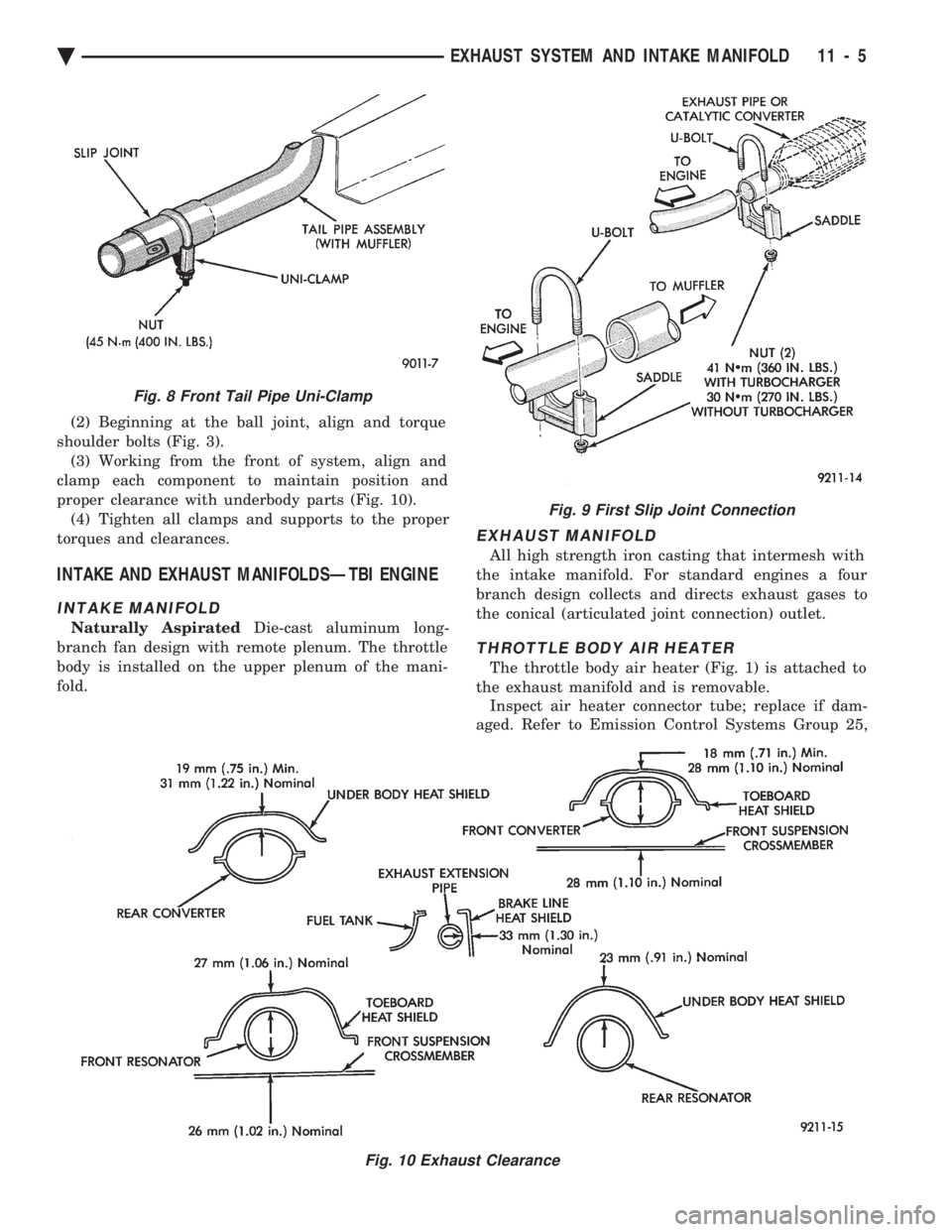
(2) Beginning at the ball joint, align and torque
shoulder bolts (Fig. 3). (3) Working from the front of system, align and
clamp each component to maintain position and
proper clearance with underbody parts (Fig. 10). (4) Tighten all clamps and supports to the proper
torques and clearances.
INTAKE AND EXHAUST MANIFOLDSÐTBI ENGINE
INTAKE MANIFOLD
Naturally Aspirated Die-cast aluminum long-
branch fan design with remote plenum. The throttle
body is installed on the upper plenum of the mani-
fold.
EXHAUST MANIFOLD
All high strength iron casting that intermesh with
the intake manifold. For standard engines a four
branch design collects and directs exhaust gases to
the conical (articulated joint connection) outlet.
THROTTLE BODY AIR HEATER
The throttle body air heater (Fig. 1) is attached to
the exhaust manifold and is removable. Inspect air heater connector tube; replace if dam-
aged. Refer to Emission Control Systems Group 25,
Fig. 9 First Slip Joint Connection
Fig. 10 Exhaust Clearance
Fig. 8 Front Tail Pipe Uni-Clamp
Ä EXHAUST SYSTEM AND INTAKE MANIFOLD 11 - 5
Page 1919 of 2438
STEERING
CONTENTS
page page
ACUSTAR STANDARD AND TILT STEERING COLUMN ............................ 28
AUTOMATIC TRANSMISSION SHIFTER/IGNITION INTERLOCK .......................... 36
GENERAL INFORMATION .................. 1 POWER STEERING GEAR
................ 25
POWER STEERING PUMPS ................ 1
SPECIFICATIONS AND TIGHTENING REFERENCE .......................... 42
GENERAL INFORMATION
Safety goggles should be worn at all times
when working on any steering gear or pump. Throughout this group, references may be made to
a particular vehicle by letter or number designation.
A chart showing the breakdown of these designations
is included in the Introduction Section at the front of
this service manual. The power steering system consists of these four
major components. Power Steering Pump, Power
Steering Gear, Pressure Hose, and Return Line.
Turning of the steering wheel is converted into lin-
ear travel through the meshing of the helical pinion teeth with the rack teeth. Power assist steering is
provided by an open center, rotary type control valve.
It is used to direct oil from the power steering pump
to either side of the integral steering rack piston. Road feel is controlled by the diameter of a torsion
bar which initially steers the vehicle. As steering ef-
fort increases as in a turn, the torsion bar twists,
causing relative rotary motion between the rotary
valve body and valve spool. This movement directs
oil behind the integral rack piston, which in turn,
builds up hydraulic pressure and assists in the turn-
ing effort.
POWER STEERING PUMPS
INDEX
page page
Checking Power Steering Fluid Level .......... 9
Flow Control Valve Fitting O-Ring Seal ........ 23
General Information ........................ 1
Power Steering Hoses ..................... 11
Power Steering Pressure Switch ............. 10
Power Steering Pump Fluid Reservoirs ........ 22 Power Steering Pump Pressure Test
........... 9
Power Steering Pump Pulley Service .......... 20
Power Steering Pump Removal .............. 12
Power Steering Pump Service ................ 2
Power Steering PumpÐInitial Operation ....... 24
Steering Components Service Diagnosis ........ 2
GENERAL INFORMATION
Hydraulic pressure for operation of the power
steering gear is provided by a belt driven power
steering pump. The power steering pump is a con-
stant flow rate and displacement, vane type pump.
Different styles of Saginaw power steering pumps are
used depending on the engine application of the ve-
hicle. On all four cylinder and 3.0-liter V-6 applications
the Saginaw Ham Can power steering pump is used
(Fig. 1). On the 3.3 & 3.8-liter V-6 and Turbo III applica-
tions, different versions of the Saginaw T/C style
power steering pump is used (Fig. 2). The 3.3 & 3.8 liter V-6 engine application uses the T/C style power
steering pump with a remote mounted reservoir for
the power steering fluid. On the Turbo III application
of the T/C style power steering pump, the power
steering fluid reservoir is integral to the power steer-
ing pump. On the integral reservoir type pump (Fig. 1) the
pump housing and internal components are combined
with the reservoir to form a one-piece mechanism. The Saginaw T/C style power steering pump (Fig.
2), consists of the power steering pump internal com-
ponents and pump housing. The Saginaw T/C style
power steering pump though has no internal reser-
voir for the power steering fluid. Depending on vehi-
Ä STEERING 19 - 1
Page 1920 of 2438
cle and or engine application the Saginaw T/C style
power steering pump is used on, it will be equipped
with a plastic integral or remote mounted power
steering fluid reservoir. Drive tangs on the power steering gear pinion, mate
loosely with the stub shaft of the steering gear. This
will allow manual steering control to be maintained, if
the drive belt on the power steering pump should
break. However, under these conditions, steering effort
will significantly increase.
STEERING COMPONENTS SERVICE DIAGNOSIS
POWER STEERING PUMP SERVICE
The service procedures for the Saginaw power steer-
ing pump are limited to the areas and components
listed below. No repair procedures are to be done
on internal components of the Saginaw power
steering pumps.
² Repair of power steering fluid leaks from areas of
the power steering pump sealed by O-rings is allowed
(See Pump Leak Diagnosis). However power steering
pump shaft seal leakage will require replacement of
the pump.
² Power steering fluid reservoirs, related components
and attaching hardware.
² Power steering fluid reservoir filler cap/dipstick as-
semblies. Because of unique shaft bearings, flow control levels
or pump displacements, power steering pumps may be
used only on specific vehicle applications. Be sure that
all power steering pumps are only replaced with a
pump that is the correct replacement for that specific
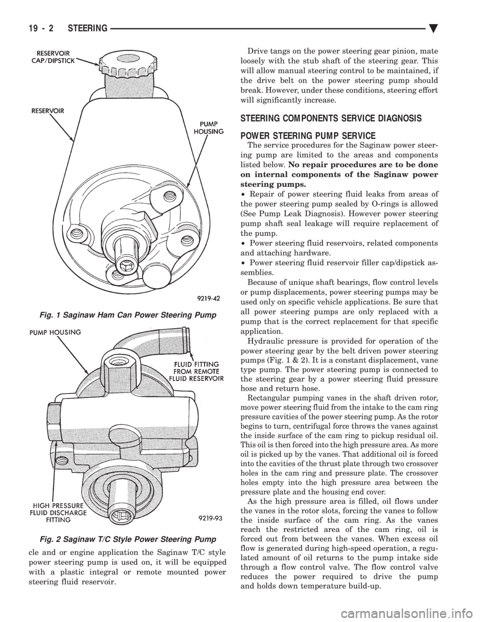
application. Hydraulic pressure is provided for operation of the
power steering gear by the belt driven power steering
pumps (Fig . 1 & 2). It is a constant displacement, vane
type pump. The power steering pump is connected to
the steering gear by a power steering fluid pressure
hose and return hose.
Rectangular pumping vanes in the shaft driven rotor,
move power steering fluid from the intake to the cam ring
pressure cavities of the power steering pump. As the rotor
begins to turn, centrifugal force throws the vanes against
the inside surface of the cam ring to pickup residual oil.
This oil is then forced into the high pressure area. As more
oil is picked up by the vanes. That additional oil is forced
into the cavities of the thrust plate through two crossover
holes in the cam ring and pressure plate. The crossover
holes empty into the high pressure area between the
pressure plate and the housing end cover.
As the high pressure area is filled, oil flows under
the vanes in the rotor slots, forcing the vanes to follow
the inside surface of the cam ring. As the vanes
reach the restricted area of the cam ring, oil is
forced out from between the vanes. When excess oil
flow is generated during high-speed operation, a regu-
lated amount of oil returns to the pump intake side
through a flow control valve. The flow control valve
reduces the power required to drive the pump
and holds down temperature build-up.
Fig. 1 Saginaw Ham Can Power Steering Pump
Fig. 2 Saginaw T/C Style Power Steering Pump
19 - 2 STEERING Ä