1993 CHEVROLET DYNASTY oil
[x] Cancel search: oilPage 526 of 2438

ELECTRONIC CLUSTER
SELF DIAGNOSTIC SYSTEM
The electronic clusters have an internal diagnostics
routing to isolate problems within the cluster or CCD
Bus. Using the cluster Self-Diagnostic Test will deter-
mine whether the problem is within the cluster or
outside of cluster (Fig. 29 and 30). Successful completion of the Self Diagnostic Test
indicates that the problem is in the CCD Bus, inter-
facing modules, connectors, or sensors outside of the
cluster. Refer to Fig. 31 for terminal listing.
CONDITION: CLUSTER DISPLAYS DO NOT ILLUMINATE AFTER VEHICLE IS STARTED
PROCEDURE
(1) Check fuses and verify battery and ignition
voltage at cluster connector. (2) Check ground from cluster connector to instru-
ment panel ground stud.
CONDITION: CLUSTER ASTERISK (*) FLASHES, CLUSTER DISPLAYS NOTINDICATING CORRECT DATA.
PROCEDURE
CCD bus problem. Use the Body Chassis Diagnos-
tic Manual to diagnose CCD Bus.
CONDITION: SPEEDOMETER AND ODOMETER ARE INOPERATIVE OR OPERATESINTERMITTENTLY
PROCEDURE
(1) If speedometer reads 0, or odometer is blank,
and cluster asterisk is flashing, use the Body Chassis
Diagnostic Manual to diagnose CCD Bus problem. (2) If cluster asterisk is not flashing, check for de-
fective vehicle speed sensor or speed sensor wiring.
CONDITION: OIL GAUGE, FUEL GAUGE, TEMPERATURE GAUGE, OR VOLTAGE GAUGEINOPERATIVE
PROCEDURE
If any gauge gives no indication and cluster aster-
isk is flashing, use the Body Chassis Manual to diag-
nose CCD Bus problem. If cluster asterisk is not flashing:
(1) Check for defective sending unit or wiring. (a) Sending units and wiring can be checked by
grounding the connector leads, at the sending unit,
in the vehicle. (b) With the ignition in the ON position, a
grounded input will cause the oil, fuel, or temper-
ature gauge to read maximum. (2) If the problem is with the oil, temperature, or
fuel gauge, check the body controller. If the problem
is with the voltage gauge, check the powertrain con-
trol module operation.
CONDITION: CLUSTER DISPLAY DOES NOT DIM WHEN HEADLAMP SWITCH ISACTIVATED AND RHEOSTAT ROTATED
PROCEDURE
If the cluster asterisk is flashing, Refer to the Body
Chassis Diagnostic Manual to diagnose the CCD Bus. If the cluster asterisk is not flashing:
(1) Check fuses in headlamp circuit.
(2) Check for loose connections or defective wiring
for headlamp switch to body controller. (3) Check for defective headlamp switch. The elec-
tronic instrument cluster receives the display inten-
sity status from the body controller via the CCD Bus.
CONDITION: SEAT BELT WARNING LAMP DOES NOT ILLUMINATE
PROCEDURE
Turn on ignition. Lamp should illuminate for six
seconds. If not: (1) Check for burned out lamp and retest.
(2) Replace cluster.
CONDITION: LOW WASHER, DOOR/DECK, OR MALFUNCTION INDICATOR (CHECK ENGINE)LAMP, DO NOT ILLUMINATE
PROCEDURE
(1) Perform cluster self-diagnostics to determine if
lamp will illuminate. If lamp does not, check for
burned out lamp, replace and retest. (2) If cluster asterisk is flashing, Refer to the Body
Chassis Diagnostic Manual to diagnose CCD Bus. (3) If cluster asterisk is not flashing:(a) For low washer fluid or door/deck, check in-
puts to body controller. (b) For malfunction indicator (check engine),
check powertrain control module operation.
CONDITION: ODOMETER DISPLAY IS BLANK. THE ODOMETER VALUE IS NO LONGERRETAINED IN THIS ELECTRONIC CLUSTER.THIS TAKES PLACE IN THE BODYCONTROLLER
PROCEDURE
(1) If cluster asterisk is flashing, Refer to the Body
Chassis Diagnostic Manual to diagnose CCD Bus. (2) If cluster asterisk is not flashing, perform clus-
ter self-diagnostics. If code 921 appears in the odom-
eter display, replace body controller for odometer
failure.
8E - 34 INSTRUMENT PANEL AND GAUGES Ä
Page 534 of 2438

AG AND AJ BODIES INDEX
page page
Cigar Lighter Removal ..................... 55
Cluster and Gauge Service and Testing ....... 43
Electronic Cluster ........................ 50
Electronic Vehicle Information Center (EVIC) .... 42
Engine Compartment Node ................. 55
Gauges ................................ 44 General Information
....................... 42
Instrument Panel Roll Down Procedure ........ 56
Interior Lamp Removal .................... 57
Mechanical/Electronic Cluster Removal ........ 43
Switch and Panel Component Service ......... 51
Switch Pod Assembly Removal .............. 43
GENERAL INFORMATION
CONVENTIONAL INSTRUMENT CLUSTER
The conventional instrument cluster incorporates
magnetic type gauges (Fig. 1).
The readings are only accurate when the ignition
switch is in the ON position.
TACHOMETER DRIVE MODULE
The tachometer drive module is an electronic mod-
ule used to drive a magnetic tachometer in a conven-
tional instrument cluster.
MESSAGE CENTER
The message center provides the driver with infor-
mation in addition to the standard vehicle instru-
mentation. A bezel will light up with door ajar,
washer fluid, deck ajar and alarm set information.
For vehicles without message center a plain bezel is
used.
ELECTRONIC VEHICLE INFORMATION CENTER
(EVIC)
The Electronic Vehicle Information Center is a
computer controlled warning system which, monitors
various sensors used on the vehicle. The system sup-
plements the warning indicators in the instrument
cluster. Visual warning messages are displayed by a
digital display (Fig. 2). Refer to Group 8C, Overhead
Console.
ELECTRONIC INSTRUMENT CLUSTER
The electronic instrument cluster uses vacuum flu-
orescent displays to display:
² Oil pressure
² System voltage
² Engine temperature
² Fuel level
² Speedometer and tachometer readings as well as
all warning indicators. The electronic cluster is eas-
ily distinguished from the conventional cluster by its
digital and linear display (Fig. 3.
ELECTRONIC CLUSTER DIMMING
The electronic cluster display is dimmed from day-
time to nighttime intensity when the head]lamp
switch is turned on. This intensity can be controlled
using the headlamp switch sliding rheostat. An additional detent on the headlamp switch rheo-
stat will allow daytime intensity while driving with
headlamps ON in daytime.
Fig. 1 Conventional Instrument Cluster
Fig. 2 EVIC
Fig. 3 Electronic Instrument Cluster
8E - 42 INSTRUMENT PANEL AND GAUGES Ä
Page 535 of 2438

ELECTRONIC DIGITAL CLOCK
The electronic digital clock is in the radio. The
clock and radio each use the display panel built into
the radio. A digital readout indicates the time in
hours and minutes whenever the ignition switch is in
the ON or ACC position. When the ignition switch is in the ON or OFF po-
sition, or when the radio frequency is being dis-
played, time keeping is accurately maintained. The procedure for setting the clock varies slightly
with each radio. The correct procedure is described
under the individual radio operating instructions re-
ferred to in the Owner's manual supplied with the
vehicle.
WARNING LAMPS
The AG & AJ Body instrument clusters have warn-
ing lamps or indicators with the electronic cluster for
six different systems. These include low oil pressure,
check gauges, brake system, air bag, seat belt, mal-
function indicator (check engine) lamp.
CLUSTER AND GAUGE SERVICE AND TESTING
CAUTION: Disconnect negative battery cable, in en-
gine compartment, before servicing instrument
panel. When power is required for test purposes,
reconnect battery cable for test only. Disconnect negative battery cable after test and be-
fore continuing service procedures. It is not necessary to remove instrument cluster
from vehicle for gauge replacement. Gauges must be pulled straight out, when remov-
ing or pins may be damaged.
SWITCH POD ASSEMBLY REMOVAL
(1) Disconnect negative battery cable.
(2) Pry up edge of panel vent grille, using a
straight flat edge tool to disengage clips, then re-
move grille (Fig. 4). (3) Remove two screws located under panel vent
grille. (4) Remove two screws underneath switch POD as-
sembly. (5) With tilt steering adjust steering wheel to the
lowest setting. (6) Pull switch module rearward to remove module
and disconnect all wire connections. (7) For Installation reverse above procedures.
Tighten all screws to 2 N Im (20 in. lbs.) torque.
MECHANICAL/ELECTRONIC CLUSTER REMOVAL
CLUSTER MASK AND LENS REMOVAL
(1) Remove switch pod assembly (Fig. 4).
(2) Remove tilt column lever if equipped.
(3) Remove steering column trim cover.
Fig. 4 Switch POD Assembly
Ä INSTRUMENT PANEL AND GAUGES 8E - 43
Page 537 of 2438

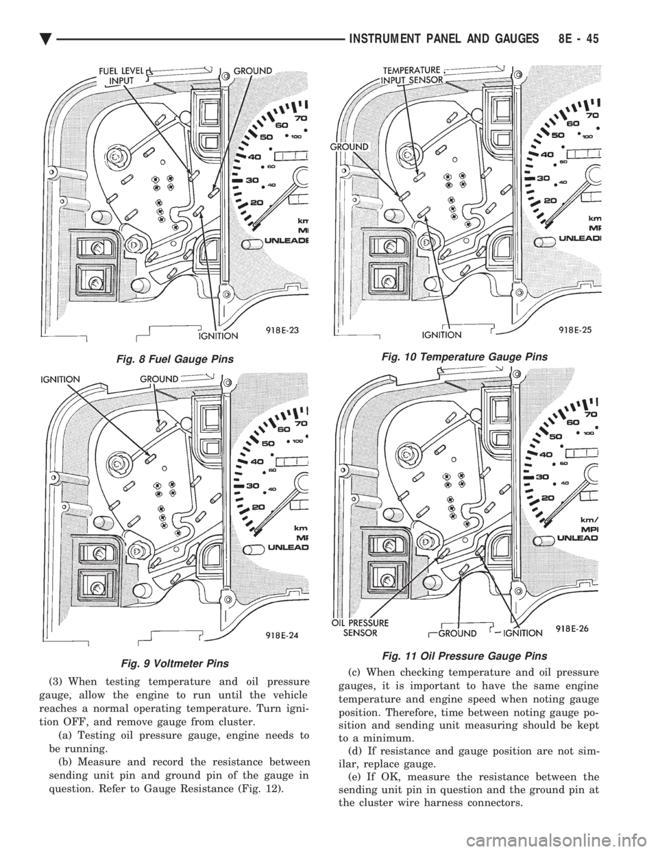
(3) When testing temperature and oil pressure
gauge, allow the engine to run until the vehicle
reaches a normal operating temperature. Turn igni-
tion OFF, and remove gauge from cluster. (a) Testing oil pressure gauge, engine needs to
be running. (b) Measure and record the resistance between
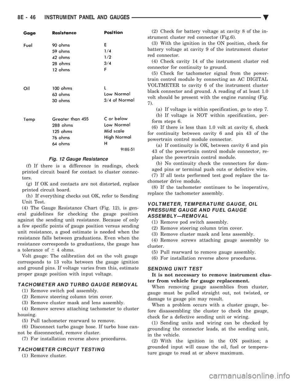
sending unit pin and ground pin of the gauge in
question. Refer to Gauge Resistance (Fig. 12). (c) When checking temperature and oil pressure
gauges, it is important to have the same engine
temperature and engine speed when noting gauge
position. Therefore, time between noting gauge po-
sition and sending unit measuring should be kept
to a minimum. (d) If resistance and gauge position are not sim-
ilar, replace gauge. (e) If OK, measure the resistance between the
sending unit pin in question and the ground pin at
the cluster wire harness connectors.
Fig. 8 Fuel Gauge Pins
Fig. 9 Voltmeter Pins
Fig. 10 Temperature Gauge Pins
Fig. 11 Oil Pressure Gauge Pins
Ä INSTRUMENT PANEL AND GAUGES 8E - 45
Page 538 of 2438

(f) If there is a difference in readings, check
printed circuit board for contact to cluster connec-
tors. (g) If OK and contacts are not distorted, replace
printed circuit board. (h) If everything checks out OK, refer to Sending
Unit Test.
(4) The Gauge Resistance Chart (Fig. 12), is gen-
eral guidelines for checking the gauge position
against the sending unit resistance. Because of only
a few specific points of gauge position versus sending
unit resistance, a good estimate is needed when the
resistance falls between graduations. Even when the
resistance corresponds to graduations, the gauge has
a tolerance of 64 ohms.
Volt gauge: The calibration dot on the volt gauge
corresponds to 13 volts between the gauge ignition
and ground pins. If voltage varies from this, estimate
proper gauge position with input voltage.
TACHOMETER AND TURBO GAUGE REMOVAL
(1) Remove switch pod assembly.
(2) Remove steering column trim cover.
(3) Remove cluster mask and lens assembly.
(4) Remove screws attaching tachometer to cluster
housing. (5) Pull tachometer rearward to remove.
(6) Disconnect turbo gauge hose. If turbo hose can-
not be disconnected, remove cluster. (7) For installation reverse above procedures.
TACHOMETER CIRCUIT TESTING
(1) Remove cluster. (2) Check for battery voltage at cavity 8 of the in-
strument cluster red connector (Fig.6). (3) With the ignition in the ON position, check for
battery voltage at cavity 9 of the instrument cluster
red connector. (4) Check cavity 14 of the instrument cluster red
connector for continuity to ground. (5) Check for tachometer signal from the power-
train control module by connecting an AC DIGITAL
VOLTMETER to cavity 6 of the instrument cluster
black connector and ground. A reading of at least 1.0
volt should be present with the engine running (Fig.
7). (a) If voltage is within specification, go to step 7.
(b) If voltage is NOT within specification, per-
form steps 6.
(6) If there is less than 1.0 volt at cavity 6, check
for continuity between cavity 6 and pin 43 of the
powertrain control module connector. (a) If continuity is OK, between cavity 6 and pin
43 of the powertrain control module connector, re-
place the powertrain control module. (b) No continuity check the connectors for dam-
aged pins or terminal push outs or defective wire.
(7) If all tests performed test good replace the ta-
chometer drive module. (8) If the tachometer continues to be inoperative,
replace the tachometer assembly.
VOLTMETER, TEMPERATURE GAUGE, OIL PRESSURE GAUGE AND FUEL GAUGEASSEMBLYÐREMOVAL
(1) Remove pod switch assembly.
(2) Remove steering column trim cover.
(3) Remove cluster mask and lens assembly.
(4) Remove screws attaching gauge assembly to
cluster. (5) Pull rearward to remove gauge assembly.
(6) For installation reverse above procedures.
SENDING UNIT TEST
It is not necessary to remove instrument clus-
ter from vehicle for gauge replacement. When removing gauge assemblies from cluster,
gauge must be pulled straight out, not twisted, or
damage to gauge pin may result. When a problem occurs with a cluster gauge, be-
fore disassembling the cluster to check the gauge,
check for a defective sending unit or wiring. (1) Sending units and wiring can be checked by
grounding the connector leads, at the sending unit,
in the vehicle. (2) With the ignition in the ON position; a
grounded input will cause the oil, fuel or tempera-
ture gauge to read at or above maximum.
Fig. 12 Gauge Resistance
8E - 46 INSTRUMENT PANEL AND GAUGES Ä
Page 539 of 2438

(3) With the ignition switch ON, an open (discon-
nected sending unit wire) causes the oil, fuel or tem-
perature gauge to read below low, empty or cold
indicators. (4) If steps 2 and 3 check OK, refer to the individ-
ual sending unit test procedures.
FUEL TANK SENDING UNIT TEST
Refer to Group 14, Fuel for test procedure.
CHECK GAUGES WARNING LAMP TESTS
The check gauges warning lamp will illuminated
when the ignition key is turned to the ON position.
The lamp will illuminate if the engine oil pressure
drops below a safe level. The check gauge lamp will
light for high engine temperature or for low voltage. To test the system turn ignition key to the ON po-
sition. If the lamp fails to light, inspect for a broken
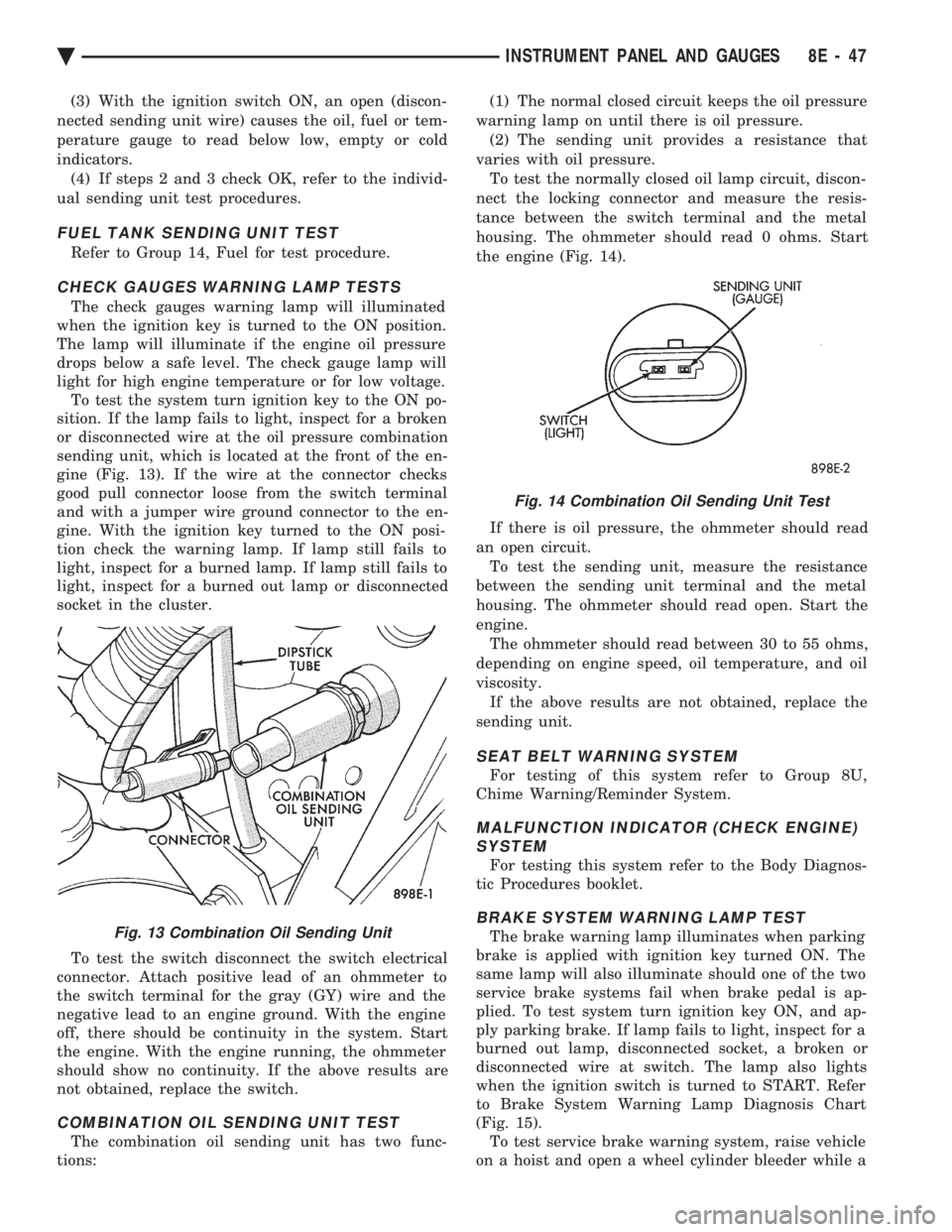
or disconnected wire at the oil pressure combination
sending unit, which is located at the front of the en-
gine (Fig. 13). If the wire at the connector checks
good pull connector loose from the switch terminal
and with a jumper wire ground connector to the en-
gine. With the ignition key turned to the ON posi-
tion check the warning lamp. If lamp still fails to
light, inspect for a burned lamp. If lamp still fails to
light, inspect for a burned out lamp or disconnected
socket in the cluster.
To test the switch disconnect the switch electrical
connector. Attach positive lead of an ohmmeter to
the switch terminal for the gray (GY) wire and the
negative lead to an engine ground. With the engine
off, there should be continuity in the system. Start
the engine. With the engine running, the ohmmeter
should show no continuity. If the above results are
not obtained, replace the switch.
COMBINATION OIL SENDING UNIT TEST
The combination oil sending unit has two func-
tions: (1) The normal closed circuit keeps the oil pressure
warning lamp on until there is oil pressure. (2) The sending unit provides a resistance that
varies with oil pressure. To test the normally closed oil lamp circuit, discon-
nect the locking connector and measure the resis-
tance between the switch terminal and the metal
housing. The ohmmeter should read 0 ohms. Start
the engine (Fig. 14).
If there is oil pressure, the ohmmeter should read
an open circuit. To test the sending unit, measure the resistance
between the sending unit terminal and the metal
housing. The ohmmeter should read open. Start the
engine. The ohmmeter should read between 30 to 55 ohms,
depending on engine speed, oil temperature, and oil
viscosity. If the above results are not obtained, replace the
sending unit.
SEAT BELT WARNING SYSTEM
For testing of this system refer to Group 8U,
Chime Warning/Reminder System.
MALFUNCTION INDICATOR (CHECK ENGINE) SYSTEM
For testing this system refer to the Body Diagnos-
tic Procedures booklet.
BRAKE SYSTEM WARNING LAMP TEST
The brake warning lamp illuminates when parking
brake is applied with ignition key turned ON. The
same lamp will also illuminate should one of the two
service brake systems fail when brake pedal is ap-
plied. To test system turn ignition key ON, and ap-
ply parking brake. If lamp fails to light, inspect for a
burned out lamp, disconnected socket, a broken or
disconnected wire at switch. The lamp also lights
when the ignition switch is turned to START. Refer
to Brake System Warning Lamp Diagnosis Chart
(Fig. 15). To test service brake warning system, raise vehicle
on a hoist and open a wheel cylinder bleeder while aFig. 13 Combination Oil Sending Unit
Fig. 14 Combination Oil Sending Unit Test
Ä INSTRUMENT PANEL AND GAUGES 8E - 47
Page 541 of 2438

SPEEDOMETER/ODOMETER ASSEMBLY REMOVAL
(1) Remove switch pod assembly.
(2) Remove cluster, refer to Cluster Removal.
(3) Remove mask and lens assembly.
(4) Remove tachometer, turbo gauge.
(5) Remove volt, temperature, oil and fuel gauge
assemblies. (6) Remove the speedometer/odometer assembly
from the cluster housing. (7) Disconnect pigtail connector from the cluster
printed circuit board. (8) For installation reverse above procedures. Lis-
ten for the pigtail connector to snap in place.
SPEEDOMETER CIRCUIT TESTING
(1) Using DRB II, check vehicle speed sensor for
speed sensor fault code and for proper speed indica-
tion. Refer to Powertrain Diagnostics Procedure
Manual; Speed Control Test (Fig. 18). (2) Remove cluster, but do not disconnect cluster
wiring. (3) With ignition ON check for battery voltage
across the ignition pin and ground pin of speedome-
ter connector. (4) Check for continuity from vehicle speed sensor
signal pin to connector at speed sensor. (5) Check cluster to body for continuity to ground.
(6) If all these tests prove good, replace speedome-
ter.
VEHICLE SPEED SENSOR REPLACEMENT
(1) Remove harness connector from sensor and
make sure weather seal is on harness connector. (2) Remove sensor retaining bolt (Fig. 19).
(3) Pull sensor and pinion gear assembly out of
transaxle. If necessary carefully pry loose with a flat
blade screwdriver (Fig. 20). (4) Remove pinion gear from sensor.
(5) For installation reverse above procedures. Seat
the sensor assembly by hand to ensure proper gear
engagement. Tighten retaining bolt to 7 N Im (60 in.
lbs.) torque.
ELECTRONIC AUTOMATIC TRANSAXLE VEHICLE SPEED SENSOR REPLACEMENT
The output vehicle speed sensor is located to the
left of the manual shift lever. (1) Raise and support vehicle on safety stands.
(2) Remove vehicle speed sensor (Fig. 21).
(3) For installation, reverse above procedures.
Fig. 17 Speedometer Diagnosis
Fig. 18 Speedometer
Ä INSTRUMENT PANEL AND GAUGES 8E - 49
Page 547 of 2438

AUTOMATIC TEMPERATURE CONTROL LAMP REMOVAL
(1) Remove automatic temperature control from in-
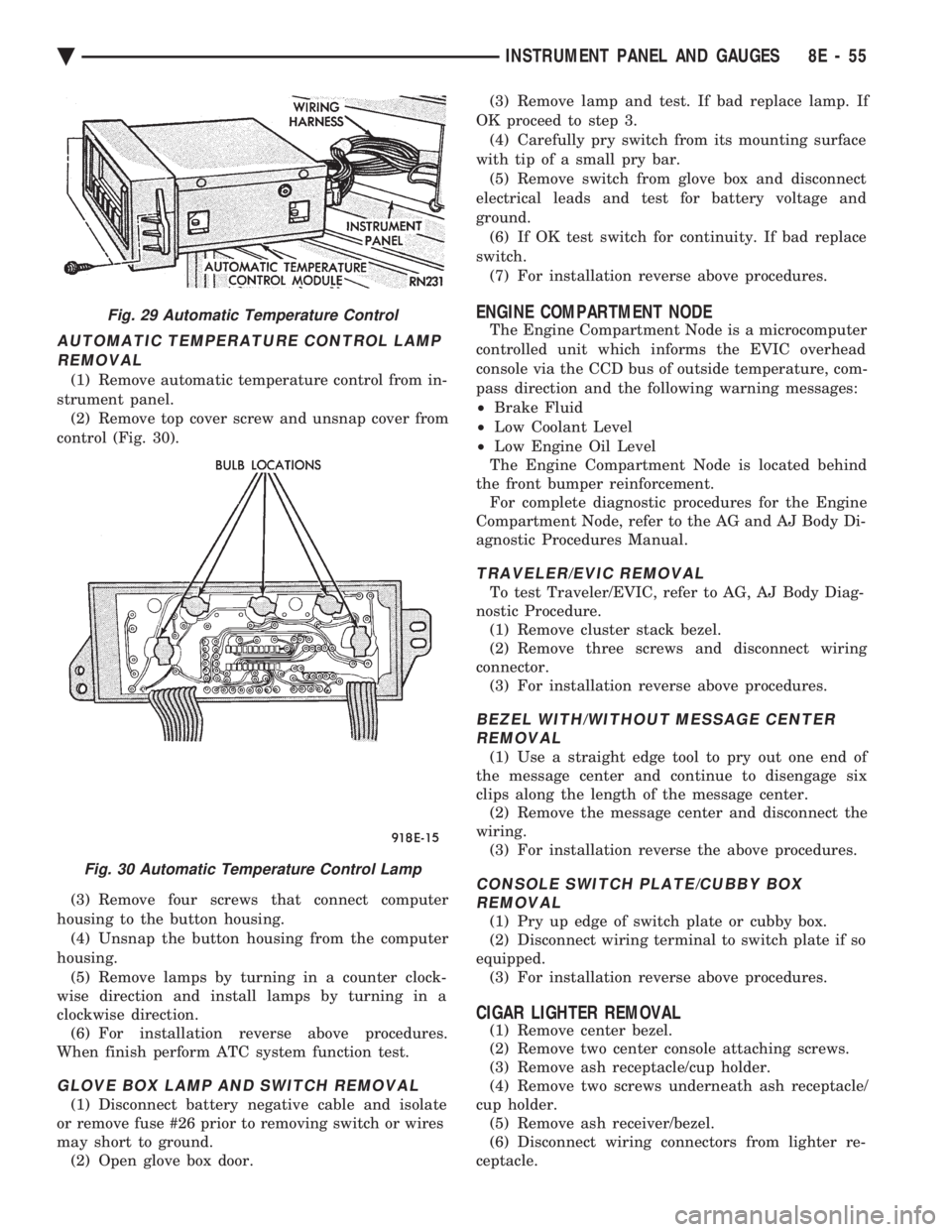
strument panel. (2) Remove top cover screw and unsnap cover from
control (Fig. 30).
(3) Remove four screws that connect computer
housing to the button housing. (4) Unsnap the button housing from the computer
housing. (5) Remove lamps by turning in a counter clock-
wise direction and install lamps by turning in a
clockwise direction. (6) For installation reverse above procedures.
When finish perform ATC system function test.
GLOVE BOX LAMP AND SWITCH REMOVAL
(1) Disconnect battery negative cable and isolate
or remove fuse #26 prior to removing switch or wires
may short to ground. (2) Open glove box door. (3) Remove lamp and test. If bad replace lamp. If
OK proceed to step 3. (4) Carefully pry switch from its mounting surface
with tip of a small pry bar. (5) Remove switch from glove box and disconnect
electrical leads and test for battery voltage and
ground. (6) If OK test switch for continuity. If bad replace
switch. (7) For installation reverse above procedures.
ENGINE COMPARTMENT NODE
The Engine Compartment Node is a microcomputer
controlled unit which informs the EVIC overhead
console via the CCD bus of outside temperature, com-
pass direction and the following warning messages:
² Brake Fluid
² Low Coolant Level
² Low Engine Oil Level
The Engine Compartment Node is located behind
the front bumper reinforcement. For complete diagnostic procedures for the Engine
Compartment Node, refer to the AG and AJ Body Di-
agnostic Procedures Manual.
TRAVELER/EVIC REMOVAL
To test Traveler/EVIC, refer to AG, AJ Body Diag-
nostic Procedure. (1) Remove cluster stack bezel.
(2) Remove three screws and disconnect wiring
connector. (3) For installation reverse above procedures.
BEZEL WITH/WITHOUT MESSAGE CENTERREMOVAL
(1) Use a straight edge tool to pry out one end of
the message center and continue to disengage six
clips along the length of the message center. (2) Remove the message center and disconnect the
wiring. (3) For installation reverse the above procedures.
CONSOLE SWITCH PLATE/CUBBY BOXREMOVAL
(1) Pry up edge of switch plate or cubby box.
(2) Disconnect wiring terminal to switch plate if so
equipped. (3) For installation reverse above procedures.
CIGAR LIGHTER REMOVAL
(1) Remove center bezel.
(2) Remove two center console attaching screws.
(3) Remove ash receptacle/cup holder.
(4) Remove two screws underneath ash receptacle/
cup holder. (5) Remove ash receiver/bezel.
(6) Disconnect wiring connectors from lighter re-
ceptacle.
Fig. 29 Automatic Temperature Control
Fig. 30 Automatic Temperature Control Lamp
Ä INSTRUMENT PANEL AND GAUGES 8E - 55