1992 MAZDA PROTEGE service
[x] Cancel search: servicePage 990 of 1164

ENGINE sro~i32 U
Leak test
1. Carry out the system evacuation and airtightness test as
described above.
2. Prepare as follows according to charging method.
Charging from service container.
Connect the refrigerant service container to the service con-
tainer valve (which is connected to the manifold gauge set air
purge valve) and open the service container.
Charging from freon recovery and recycling system.
Connect the charging valve of the system to the stop valve
(which is connected to the manifold gauge air purge valve).
23UOUX-06
23UOUX-070
I 23UOUX-072
I
80 x 0
23UOUX-07
u-34
3
3. Open the high-pressure side valve of the manifold gauge
set. Charge the system until the low-pressuer side gauge
indicates 98.1 kPa. (1 kg/cm*, 14.22 psi).
4. Close the high pressure side valve.
5. Check for leaks at the system piping joints by using a gas
leak tester.
6. If leaks are found, check the O-rings and tightening torques
at the joints. Replace or retighten as necessary.
7. If no leaks are found, fully charge the system.
Caution
l Carry out the leak test in an well-ventilated but still
air area because it is affected by moving air.
23UOUX-071
Initial charging from service container
1. Carry out the system evacuation, airtightness test, and leak
test.
2. Open the high-pressure side valve of the manifold gauge
set and charge the system as specified.
Charging amount: Approx. 400 g (14.12 oz)
3. Close the high pressure side valve.
4. Start the engine and actuate the A/C compressor.
Caution
l Do not turn the service container upside down while
charging when the engine is running.
l Do not open the high-pressure side valve while the
engine is running.
5. Open the low-pressure side valve of the manifold gauge set
and charge the system to specification.
Specified total refrigerant amount: 800 g (28.24 oz) -.
Page 991 of 1164

U
L
ENGINE STARTED
*-ENGINE STARTED
23UOUX.071
6. Close the low-pressure side valve.
7. Stop the engine.
8. Close the stop valves and the service container valve.
Caution
l Do not disconnect the stop valves or the service
container valve from the charging hoses when there
is refrigerant remaining in the hoses.
Refilling
Caution
l Do not overcharge the system.
l Note the sight glass during refilling the refrigerant.
Stop charging when no bubbles are observed in the
glass.
(Refer to page U-40).
l Care must be taken when the ambient temperature
is low. The bubbles may not be present even if the
refrigerant amount is insufficient.
1. Connect the manifold gauge set to the refrigerant system
charging valve.
(Refer to page U-32).
2. Start the engine.
3. Open the low-pressure side valve of the manifold gauge set
and charge the system as necessary.
4. Note the sight glass, and when no bubbles can be seen,
close the low-pressure side valve.
5. Stop the engine.
6. Close the stop valve and service container valve. Discon-
nect the stop valves quickly.
u-35
Page 1022 of 1164

TECHNICAL DATA
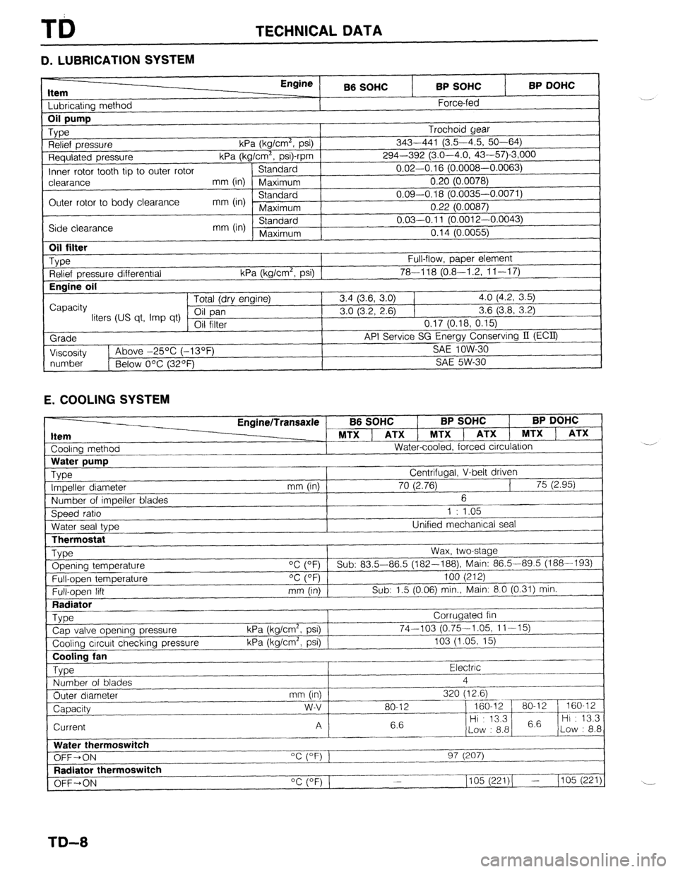
D. LUBRICATION SYSTEM
Item I I bhricatinn mothnd
Engine
B6 SOHC BP SOHC
Force-fed BP DOHC 1
Requlated pressure kPa (kg/Cm”, p
Inner rotor tooth tip to outer rotor Standard
I-‘---- -.----,
clearance mm (in) Maximum 0.20 (0.0078)
Outer rotor to body clearance mm (in) Standard 0.09-0.18 (0.0035-0.0071)
Maximum 0.22 (0.0087)
Side clearance mm (in) Standard 0.03-0.11 (O.pniq n nnn=’
Maximum n4rl ‘-
“” I r-“.““+..I,
I “. I ‘t (U.0055)
I
1
Oil filter
_ Type
Relief pressure differential
Engine oil
I
Capacity
liters (US qt, Imp qt)
Grade
I Viscosity Full-flow, paper element
kPa (kg/cm’, psi) 1 78-l 18 (0.8-I .2, 1 l-l 7) Tntal /An, nnr*inol 3.4 (3.6, 3.0) 1 4.0 (4.2, 3.5)
3.0 (3.2, 2.6) 1 3.6 (3.8, 3.2)
VII 111Lb1 0.17 (0.18, 0.15)
API Service SG Energy Conserving II (ECQ
1
SA!f InW-Xl 1~ Above -25% (-13OF _ .-.. --
I
I
number
1 Below O’C (32OF) SAE 5W-30
1
E. COOLING SYSTEM
Cooling method EnginelTransaxle
MTX ] ATX 1 MTXl
Water-cooled, forced circulation
J B6 SOHC BP SOHC BP DOHC
, ATX 1 MTX ) ATX
LThermostat
Type Opening temperature
Full-open temperature
Full-open lift
Radiator
_ Type
Cap valve opening pressure
Cooling circuit checking pressure Wax, two-stage
“C (OF) Sub: 83.5-86.5 (182--188), Main: 86.5-89.5 (188-193)
OC (OF) 100 (212)
mm (in) Sub: 1.5 (0.06) min., Main: 8.0 (0.31) min.
Corrugated fin
kPa (kg/cm2, psi) 74-103 (0.75-1.05, 11-15)
kPa (kg/cm’, psi) 103 (1.05, 15)
~..
Cooling fan
Type Electric .-
Number of blades 4
_.---- _I___-
Outer diameter mm (in) 320 (12.6)
--_ ~~-
Capacity w-v 80-12 - 160-12 80-l 2 160-12
6.6 Hi : 13.3
6.6 Hi : 13.3
Current A
Low : 8.8 Low : 8.8
_------ ._____
Water thermoswitch
“c (OF) 1
OFF-ON 97 (207)
I--.
Radiator thermoswitch
__-I____-
OFF+ON “C (OF) 1 1105 (221)( - (105 (221)
TD-8
Page 1027 of 1164

TECHNICAL DATA TD
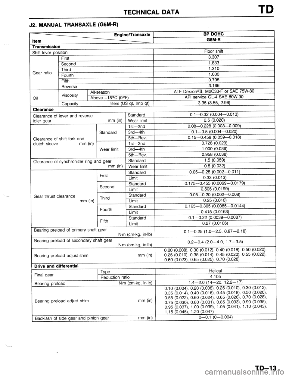
J2. MANUAL TRANSAXLE (G5M-R)
tern EnginelTransaxle BP DoHc
-__-
G BM-R
hansmission
shift lever position
First
Second
Third
;ear ratio
Fnt rrth Floor shift
3.307
1.833
1.310
1.030
3il Reverse
Viscosity
Capacity All-season
Above -18OC (OOF)
liters (US qt, imp qt) a. IOD
ATF Dexron@II, M2C33-F or SAE 75W-80
API service GL-4 SAE 8OW-90
3.35 (3.55, 2.96)
Clearance
Clearance of
idler gear
Clearance of
clutch sleeve
Clearance of lever and reverse Standard 0.1-0.32 (0.004-0.013)
mm (in) Wear limit 0.5 (0.020)
-
1 st-2nd 0.08-0.228 (0.003-0.009)
Standard 3rd-4th 0.1-0.5 (0.004-0.020)
shift fork and 5th~Rev. 0.15-0.458 (0.059-0.018)
mm (in)
1 st-2nd 0.728 (0.029)
Wear limit 3rd-4th 1.000 (0.039)
5th~Rev.
0.958 (0.03
synchronizer ring and gear Standard
mm (in) Wear limit I
First Standard
Limit
I I I 8) 1.5 (0.059)
0.8 (0.032)
0.05-0.28 (0.002’-0.011)
0.33 (0.013)
Gear thrust clearance
mm (in) Second
Third
Fourth
Fifth Standard
Limit
Standard
Limit
Standard
Limit
nr- --,_-..I
3tariuaru
Limit 0.175-0.455 (0.0069-0.0179)
0.505 (0.0199)
0.05-0.20 (0.002-0.008)
0.25 (0.010)
0.165-0.365 (0.0065-0.0144)
0.415 (0.0163)
al-O.22 (0.0039-0.0087)
0.27 (0.0106)
Bearing preload of primary shaf t gear
N.m (cm-kg, in-lb) 0.1-0.25 (1.0-2.5, 0.87-2.18)
Bearing preload of secondary shaft gear
N.m (cm-kg, in-lb)
Bearing preload adjust shim mm (in)
Drive and differential
Type
Final gear
Reduction ratio
Bearing preload N.m (cm-kg, in-lb)
Bearing
preload adjust
shim (in) mm
Backlash of side gear and pinion gear mm (in) 0.2-0.4 (2.0-4.0, 1.7-3.5)
0.20 (0.008) 0.30 (0.012) 0.40 (0.016) 0.50 (0.020)
0.25 (O.OlO), 0.35 (0.014) 0.45 (0.020) 0.55 (0.022)
0.60 (0.023) 0.65 (0.025) 0.70 (0.028)
Helical
4.105
1.4-2.0 (14-20, 12.2---17)
0.10 (0.004) 0.20 (0.008) 0.25 (0.010) 0.30 (0.012)
0.35 (0.014) 0.40 (0.016) 0.45 (0.018) 0.50 (0.020)
0.55
(0.022) 0.60
(0.024) 0.65 (0.026) 0.70 (0.028)
0.75 (0.030) 0.80 (0.031) 0.85 (0.033) 0.90 (0.035)
0.95 (0.037) 1.00 (0.039), 1.05 (0.041) 1.10 (0.043)
1 ,15 (0.045) 1.20
(0.047)
o-o.1 (O-0.004)
TD-13
Page 1038 of 1164

ST SPECIAL TOOLS
GENERAL INFORMATION
The letters A and B in the priority column indicate the degree of importance of each tool.
A.. . Indispensable
The tools ranked A in this list are indispensable for performing operations satisfactorily, easily, safely, and
efficiently. It is, therefore advisable that all service shops have these tools.
B.....Selective
The tools in this list are not as necessary as tools ranked A, but all service shops should have these tools
to perform repairs more easily and more efficiently.
23USTX-002
ST-2
Page 1069 of 1164

Troubleshooting Z-Gl-13
el
-
Ill
31
-
I1
Jl
:n
r.
7a
ver
le
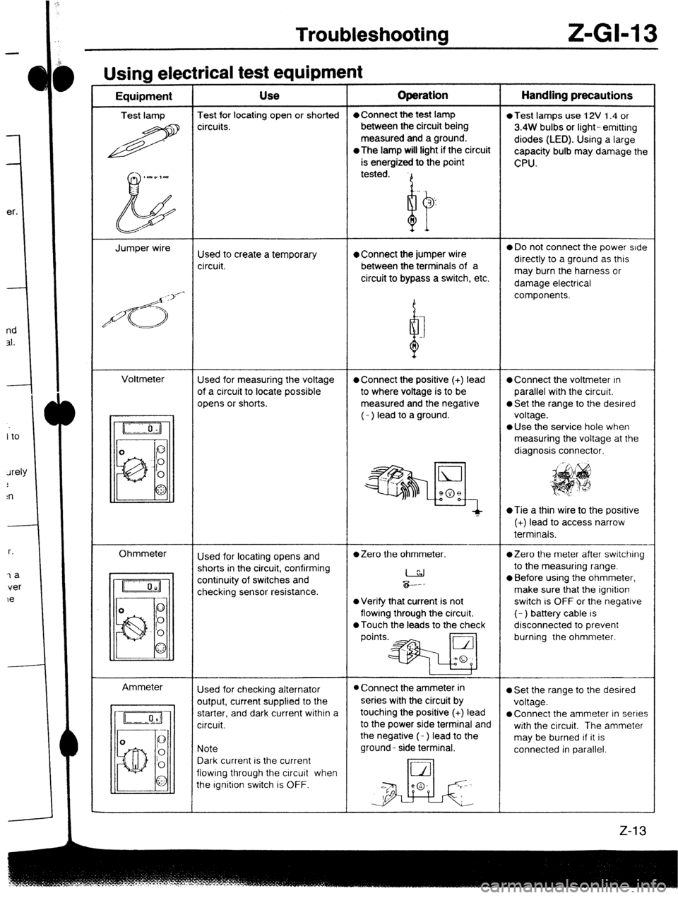
Usina electrical test eaubment -----w - I - Equipment Use Operation Handling precautions
Test lamp Test for locating open or shorted l Connect the test lamp
0 Test lamps use 12V 1.4 or
R circuits. between the circuit being
3.4W bulbs or light- emitting
measured and a ground.
diodes (LED). Using a large
*The
lamp will light if the circuit
capacity bulb may damage the
is energized to the point
CPU.
,.WD,.l
b tested.
Jumper wire
Used to create a temporary l Connect the jumper wire 0 Do not connect the power side
circuit. between the terminals of a directly to a ground as this
circuit to bypass a switch, etc. may burn the harness or
damage electrical
/d<;>‘-
d components.
I
n
Voltmeter
Used for measuring the voltage
l Connect the positive (+) lead l Connect the voltmeter In
of a circuit to locate possible to where voltage is to be parallel with the circuit.
opens or shorts. measured and the negative
0 Set the range to the desired
(- ) lead to a ground. voltage.
l Use the service hole when
measuring the voltage at the
diagnosis connector.
~Tie a thin wire to the posrtive
(+) lead to access narrow
terminals.
Ohmmeter
Ammeter Used for locating opens and
l Zero the ohmmeter. *Zero the meter after switching
shorts in the circuit, confirming
I to the measuring range.
continuity of switches and
checking sensor resistance. &.--
l Before using the ohmmeter,
make sure that the ignition
l Verify that current is not switch is OFF or the negative
flowing through the circuit. (- ) battery cable is
0 Touch the leads to the check disconnected to prevent
points.* burning the ohmmeter.
Used for checking alternator
l Connect the ammeter in l Set the range to the desired
output, current supplied to the series with the circuit by
voltage.
starter, and dark current within a touching the positive (+) lead
l Connect the ammeter in series
circuit. to the power side terminal and
with the circuit. The ammeter
the negative (- ) lead to the
may be burned If it is
Note ground- side terminal.
connected in parallel.
Dark current is the current
flowing through the circuit when
the Ignition switch is OFF.