1992 MAZDA PROTEGE engine coolant
[x] Cancel search: engine coolantPage 434 of 1164

F CONTROL SYSTEM
23UOFX-l! 51
.
r---- - --------1
I
I
i I
I
:,
m7 I
- - -.-
Fc E, Vc Ez 23UOFX-158
WATER THER@OSENSOA
I
03UOFX-21
REPLACE WASHEF
f
OYJOFX-2’
AIRFLOW METER (WITH INTAKE AIR THERMOSENSOR)
Inspection
1. Remove the airflow meter. (Refer to page F-109.)
2. Check the airflow meter body for cracks.
3. Verify that the measuring plate moves smoothly.
4. Move the measuring plate and check for resistance between
the terminals with an ohmmeter.
Specification
Terminal
E2 * Vs
E2 ++ Vc
E2
* THAA
(Intake air thermosensor)
El +, Fc Resistance (0)
Fully closed 1
Fully open
20-600 1 20-l ,000
200-400
-20% ( -4’=F): 13.6- 18.4 KQ
20% ( 6899 2.21-2.69 kD
60°C (14OOF): 493- 6670
00
0
WATER THERMOSENSOR
Removal
Note
l Water thermosensor Is placed at:
Rear of engine . . . . . . . . . . . . . . . . . . . . . . . . ..*.............. BP
Intake manifold ,.*......,..m...,..,.....*....*......... 86 -’
1. Disconnect the water thermosensor connector.
2. Remove the water thermosensor.
Inspection
1. Place the sensor in water with a thermometer and heat the
water gradually.
2. Measure resistance of the sensor with an ohmmeter.
3. If not as specified, replace the water thermosensor.
lnstallatlon
1. Install a new washer and the water thermosensor.
Tlghtening torque:
25-29 N.m (2.5-3.0 m-kg,
18-22 ft-lb)
2. Connect the water thermosensor connector.
3. Start the engine and check for coolant leakage.
F-l 68
Page 710 of 1164

R OUTLINE
OUTLINE
SPECIFICATIONS
Suspension type Item Specification Strut
Shock absorber Double-acting, oil-filled
Coil spring
Stabilizer Type Front Taper wound
Rear Straight wound
Dimension See coil spring specification below
Type Torsion bar
BP SOHC Front 19.1 (0.75) (Hollow type)
Rear 20.0 (0.79) (Hollow type)
Diameter 22.0 (0.87) (Solid type)
mm (in) BP DOHC ;eTrt
21 .O (0.83) (Solid type)
P ,
-
66 SOHC rronr
Rear 20.0 (0.79) (Hollow type)
Maximum Inner 400 f 20
steering angle
Outer 330 f 20
Total mm (in) 2 f 3 (0.08 f 0.12)
Front toe-in
degree 0.2O f 0.3O
Wheel alignment
(*‘Unladen) Camber angle -0005’ f 45’
Caster angle 1055 * 55’
Kingpin angle 12O25’
Total mm (in) 2 f 3 (0.08 * 0.12)
Rear toe-in
degree 0.2O f 0.3O
Camber angle -0°20’ f 45’
*’ Fuel tank full; radiator coolant and engine oil at specified levels; and spare tire, jack, and tools in designated positions.
23UORX.004
Coil Spring Specifications (See next page for coil spring applications)
I Item Wire diameter Coil center Free lel.=-. .
mm iin1 rliamotor mm [in mm (in 1 coil numbs
Front
nath
1 _ . . *St Identification mark color +l
., . . . . I...,
-*.....-.“, * . . . . . ,..-, -....- I--‘, M iA*=
A 13.1 (0.52) 133.5-159.5 (5.26-6.28)
294.5 (11.59) 3.22 Light green
B 13.3 (0.52) 133.7-159.9 (5.26-6.30) 300.5 (11.83)
3.43 Purple Yellow
C 13.4 (0.53)
132.6-158.6 (5.22-6.24) 301.5 (11.87) 3.49
Light blue
D 13.7 (0.54)
132.9-158.9 (5.23-6.26) 302.0 (11.89) 3.52
Pink White
I F I 12f3 Kl5Al I 1.17 A-l!% 8 f!i PR-Fi 751
I RrIl .5 II 1 6x71 I 3.56 Orange
Blue
3 83 Pink -
Brown - .“._ \“.- .,
. “W.., ~ - -. - \-. -- -. - -, -- .-
\’ .‘-‘I t
F 11 .o (0.43) 129.0 (5.08)
335.0 (13.19) -.--
G 11.2 (0.44) 128.8 (5.07)
334.0 (13.15) 3.94
Rnnr l-4
1 I ? 07 AA 1387 /5n7
.?m !i 113 1% 3 an Blue - I I I I .” \v.-7, I&V., \V.“., ---.., \.-. .-, I 11.5 (0.45) 128.5 (5.06)
333.0 (13.11) i:oi Gray
-
J 11.6 (0.46) 128.4 (5.06)
332.5 (13.09) 4.00 Orange
-
l ’ Main identification mark color: Indicated on second coil from bottom.
*’ Auxiliary identification mark color: Indicated on third coil from bottom. 23UORX-005
R-4
Page 713 of 1164

WHEEL ALIGNMENT
WHEEL ALIGNMENT
PRE-INSPECTION
1. Check the tire inflations and set to the recommended pressure, if necessary.
2. Inspect the front wheel bearing play; replace the bearing if necessary.
3. inspect the wheel and tire runout.
4. Inspect the ball joints and steering linkage for any excessive looseness.
5. The vehicle must be on level ground and have no luggage or passenger load.
6. The difference in height between the left and right sides from the center of the wheel to the fender brim
must not exceed
10mm (0.39 in).
7. Shake the vehicle to check operation of the shock absorbers.
03UORX.007
FRONT WHEEL ALIGNMENT
Specifications
item
Specifications
Maximum Inner 4o” f: 2O
steering angle Outer
33O f 2O
Total mm (in) 2 f 3 (0.08 f 0.12)
toe-in dearee 0.20 f 0.30 Wheel alignment
(*‘Unladen) Front
*I Fuel tank full; radiator coolant and Camber angle -0005 * 45’
Caster angle 1°55’ f 55’
Kingpin angle 12O25’
engine oil at specified level; and spare tire, jack, and tools in designated positions.
23UORX-008
I
I 23UORX-023
Adjustments
Maximum steering angle
1. Loosen the left and right tie rod locknuts, then turn the tie
rods equally.
Maximum left/right difference: 3mm (0.12 in)
2. Tighten the tie rod locknuts.
Tightening torque:
34-50 N-m (3.5-5.1 m-kg, 25-37 ft-lb)
3. Adjust the toe-in after adjusting the steering angle.
4. Inspect and adjust the toe-in after adjusting the turning angle.
I 23UORX-024
R-7
Page 715 of 1164

WHEEL ALIGNMENT
REAR WHEEL ALIGNMENT
Specifications
kern Specifications
Total mm (in) 2 f 3 (0.08 f 0.12)
Wheel alignment
(*‘Unladen) Rear toe-in
degree 0.2O f 0.3O
Camber angle -0020’ f 45’
*I Fuel tank full; radiator coolant and engine oil at specified level; and spare tire, jack, and tools in designated positions.
13UORX-012
Adjustment
Total toe-in
1. Loosen the lateral link locknuts.
2. Turn the lateral link adjustment link to adjust.
Note
l One turn of the link changes 11.3mm (0.44 in).
3. Tighten the lateral link locknuts to the specified torque.
Tightening torque:
55-64 N,m (5.6-6.5 m-kg, 41-47 ft-lb)
R-9
Page 977 of 1164

HEATER U
HEATER UNIT
Removal / Installation
1. Drain the engine coolant.
2. Remove the dashboard. (Refer to Section S.)
3. Remove as shown in the figure.
4. Install in the reverse order of removal
Note
l When disconnecting the heater hose from the heater core, unlock the hose connector at the
heater core side.
l When installing the heater hose on the heater core, verify that the hose connector is securely
locked.
l Release the clamp, and remove the seal plate together with the heater unit.
1. Seal plate 3. Heater hose
2. Hose connector
4. Heater unit
u-21
Page 1023 of 1164

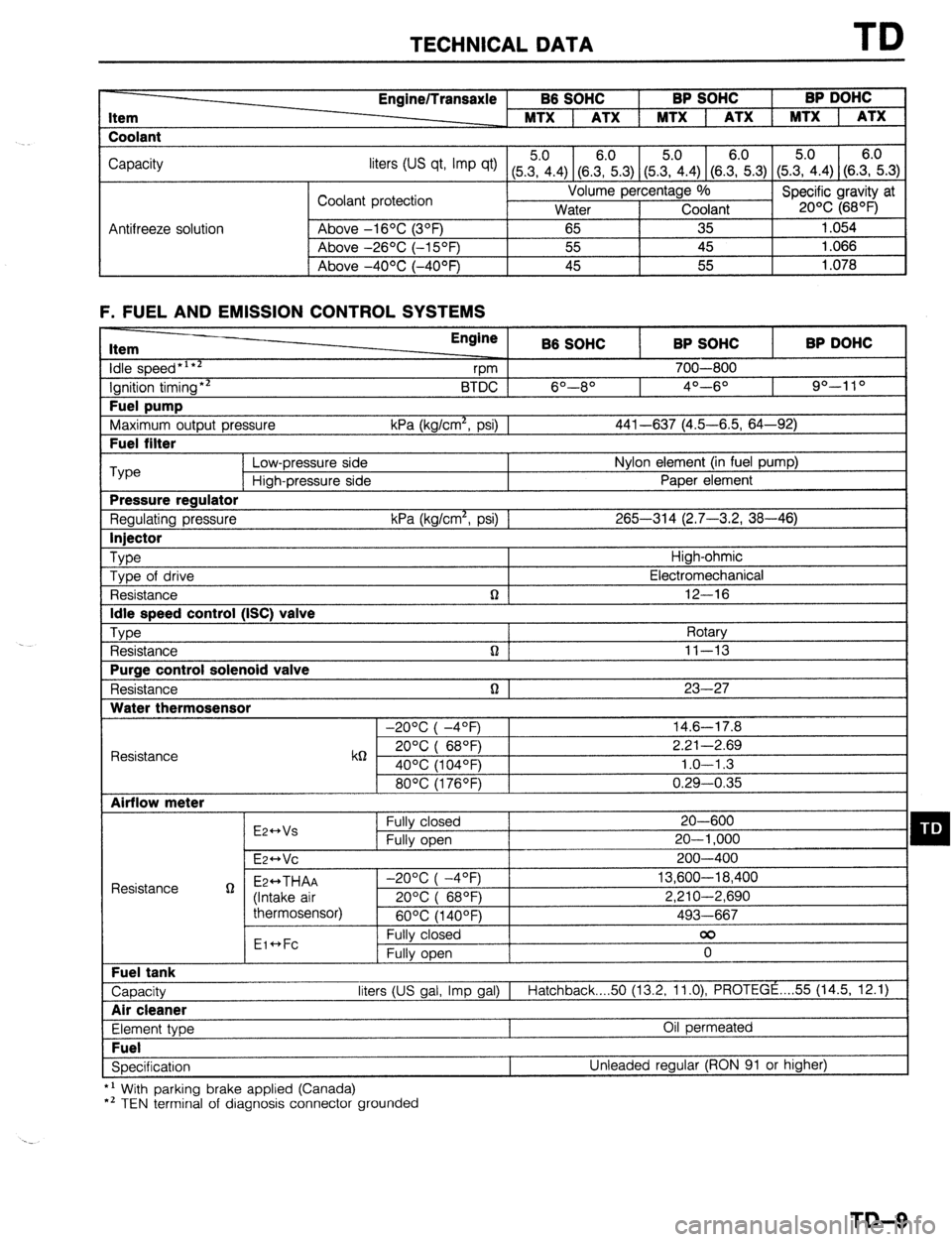
TECHNICAL DATA TD
Item
Coolant Engine/Transaxle B6 SOHC BP SOHC BP DOHC
MTX 1 ATX 1 MTX 1 ATX 1 MTX 1 ATX
Capacity
liters tus qt, Imp qt) (5Z.4) (8.E.3) (5&4) (SE.3) (5.?i.4) (S.E.3)
Coolant protection Volume percentage %
Specific gravity at
Water Coolant 20% (68OF)
Antifreeze solution Above -16OC (3OF)
65 35 1.054
Above -26OC (-15OF) 55 45 1.066
I Above -4OOC (-40°F) 45 55
1.078
F. FUEL AND EMISSION CONTROL SYSTEMS Item
idle speed*‘**
Ignition timing** Fuel pump
Maximum output pressure Fuel filter Engine
B6 SOHC BP SOHC BP DOHC
vm 700-800
BTDC 6O--8O 4O---6O 90-l 10
kPa (kg/cm*, psi) 1 441-637 (4.5-6.5, 64-92) ‘Type
Low-pressure side Nylon element (in fuel pump)
High-pressure side Paper element Pressure regulator
Regulating pressure kPa (kg/cm*, psi) 1 265-314 (2.7-3.2, 38-46) Injector
Type
High-ohmic
Type of drive Electromechanical
Resistance n 12-16 Idle speed control (ISC) valve
Type
Rotary
Resistance n ] 11-13 Purge control solenoid valve
Resistance n 1 23-27 Water thermosensor
-20°C( -4OF) 14.6-17.8
Resistance k6 20°C( 68QF) 2.21-2.69
40% (104OF) 1.0-l .3
80°C(1760F) 0.29-0.35 Airflow meter
E2++Vs Fully closed 20-600 q D Fully open 20-l ,000
E~HVC 200-400
Resistance g Ez++THAA -2O%(-4OF) 13,600-18,400
(Intake air 20%( 68OF) 2,210-2,690
thermosensor)
60°C(1400F) 493-667
Eic*Fc Fully closed 00
Fully open 0 Fuel tank
Capacity liters (US gal, Imp gal) I
Hatchback 50 (13.2, 11.0) PROTEGE . . . . 55 (14.5, 12.1) Air cleaner
Element type Oil permeated Fuel
Specification Unleaded regular (RON 91 or higher)
*’ With parking brake applied (Canada)
*’ TEN terminal of diagnosis connector grounded
TD-9
Page 1033 of 1164

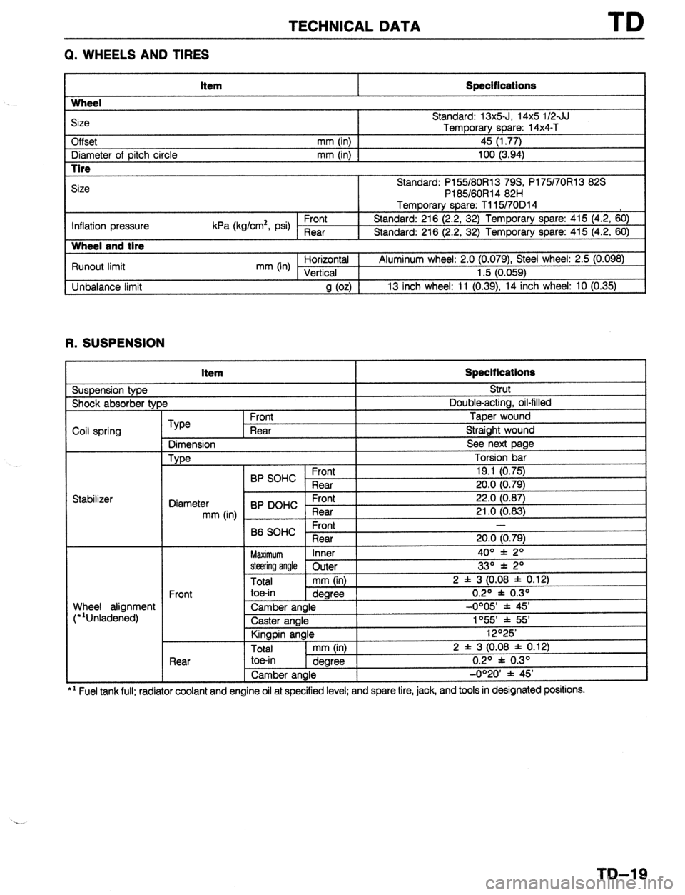
TECHNICAL DATA
Q. WHEELS AND TIRES
Item Specifications
Wheel
Size
Off set Standard: 13x5-J, 14x5 l/2-JJ
Temporary
mm (in) 1 _ spare: 14x4-T
45 (1.77)
I Diameter of oitch circle
mm (in) I 100 (3.94)
r I Pl
-
Inflation pressure kPa (kg/cm*, psi) Front 1 8
I 9
Runout limit
Unbalance limit mm (in) ;lii.raltLa’
a (02) ’
13 inch wheel: 11 (0.
R. SUSPENSION Item Specifications
Suspension type Strut
)e Double-acting, oil-filled
I Shock absorber tyf
Coil spring
Type
Dimension
Type Front Taper wound
Rear Straight wound
See next page
Torsion bar
I
I C.rrn,
19.1 (0.75)
20.0 (0.79)
22.0 (0.87)
21 .O f0.83)
Wheel alignment
(“‘Unladened) BP SOHC ;;a;
Diameter
mm (in) BP DOHC - ;la;t
Front -
B6 SOHC
Rear 20.0 (0.79)
Maximum Inner 4o” f 2O
steering angle Outer
Total mm (in) 2 f 3 (0.08 j
Front toe-in
dearee
.-.._
Rear
.--. I --- ~~
Camber angle
Caster angle
Kingpin angle
I Total
I mm OnI I I toe-in
1 dearee I , --U’-- 1
Camber angle
I 33O * 2O
: 0.12)
0.2O f 0.3O
-0OO5’ * 45’
1055’ * 55’
12O25’
2 f 3 (0.08 f 0.12)
0.2O f 0.3O
-0°20’ f 45’
l ’ Fuel tank full; radiator coolant and engine ail at specified level; and spare tire, jack, and tools in designated posmons.
TD-19
Page 1050 of 1164

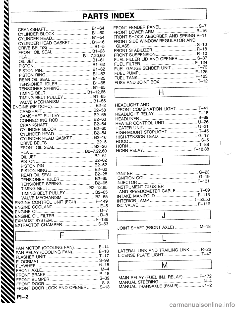
PARTS INDEX
I
CRANKSHAFT.. ....................................
I31 -64
CYLINDER BLOCK .............................. 61-60
CYLINDER HEAD..
............................... 81-54
CYLINDER HEAD GASKET .................
Bl-16
DRIVE BELT(S). ...................................... 81-5
FRONT OIL SEAL ................................ 81-23
HLA .............................................. Bl-7,20,60
OIL JET ................................................ 81-61
PISTON.. ...............................................
Bl-62
PISTON PIN..
........................................ 81-62
PISTON RING
....................................... 81-62
REAR
OIL SEAL..
................................. 81-25
TENSIONER, IDLER ............................. Bl-65
TENSIONER
SPRING ...........................
Bl-65
TIMING BELT ..................................
Bl-12,65
TIMING BELT PULLEY ........................
Bl-65
VALVE MECHANISM ........................... Bl-55
ENGINE
(BP DOHC) .................................... B2-2
CAMSHAFT ..........................................
82-58
CAMSHAFT PULLEY ...........................
B2-65
CONNECTING ROD..
........................... 82-63
CRANKSHAFT ......................................
B2-64
CYLINDER BLOCK ..............................
82-60
CYLINDER
HEAD.. ............................... B2-54
CYLINDER HEAD GASKET .................
82-16
DRIVE
BELTS.. .......................................
B2-5
FRONT
OIL SEAL ................................
82-26
H LA ..............................................
OIL JET .......................... B2-7iyL;;
......................
PISTON .................................................
B2-62
PISTON PIN ..........................................
82-62
PISTON RING..
..................................... 82-62
REAR OIL SEAL ................................... B2-28
TENSIONER, IDLER ............................. B2-65
TENSIONER SPRING ........................... B2-65
TIMING
BELT.. ................................
B2-12,65
TIMING BELT PULLEY ........................ 82-65
VALVE MECHANISM ........................... 82-55
ENGINE CONTROL UNIT (ECU) ............... F-149
ENGINE COOLANT
........................................ E-5
ENGINE OIL.. .................................................
D-7
ENGINE OIL FILTER.. .................................... D-8
’ EXHAUST SYSTEM. ...................................
F-136
EXTRACTOR CHAMBER .............................. S-53
F
FAN MOTOR (COOLING FAN). ................... E-14
FAN RELAY (COOLING FAN). ..................... E-18
FLASHER UNIT ............................................
T-17
FLOORMAT ..................................................
S-99
FLYWHEEL ..................................................
H-18
FRONT AXLE .................................................
M-4
FRONT BRAKE ............................................
P-l 8
FRONT BUMPER ......................................... S-39
FRONT DOOR ................................................
S-8
FRONT DOOR LOCK AND OPENER ..........
S-13
PI-2
FRONT FENDER PANEL ............................... S-7
FRONT LOWER ARM .................................. R-16
FRONT SHOCK ABSORBER AND SPRING R-11
FRONT SIDE WINDOW REGULATOR AND
GLASS ........................................................ S-10
FRONT STABILIZER..
................................... R-l 8
FRONT SUSPENSION .................................. R-l 0
FUEL FILLER LID AND OPENER..
.............. S-37
FUEL FILTER .............................................. F-l 24
FUEL GAUGE SENDER UNIT ..................... T-73
FUEL PUMP ............................................... F-125
FUEL TANK
................................................ F-123
FUSE AND JOINT BOX.. .............................. T-12
H
HEADLIGHT AND
FRONT COMBINATION LIGHT..
................ T-41
HEADLIGHT RELAY ..................................... T-l 8
HEADLINER ................................................. S-89
HEATER CONTROL UNIT.. ......................... U-26
HEATER UNIT
.............................................. U-21
HIGH-MOUNT STOPLIGHT
.......................... T-45
HIGH-TENSION LEAD ................................. G-l 7
HOOD ............................................................. S-5
HORN T-88
...........................................................
HORN RELAY
.......................................... T-18,88
.__. ’
I I
IGNITER .......................................................
G-23
IGNITION COIL.. .......................................... G-19
INJECTOR .................................................. F-l 31
INSTRUMENT CLUSTER
AND SPEEDOMETER CABLE
.................... T-69
INTAKE MANIFOLD ................................... F-113
INTERIOR LAMP ..................................... T-52,53
ISC VALVE.. ................................................ F-l 16
J
JOINT SHAFT (FRONT AXLE) .................... M-18
L
LATERAL LINK AND TRAILING LINK.. ....... R-26
LICENSE PLATE LIGHT.. ............................. T-47
i
M
I
---
MAIN RELAY (FUEL INJ. RELAY). ............ F-172
MANUAL STEERING ..................................... N-4
MANUAL TRANSAXLE (F5M-R). .................. Jl-2