1992 MAZDA PROTEGE parking brake
[x] Cancel search: parking brakePage 699 of 1164

PARKING BRAKE SYSTEM
PARKING BRAKE LEVER
Removal / Inspection / Installation
Caution
l Install the parking brake switch so that it contacts the parking brake lever when the lever is
fully released.
l Turn the ignition switch ON, and check that the parking brake warning lamp illuminates with
the lever pulled one notch.
1. Block the wheels firmly.
2. Release the parking brake.
3. Remove in the order shown in the figure.
4. Inspect all components and parts, Replace parts if necessary.
5. Install in the reverse order of removal.
6. After installation: Adiust the parking lever stroke. (Refer to paae P-31 .)
N.m (m-kg, R-lb)
23UOPX.022
1. Rear console 5. Parking brake switch
Removal / Installation . . . . . . . . . . . . . . . . . . . . . Section
S 6. Parking brake cap
2. Adjusting nut 7. Release button
3. Bolt 8. Parking lever spring
4. Parking brake lever assembly 9. Parking brake lever
Inspect for damage and wear
P-33
Page 889 of 1164

EXTERIOR LIGHTING SYSTEM T
Headlights either do not operate or are dim Low-High beam or passing flasher does not
J operate
Burnt out bulb or poor grounding J
03UOTX-049 Defective combination switch
03UOTX-050
(Canada) Daytime running lights (DRL) do not operate
Confirm that headlights operate with the light switch ON
(second position) OK
Turn OFF the light switch and turn ON the ignition
switch when parking level pulling
I
Check head 30A main fuse OK
Check DRL resistor OK Repair DRL resistor 10A fuse
Confirm battery voltage on R and L/G wire of the DRL NG
relay Repair harness (Fuse - DRL relay)
I
I
Check the DRL relay
Repair DRL relay
1 OK
Confirm battery voltage on (BRNV) wire of the DRL con-
trol unit NG
Repair harness (DRL relay - DRL control unit) OK
Confirm battery voltage on (L/G) wire of the DRL control NG
unit Repair harness (Rear wiper fuse - DRL control unit) OK
Confirm continuity of (G/R) wire of the DRL control unit x Repair harness (DRL control unit - Parking brake
to ground switch) or check the parking brake switch 1 OK
Confirm continuity on (B) wire of the DRL control unit to
NG
ground Repair harness (DRL control unit ground) OK
-1 NG
Confirm approx. 8V on the DRL resistor Repair harness (DRL control unit - DRL headlight)
I
Confirm battery voltage on (
Confirm approx. 8V on (R/W) wire of the DRL resistor Repair harness (DRL resistor - DRL relay)
Repair harness (DRL control unit - DRL resistor)
23UOTX-019
T-33
Page 917 of 1164

WARNING SYSTEM T
13UOTX-07
63U15X-05
, I//
‘nF -
-
-
FUEL
13UOTX.08C
- CHARGE
13UOTX-08
13UOTX-08
Inspection
Brake system warning lamp
1. Disconnect the connector from the brake fluid level sensor.
2. Connect a jumper wire between “G/Y” and “6” terminal
(body ground).
3. Start the engine and check that the BRAKE warning lamp
illuminates.
Caution
l Be sure that the parking brake is fully released be-
fore checking.
4. If there is no illumination, check the fuse, bulb, and wiring
harness.
Brake fluid level sensor
Connect an ohmmeter to each terminal of the brake fluid lev-
el sensor connector.
Check for continuity when the float is moved up and down.
The sensor is good if there is continuity when the float is be-
low the “MIN” mark, and if there is no continuity when the
float is above the “MAX” mark. If the sensor does not pass
this test, replace it.
Fuel-level warning lamp
1. Disconnect the connector from the fuel tank unit.
2. Connect the connector terminal “W/R” to the body ground.
3. Start the engine and check that the FUEL warning lamp il-
luminates.
4. If there is no illumination, check the fuse, warning lamp, and
wiring harness.
Alternator warning lamp
1. Start the engine, connect the connector terminal “W/B” to
a body ground.
2. Check that the alternator warning lamp illuminates.
3. If there is no illumination, check the warning lamps, wiring
harness and alternator. Replace or repair as necessary.
Engine oil pressure warning lamp
1. Disconnect the connector from the oil pressure switch.
2. Start the engine and connect the connector terminal “Y/R”
to a body ground.
3. Check that the “OIL” warning lamp illuminates. If it does
not, replace the sender switch or repair the wiring harness
if bulb is not burnt out.
T-61
Page 920 of 1164

2L BUZZER 2A 28 2C 2D 1A 3K l--r nnmn
I I‘ I
1C 3L 2E 2G IL iG 1F 1D tB
3F 38 3G 1E 3D
l-l rt
II l-l
l-l It II l-l 1J 11 1H
1G IF 1E 1D 1C 1B 1A 2L 2K 2J 21 2H 2G 2F 2E 2D 2C 28 2A
r-l It ,I 3L 3K 3J 31 3H 3G 3F 3E 3D 3C 3B 3A
Ter- I I minal Connected to 1 1A Combination switch
1B Ground
IC Fuel tank unit
1 ID 1 EGI control unit
I
II L 1J 1
L Ter-
minal Connected to
2A Speed sensor output
28 Light switch (high beam)
2C Turn switch (L)
20 Turn switch (R)
2E Ground
2F Ground
2L 1 IGI battery Ter-
minal Connected to
3A
38 Alternator
3c
30 Oil pressure switch
3E
3F Parking brake switch, Brake fluid switch
3G Passive shoulder belt control unit
3H h
I 31
3J
3K
IG2 battery
3L Water temperature gauge unit
Page 1023 of 1164

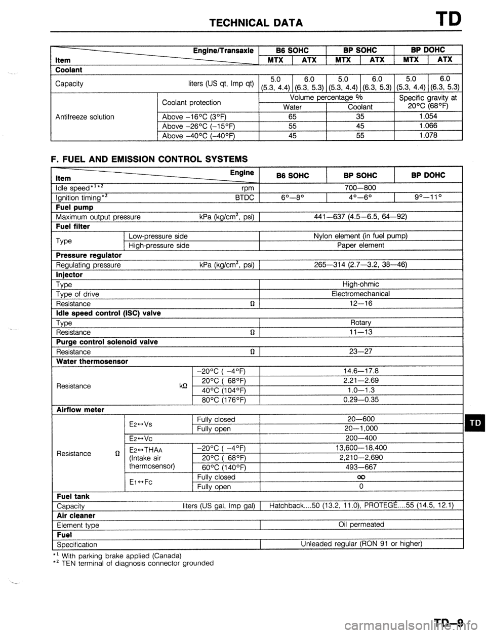
TECHNICAL DATA TD
Item
Coolant Engine/Transaxle B6 SOHC BP SOHC BP DOHC
MTX 1 ATX 1 MTX 1 ATX 1 MTX 1 ATX
Capacity
liters tus qt, Imp qt) (5Z.4) (8.E.3) (5&4) (SE.3) (5.?i.4) (S.E.3)
Coolant protection Volume percentage %
Specific gravity at
Water Coolant 20% (68OF)
Antifreeze solution Above -16OC (3OF)
65 35 1.054
Above -26OC (-15OF) 55 45 1.066
I Above -4OOC (-40°F) 45 55
1.078
F. FUEL AND EMISSION CONTROL SYSTEMS Item
idle speed*‘**
Ignition timing** Fuel pump
Maximum output pressure Fuel filter Engine
B6 SOHC BP SOHC BP DOHC
vm 700-800
BTDC 6O--8O 4O---6O 90-l 10
kPa (kg/cm*, psi) 1 441-637 (4.5-6.5, 64-92) ‘Type
Low-pressure side Nylon element (in fuel pump)
High-pressure side Paper element Pressure regulator
Regulating pressure kPa (kg/cm*, psi) 1 265-314 (2.7-3.2, 38-46) Injector
Type
High-ohmic
Type of drive Electromechanical
Resistance n 12-16 Idle speed control (ISC) valve
Type
Rotary
Resistance n ] 11-13 Purge control solenoid valve
Resistance n 1 23-27 Water thermosensor
-20°C( -4OF) 14.6-17.8
Resistance k6 20°C( 68QF) 2.21-2.69
40% (104OF) 1.0-l .3
80°C(1760F) 0.29-0.35 Airflow meter
E2++Vs Fully closed 20-600 q D Fully open 20-l ,000
E~HVC 200-400
Resistance g Ez++THAA -2O%(-4OF) 13,600-18,400
(Intake air 20%( 68OF) 2,210-2,690
thermosensor)
60°C(1400F) 493-667
Eic*Fc Fully closed 00
Fully open 0 Fuel tank
Capacity liters (US gal, Imp gal) I
Hatchback 50 (13.2, 11.0) PROTEGE . . . . 55 (14.5, 12.1) Air cleaner
Element type Oil permeated Fuel
Specification Unleaded regular (RON 91 or higher)
*’ With parking brake applied (Canada)
*’ TEN terminal of diagnosis connector grounded
TD-9
Page 1032 of 1164

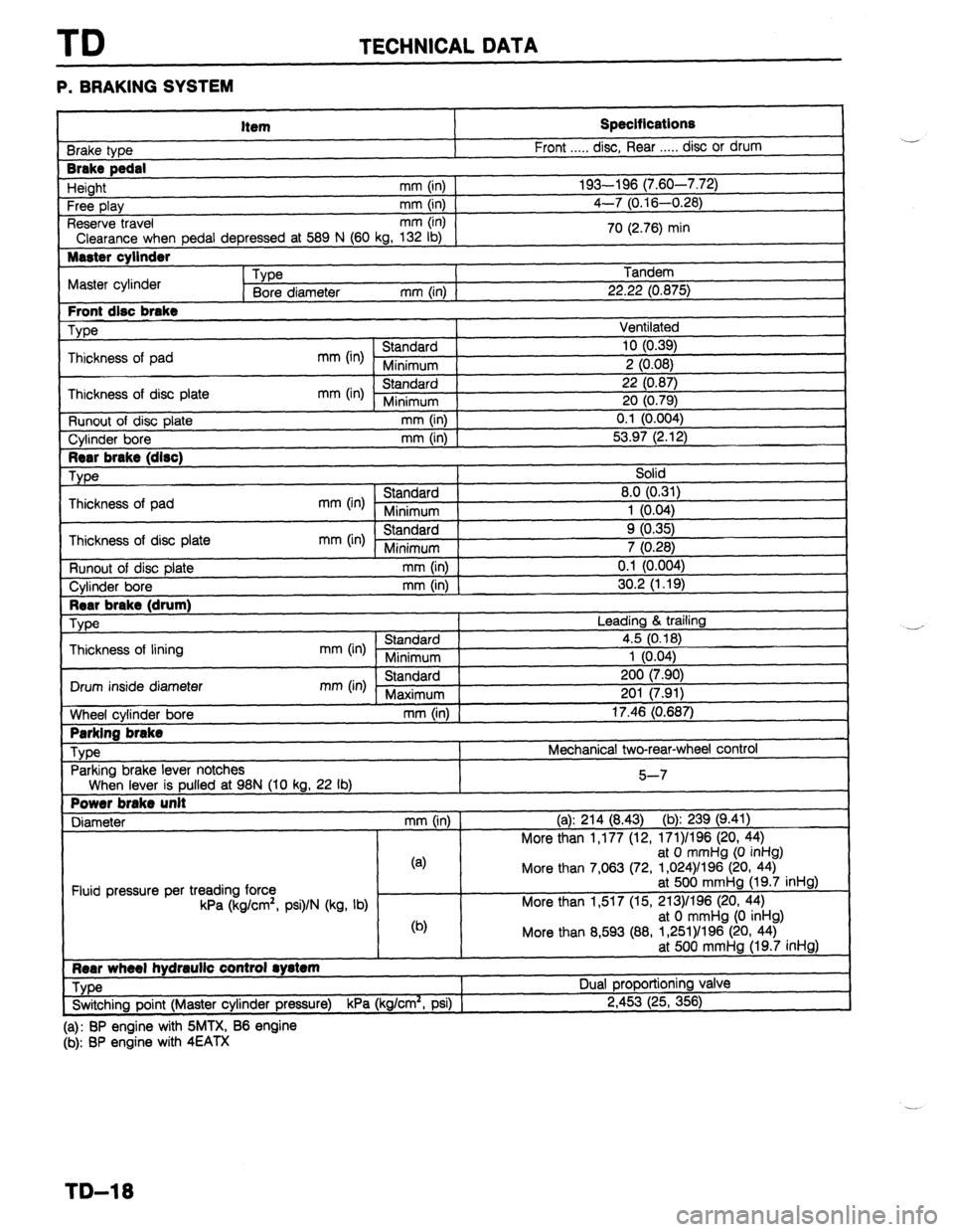
TD TECHNICAL DATA
P. BRAKING SYSTEM
Item
3rake type
Brake pedal
Height mm (in)
Free play mm (in)
Reserve travel mm (in)
Clearance when pedal depressed at 589 N (60 kg, 132 lb)
Master cylinder
Type
Master cylinder
Bore diameter mm (in) 1
Front disc brake
We
Thickness of pad
mm (in) Standard
Minimum
Thickness of disc plate
mm (in) Standard
Minimum
Runout of disc plate mm (in)
Cylinder bore
mm (in) Specifications
Front . . . . . disc, Rear . . . . . disc or drum
193-196 (7.60-7.72)
4-7 (0.16-0.28)
70 (2.76) min
Tandem
22.22 (0.875)
Ventilated
10 (0.39)
2 (0.08)
22 (0.87)
20 (0.79)
0.1 (0.004)
53.97 (2.12)
Rear brake (drum)
We
Thickness of lining
I Drum inside diameter
1
tiheel cylinder bore
I Parking brake
Type
Parking brake lever notches Leading & trailing
mm (in) Standard 4.5 (0.18)
Minimum 1 (0.04)
mm (in) Standard 200 (7.90)
Maximum 201 (7.91)
mm (in) 17.46 (0.687)
Mechanical two-rear-wheel control
When lever is pulled at 98N (10 kg, 22 lb)
Power brake unit
Diameter mm (in) 5-7
(a): 214 (8.43) (b): 239 (9.41)
More than 1,177 (12, 171)/196 (20, 44)
Fluid pressure per treading force
kPa (kg/cm’, psi)/N (kg, lb) (4
@I at 0 mmHg (0 inHg)
More than 7,063 (72, 1,024)/l 96 (20, 44)
at 500 mmHg (19.7 inHg)
More than 1,517 (15, 213)/196 (20, 44)
at 0 mmHg (0 inHg)
More than 8,593 (88, 1,261)/196 (20, 44)
at 500 mmHg (19.7 inHg)
Rear wheel hydraulic control rystem
Type Dual proportioning valve
_-_.
. .- ,. . . . !
P.IF
Switching point (Master cylinder pressure)
KPa (kg/cm-, PSI) ) z,4~j3 (25, 356)
(a): BP engine with SMTX, B6 engine
(b): BP engine with 4EATX ..-
-’
TD-18
Page 1051 of 1164

PARTS
DIFFERENTIAL ..................................... Jl-52
SHIFT MECHANISM ............................. Jl-56
TRANSAXLE ............................................ Jl-8
TRANSAXLE OIL .................................... Jl-7
MANUAL TRANSAXLE (G5M-R) .................. J2-2
DIFFERENTIAL ..................................... J2-43
SHIFT MECHANISM ............................. J2-46
TRANSAXLE.. .......................................... J2-8
TRANSAXLE OIL .................................... J2-7
MOLDING, PROTECTOR, GARNISH ...........
S-42
BELTLINE MOLDING ............................. S-48
REAR WINDOW MOLDING.. ............. S-43,44
ROOF MOLDING.. .................................. S-46
SIDE PROTECTOR ................................. S-49
UPPER WINDSHIELD MOLDING,
A-PILLAR GARNISH ............................ S-42
NEUTRAL SWITCH (MTX) . . . . . . . . . . . . . . . . . . . . . . . . . . F-l 73
0
1
\_ OIL COOLER (ENGINE). ................................ D-8
OIL PAN (ENGINE) ........................................ D-9
OIL PUMP (ENGINE) ................................... D-l 3
..................................... F-l 71
OXYGEN SENSOR
P
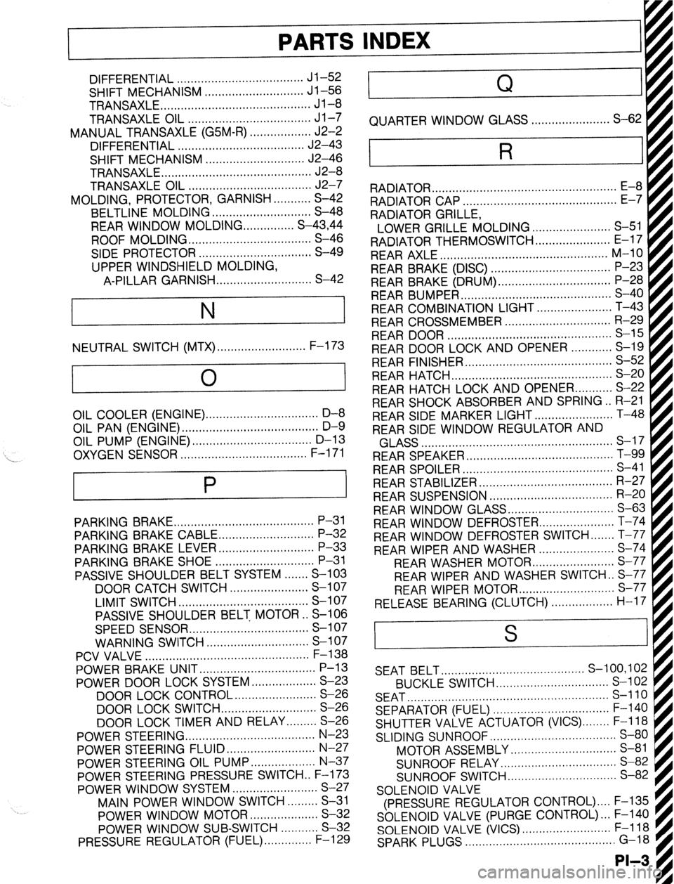
PARKING BRAKE ......................................... P-31
PARKING BRAKE CABLE ............................ P-32
PARKING BRAKE LEVER ............................ P-33
PARKING BRAKE SHOE ............................. P-31
PASSIVE SHOULDER BELT SYSTEM.. ..... S-103
DOOR CATCH SWITCH ....................... S-l 07
LIMIT SWITCH ...................................... S-l 07
PASSIVE SHOULDER BELT MOTOR.. S-106
SPEED SENSOR ................................... S-l 07
WARNING SWITCH .............................. S-l 07
PCV VALVE ................................................
POWER BRAKE UNIT ‘;--=I;;
..................................
POWER DOOR LOCK SYSTEM ................... S-23
DOOR LOCK CONTROL.. ...................... S-26
DOOR LOCK SWITCH.. .......................... S-26
DOOR LOCK TIMER AND RELAY.. ....... S-26
POWER STEERING.. .................................... N-23
POWER STEERING FLUID .......................... N-27
POWER STEERING OIL PUMP.. ................. N-37
POWER STEERING PRESSURE SWITCH . . F-l 73
POWER WINDOW SYSTEM.. .......................
S-27
MAIN POWER WINDOW SWITCH.. .......
S-31
POWER WINDOW MOTOR.. ..................
S-32
POWER WINDOW SUB-SWITCH ........... S-32
PRESSURE REGULATOR (FUEL). ............. F-l 29 . . . . . . . . , . . . . . , . RADIATOR CAP .............................................
E-7
RADIATOR GRILLE,
I
LOWER GRILLE MOLDING ....................... S-51 fl
RADIATOR THERMOSWITCH ...................... E-17 t
REAR AXLE ................................................. M-10
REAR BRAKE (DISC) ................................... P-23
REAR BRAKE (DRUM) ................................. P-28
REAR BUMPER ............................................ s-40
REAR COMBINATION LIGHT.. ....
REAR CROSSMEMBER ............................... R-29
REAR DOOR ................................................ S-l 5
REAR DOOR LOCK AND OPENER.. .
REAR FINISHER ........................................... s-52
REAR HATCH ............................................... s-20
REAR HATCH LOCK AND OPENER.. ......... S-22
REAR SHOCK ABSORBER AND SPRING.. R-21
REAR SIDE MARKER LIGHT ....................... T-48
REAR SIDE WINDOW REGULATOR AND . . . . . . . . .
AI .,.n
INDEX
Q
QUARTER WINDOW GLASS . . . . . . . . . . . . ..a........ S-62
R
RADIATOR . . . . . . . . . . . . . . . . . . . . . . . . . . . . . . . . . . . . . . . . . . . . . . . . . . . . . .
kiLA33 ........................................................ a-- I I
REAR SPEAKER ........................................... T-99
REAR SPOILER ............................................ s-41
REAR STABILIZER.. ..................................... R-27
REAR SUSPENSION .................................... R-20
REAR WINDOW GLASS ............................... S-63
REAR WINDOW DEFROSTER.. .................... T-74
REAR WINDOW DEFROSTER SWITCH ....... T-77
REAR WIPER AND WASHER ...................... S-74
REAR WASHER MOTOF
REAR WIPER AND WASHER SWITCH . . S-77
REAR WIPER MOTOR ............................ s-77
RELEASE BEARING (CLUTCH). . . . . . . . . . ..s..... H-17 I . . . . . . . . ...*. .*......*..
SEAT BELT.. ........................................ S-100,102
BUCKLE SWITCH.. ............................... S-l 02
SEAT ........................................................... s-110
SEPARATOR (FUEL) .................................. F-l 40
SHUTTER VALVE ACTUATOR (VICS) ........ F-l 18
SLIDING SUNROOF ..................................... S-80
MOTOR ASSEMBLY ............................... S-81
SUNROOF RELAY.. ................................ S-82
SUNROOF SWITCH.. .............................. S-82
SOLENOID VALVE
(PRESSURE REGULATOR CONTROL) .... F-135
SOLENOID VALVE (PURGE CONTROL). .. F-140
SOLENOID VALVE (VICS) .......................... F-l 18
SPARK PLUGS ............................................ G-18
-II__
Page 1088 of 1164

T.&condition
-t
Off
IQ”&” switch
ON
Whik cranking
lgnitlon switch ON
Test switch at “SELF-TEST”
Lamp illuminated for 3 sec. after ignition
SwiIch OFF-KIN
Lamp not illuminated after 3 sec. collect vdtaQe
ReRlar*
ve
For backup
ov
-
V%
Approx. tov
ov
4 5--5.5v With Self-
D&Q”& Check-
er and system
Vi3 st?lt?ctor Input &PJ
- -
0
0
0
0
0
0
- -
- -
0
0
c
- -
0 connectkfl to mnina
Connection to
Stoplight swtch Test condition
-L 1A
Bake pedal released
IEI
IC Main relay
(FUEL INJ relay) Brake pedal depressed
lQ”ih0” switch ON
___-- P/S Qrc?ss"re
switch
Ignition switch
(START) P/S ON at idle
P/S OFF at idle
A/C switch ON
A/C switch OFF
Cwlng fan operatng (Engine coolant tem-
perature over 97°C (207°F) or dlagnosls
connector terminal TFA grounded) (IG ON)
Fan not ooeralmg (Idle) 1D .self-mag”osls
Checker
(Monitor lamp) A!C switch
coohng fan swtctl
Test switch at “02 MONITOR” at idle
Monitor lamp ilfummated
Test switch at “02 MONITOR” at idle
Monitor lamp not illuminated
Lamp illuminated for 3 sec. after ignition
switch OFF&N
Lamp not illuminated after 3 ser.
Lamp illuminated
Lamp not #lluminated VB
Below 2.w With System
Selector test
VB swtch at
“SELF-TEST”
Eelow 2.5v
VS Blower Control
swttch Blower control switch OFF or 1 st posihon
Blower control swtch 2nd or htgher
position 1E
Malfunction indicator
lamp
NJ
Rear window defroster swtch OFF Rear wmdow
defroster switch
Headkght switch Rear window defroster Switch ON
-2-A - I
tieadlghts ON
Headlights OFF
Neutral positton or clutch pedal
depressed
OlhWS l Wiih Self-
DkQnosls
Checker and
Svstem Selector Self- Diaanosis Buzzer sounded for 3 sec. after ignition
switch OFF-ON
Buzzer not sounded after 3 set 6&w 2.5v
V8 Checke;
(Cede Number) I
ov Ignition swtch
ON NeulraliClutch
switches
. ‘.&h System
Selector test
switch at Buzzer sou”ded
1 Below 2.5V 1
VB
ov -
ov -
ov -
ov -
APprox. ov
or 4 5-5 5v
-
Approx. 2V
-
-
AQWOX. Ov
or 4 5-5 5v
-
APQ~OX 1.5V Buzzer not sounded
I VE
I
Ground (Injector)
Ground
(OUtQUt)
Ground (CPU)
Grou”d (Input)
constant
lgnlti swtch ON
klk “SELF-TEST”
ov
-
Ap~rox O.2V
- - Constant
Co”stant lgnller
1H
Constant
Igntho” swdch ON -
- D&ribulor
(Ne-sIgnal) II
1J
1K
1L
1M
1N -
fgnition switch ON
AX switch ON al idle
NC switch OFF at Idle
System Selector lest switch at
“0-z MONITOR” I -
- VB
5&w 2.w -
Vi3
VB Ignition switch
ON
System Selector test swatch at
“SELF-TEST”
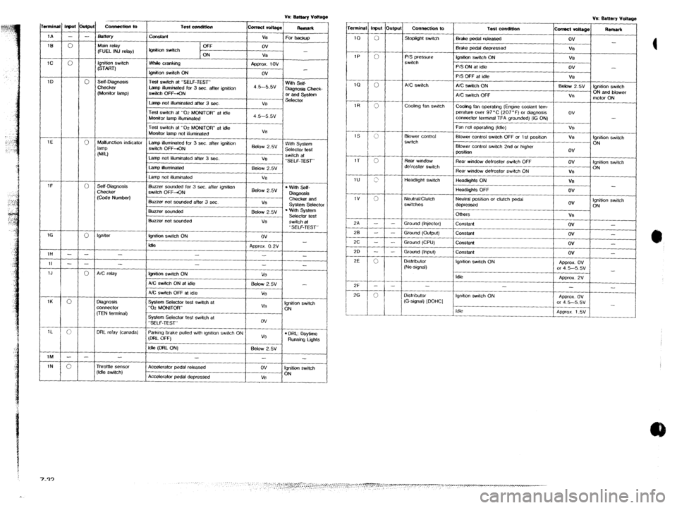
ParkIng brake pulled wth lgndlon swtch ON
(DRL OFF) ov
VB
l DRL: oaytime Running tigms
Idle (DFtL ON) Below 2.5v A/C relay
Idle
-
Ignition swtch ON
-
Distributor
(G-stgnal) [DOHC]
3ignosis
x”“ec1or
,TEN terminal) Idle
3RL relay (canada)
-
Accelerator pedal released
Accelerafor pedal depressed
-
ov
VB
-
Ignition switch
ON rhr0ttte sensor
‘Idle switch)