1992 MAZDA PROTEGE stop start
[x] Cancel search: stop startPage 697 of 1164

PARKING BRAKE SYSTEM
PARKING BRAKE SYSTEM
TROUBLESHOOTING GUIDE
Problem
Brakes do not
release
Parking brake does
not hold well Possible cause
Improper return of parking brake cable or improper ad-
justment
Excessive lever stroke
Brake cable stuck or damaged
Brake fluid or oil on pad or lining
Hardening of pad / lining surface or poor contact Remedy Repair or adjust
Adjust
Repair or replace
Clean or replace
Grind or replace Page P-32
P-31
P-32
P-i,28
ONOPX-080
PARKING BRAKE SHOE
Removal / Inspection / Installation
Disc brake
Removal and Installation (Refer to page P-23)
Inspection (Refer to page P-25)
Drum brake
Removal and Installation (Refer to page P-28)
Inspection (Refer to page P-29)
03u0Px-081
13UOPX-021
03UOPX-08
PARKING BRAKE (LEVER TYPE)
Inspection
Check that the stroke is within specification when the parking
brake lever is pulled with a force of 98 N (IO
kg, 22 lb).
Stroke: 5-7 notches
Adjustment
1. Before adjustment, start the engine and depress the brake
pedal several times while the vehicle is moving in reverse.
2. Stop the engine.
3. Remove the screw and the parking brake lever cover.
4. Remove the adjusting nut clip and turn the adjusting nut
at the front of the parking cable.
5. After adjustment, check the following points:
(1) Turn the ignition switch ON, pull the parking brake le
ver one notch, and check that the parking brake warn-
ing lamp illuminates.
(2) Verify that the rear brakes do not drag.
P-31
Page 989 of 1164

U
r
I
23UOUX-061
23UOUX-067
23UOUX-061 3
Caution
l Connect the charging hose to the air purge valve
via its tap pin side.
l Do not disconnect the charging hose or the serv-
ice container valve until the charging operation is
completed.
l Do not open the service container valve when not
used.
Charging from freon recovery and recycling system.
Connect the charging hose and stop valve to the manifold
gauge set air purge valve.
23UOUX-065
Caution
l Connect the charging hose to the air purge valve
via its tap pin side.
l Do not disconnect the charging hose or stop valve
until the charging operation is completed.
l Do not open the stop valve when not used.
4. Start the vacuum pump and open the high-and low-pressure
side valves of the manifold gauge set.
5. Start the pump and let it operate for 15 minutes.
6. Check high- and low-pressure side gauge readings. When
both of them are at 750 mmHg or more, close the manifold
gauge set valves.
7. Stop the vacuum pump and wait for about 5 minutes.
8. Verity that the low-pressure side gauge reading does not
change.
9. If the reading changes, retighten the piping connections and
repeat the evacuation operation.
10. If not changed, check for leaks (see below) and charge the
system.
u-33
Page 990 of 1164

ENGINE sro~i32 U
Leak test
1. Carry out the system evacuation and airtightness test as
described above.
2. Prepare as follows according to charging method.
Charging from service container.
Connect the refrigerant service container to the service con-
tainer valve (which is connected to the manifold gauge set air
purge valve) and open the service container.
Charging from freon recovery and recycling system.
Connect the charging valve of the system to the stop valve
(which is connected to the manifold gauge air purge valve).
23UOUX-06
23UOUX-070
I 23UOUX-072
I
80 x 0
23UOUX-07
u-34
3
3. Open the high-pressure side valve of the manifold gauge
set. Charge the system until the low-pressuer side gauge
indicates 98.1 kPa. (1 kg/cm*, 14.22 psi).
4. Close the high pressure side valve.
5. Check for leaks at the system piping joints by using a gas
leak tester.
6. If leaks are found, check the O-rings and tightening torques
at the joints. Replace or retighten as necessary.
7. If no leaks are found, fully charge the system.
Caution
l Carry out the leak test in an well-ventilated but still
air area because it is affected by moving air.
23UOUX-071
Initial charging from service container
1. Carry out the system evacuation, airtightness test, and leak
test.
2. Open the high-pressure side valve of the manifold gauge
set and charge the system as specified.
Charging amount: Approx. 400 g (14.12 oz)
3. Close the high pressure side valve.
4. Start the engine and actuate the A/C compressor.
Caution
l Do not turn the service container upside down while
charging when the engine is running.
l Do not open the high-pressure side valve while the
engine is running.
5. Open the low-pressure side valve of the manifold gauge set
and charge the system to specification.
Specified total refrigerant amount: 800 g (28.24 oz) -.
Page 991 of 1164

U
L
ENGINE STARTED
*-ENGINE STARTED
23UOUX.071
6. Close the low-pressure side valve.
7. Stop the engine.
8. Close the stop valves and the service container valve.
Caution
l Do not disconnect the stop valves or the service
container valve from the charging hoses when there
is refrigerant remaining in the hoses.
Refilling
Caution
l Do not overcharge the system.
l Note the sight glass during refilling the refrigerant.
Stop charging when no bubbles are observed in the
glass.
(Refer to page U-40).
l Care must be taken when the ambient temperature
is low. The bubbles may not be present even if the
refrigerant amount is insufficient.
1. Connect the manifold gauge set to the refrigerant system
charging valve.
(Refer to page U-32).
2. Start the engine.
3. Open the low-pressure side valve of the manifold gauge set
and charge the system as necessary.
4. Note the sight glass, and when no bubbles can be seen,
close the low-pressure side valve.
5. Stop the engine.
6. Close the stop valve and service container valve. Discon-
nect the stop valves quickly.
u-35
Page 1055 of 1164

Z
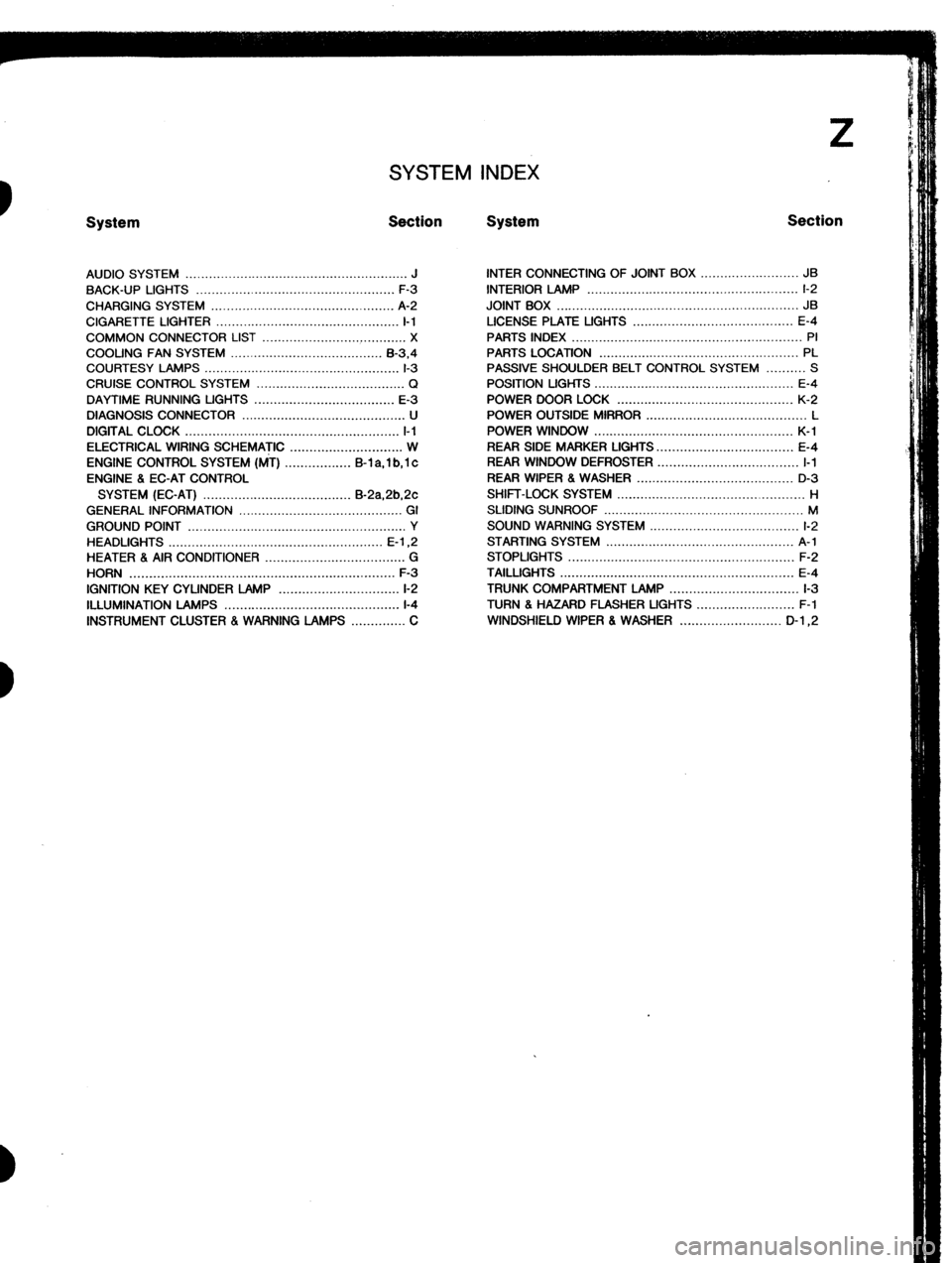
SYSTEM INDEX
System Section System Section
AUDIO SYSTEM ......................................................... J
BACK-UP LIGHTS ...................................................
F-3
CHARGING SYSTEM ............................................... A-2
CIGARETTE LIGHTER ............................................... I-1
COMMON CONNECTOR LIST ..................................... X
COOLING FAN SYSTEM ....................................... B-3.4
COURTESY LAMPS .................................................. l-3
CRUISE CONTROL SYSTEM ...................................... Q
DAYTIME RUNNING UGHTS .................................... E-3
DIAGNOSIS CONNECTOR .......................................... U
DIGITAL CLOCK ....................................................... l-l
ELECTRICAL WIRING SCHEMATIC ............................. W
ENGINE CONTROL SYSTEM (MT) ................. B-l a, 1 b, 1 c
ENGINE 8 EC-AT CONTROL
SYSTEM (EC-AT) ...................................... B-2a,2b,2c
GENERAL INFORMATION .......................................... GI
GROUND POINT ........................................................ Y
HEADLIGHTS ....................................................... E-l ,2
HEATER 8 AIR CONDITIONER .................................... G
HORN .................................................................... F-3
IGNITION KEY CYLINDER LAMP ............................... l-2
ILLUMINATION LAMPS .............................................
l-4
INSTRUMENT CLUSTER . WARNING LAMPS .............. C INTER CONNECTING OF JOINT BOX ......................... JB
INTERIOR LAMP ...................................................... l-2
JOINT BOX .............................................................. JB
LICENSE PLATE UGHTS ......................................... E-4
PARTS INDEX ........................................................... PI
PARTS LOCATION ................................................... PL
PASSIVE SHOULDER BELT CONTROL SYSTEM .......... S
POSITION LIGHTS ................................................... E-4
POWER DOOR LOCK ............................................. K-2
POWER OUTSIDE MIRROR ......................................... L
POWER WINDOW ................................................... K-l
REAR SIDE MARKER LIGHTS.. ................................. E-4
REAR WINDOW DEFROSTER .................................... I-1
REAR WIPER 8 WASHER ........................................ D-3
SHIFT-LOCK SYSTEM ................................................ H
SLIDING SUNROOF ................................................... M
SOUND WARNING SYSTEM ...................................... l-2
STARTING SYSTEM ................................................ A-l
STOPLIGHTS .......................................................... F-2
TAILLIGHTS ............................................................ E-4
TRUNK COMPARTMENT LAMP ................................. l-3
TURN 8 HAZARD FLASHER UGHTS ......................... F-l
WINDSHIELD WIPER 8 WASHER .......................... D-l ,2
Page 1066 of 1164

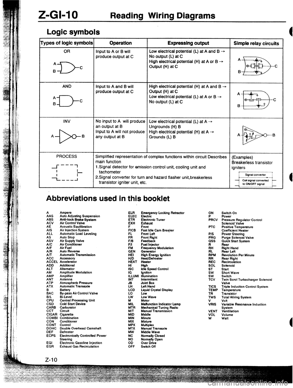
Z-GI-10 Reading Wiring Diagrams
Logic symbols
‘ypes of logic symbols Operation Expressing output Simple relay circuits
OR Input to A or 6 will Low electrical potential (L) at A and B --,
produce output at C No output (L) at C
High electrical potential (H) at A or B -+ A
A
ID- C Output (H) at C
EB Q-f2 c
B B
AND Input to A and B will High electrical potential (H) at A and B -+
produce output at C Output (H) at C
A _
A
El-- Low electrical potential (L) at A or B -+
B C
No output (L) at C
B
II!I3 Q-00-Q
C
INV No input to A will produce Low electrical potential (L) at A +
an output at B
Ungrounds (H) B
-b- Input to A will not produce High electrical potential (H) at A +
A B
any output at B Grounds (L) B A-
El
PROCESS Simplified representation of complex functions within circuit Describes (Examples)
main function
Breakerless transistor
---
-I- 1 1 Signal detector for emission control unit, cooling unit and
I igniters
- ~._..._...._._..._._..__,
--L--A tachometer
P.Signal converter for turn and hazard flasher unit,breakerless : siinalcon”elter :
i..-.--...-.........---i
transistor igniter unit, etc. --j CoIlsignal ConVerted e
--I. .‘p. Y?YT?!!9’. . _ i
Abbreviations used in this booklet
A
%J Ampere
Auto Stop
Air Supply Valve
A/C AAS
Air Conditioner Auto Adjusting Suspension
A/F Air Fuel ABS
AIR Anti-lock Brake System
Auto Reverse
A/T ACV
Automatic Transmission
ACC Air Control Vafve
Acc%K4tIory
ACCEL Accelerator
ADD AE
Additional Acoustic Equilibration
ALT Alternator
EP AIS
Amplitude Modulation Air Injection System
Amplifier ALL
ANT Antenna Automatic Load Levelino
ATP Atmospheric Pressure
ATX Automatic Tmnsaxle FR Fmnt Right ELI?
FIB Feedback
F/I Fuel Injector Emergency Locking Retractor
EN ELEC Electric
Frequency Modulation
Generator
HEI Electronic Tuner
Hiih Energy lgnitiin
HID K!
Heat/Defmster
HEAT Heater Exhaust
HI Hiih F
ISC Front
Idk Speed Contml
IG Ignition
ILLUMI Illumination FICB
INT Intermittent FL Fast Idle Cam Breaker
Fmnt Left
JB
LH Joint Box
Left Hand
:AC Battery
Bypass Air Control Valve
B/L Ei-Level
CPU Central Pmcessing Unit
CSD COM start Device
CARB Carburator
CCT Circuit
CIGAR Cigarette
COMBI Combination
CON Conditioner
CONT Control
DOHC Double Overhead Camshaft
DEF Defroster
ECPS Electronicalfy Controlfed Power
Steering
EGI Electronic Gasoline Injection
EGR Exhaust Gas Recirculation LCD Liquid Crystal Display
:i Low
Low Wave
/IL Motor
MaWunction Indicator Lamp
MTR Mechanical Tuning Radio
Mrr Manual Transmission
MID Mkfdk,
MIN Minute
MIX
MiXtUt MPX Mukiplex
MTX Manual Transaxte
K Middle Wave
Normalty Closed
too Normally Open
Over Drive
OFF Switch Off ON
FRCV
PTC
P/S
PRG
ass
ii:
RPM
EC
SOL
ST
Et TCV
TICS
TEMP
ES
V
VRIS
VENT
VOL
W Switch On
Power
Pressure Regulator Control
Solenoid Valve
Positiie Temperature
Coefficiint Heater
Power Steering
Purge Solenoid Vahe
Quick Start System
Rear
Riiht Hand
Rear Left
Revolution Per Minute
Rear Right
Recirculation
Solenoid
Start
Short Wave
Switch
~;eScml Turbocharger Solenoid
Triple Induction Control System
Temperature
Transistor
Total Wiring System
volt
Variable Resonance Induction
System
Ventilation
Volume
Wan
Page 1077 of 1164

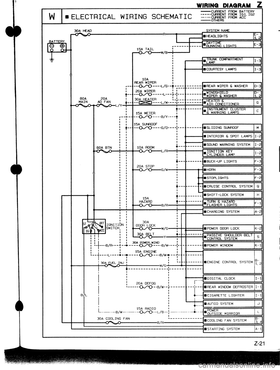
WIRINQ DIAQRAM 2
-CURRENT FROM BATTERY
W II f”‘l FCTRICAL WIRING SCHEMATIC _1_=;!:: %% :% I’*
BATTERY
P-
f
30A HEAD SYSTEM NAME
-a
c------
15A TAIL I
t-
BOA
MAIN
7 ST /;
(i
IG
:
:
1
:
I
20A ?--
AD FAN
_-. --
VW/B : I
I
I
I TRUNK COMPARTMENT
l LAMP I-3
:
I ( - n COURTESY LAMPS I-3
I
1OA
3EAR WIPER I
-- ---- L,G--/-~~-.=/zzI~~~
l REAR WIPER 6 WASHER D-3
20A WIPER
30A HEATER
,-w ---- L,w-l;c::::
I
INSTRUMENT CLUSTER
l & WARNING LAMPS C
15A METER
-----+yy _---
IOA ROOM
-1
t
----------.mBUCK-UP LIGHTS F-3
20A STOP
-G/W i - m HORN F-3
1
I
F-2
/--------%CRUISE CONTROL SYSTEM 0
. l SHIFT-LOCK SYSTEM
15A
HAZARD
I-- ------. H
--- _------
TURN 6 HAZARD
--o----B/R ; n FLASHER LIGHTS F-l
I
IPOWER DOOR LOCK K-;
’ PASSIVE SHOULDER BELT s
-mCONTROL SYSTEM
+-B/R--+-/ “Yr. I YV.LI, T.AI1a.A
---------B/W----~-i-t------. n P,-&,ER WINDOW
K-l
I
1
I I 15A ENGINE
- - I
:-,-..-L ----.- T -------- B,wl--‘-
; 30A FUEL INJ ’ a...
I- W/G ’ --------.=ENGINE CONTROL SYSTEM y-2
t ----------e--e-_ I--- ---_ .w-.w-.m-.
I
I t
: I 0
WDIGITAL CLOCK I-l
,
I 20A DEFOG I r-- WINDOW DEFROSTER 1-1
B/L I -- mCIGARETTE LIGHTER I-l
:
_ mAU’)IO SYSTEM
i----a,w-.--15A RAo1o -.-L,e-i~---i--mPOWER J
OUTSIDE MIRRIOR L
30A COOLING FAN L- ------------.
l COOLING FAN SYSTEM ;-4
B/R-p-
l STARTING SYSTEM A-l
Page 1088 of 1164

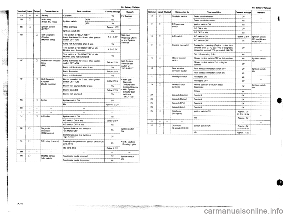
T.&condition
-t
Off
IQ”&” switch
ON
Whik cranking
lgnitlon switch ON
Test switch at “SELF-TEST”
Lamp illuminated for 3 sec. after ignition
SwiIch OFF-KIN
Lamp not illuminated after 3 sec. collect vdtaQe
ReRlar*
ve
For backup
ov
-
V%
Approx. tov
ov
4 5--5.5v With Self-
D&Q”& Check-
er and system
Vi3 st?lt?ctor Input &PJ
- -
0
0
0
0
0
0
- -
- -
0
0
c
- -
0 connectkfl to mnina
Connection to
Stoplight swtch Test condition
-L 1A
Bake pedal released
IEI
IC Main relay
(FUEL INJ relay) Brake pedal depressed
lQ”ih0” switch ON
___-- P/S Qrc?ss"re
switch
Ignition switch
(START) P/S ON at idle
P/S OFF at idle
A/C switch ON
A/C switch OFF
Cwlng fan operatng (Engine coolant tem-
perature over 97°C (207°F) or dlagnosls
connector terminal TFA grounded) (IG ON)
Fan not ooeralmg (Idle) 1D .self-mag”osls
Checker
(Monitor lamp) A!C switch
coohng fan swtctl
Test switch at “02 MONITOR” at idle
Monitor lamp ilfummated
Test switch at “02 MONITOR” at idle
Monitor lamp not illuminated
Lamp illuminated for 3 sec. after ignition
switch OFF&N
Lamp not illuminated after 3 ser.
Lamp illuminated
Lamp not #lluminated VB
Below 2.w With System
Selector test
VB swtch at
“SELF-TEST”
Eelow 2.5v
VS Blower Control
swttch Blower control switch OFF or 1 st posihon
Blower control swtch 2nd or htgher
position 1E
Malfunction indicator
lamp
NJ
Rear window defroster swtch OFF Rear wmdow
defroster switch
Headkght switch Rear window defroster Switch ON
-2-A - I
tieadlghts ON
Headlights OFF
Neutral positton or clutch pedal
depressed
OlhWS l Wiih Self-
DkQnosls
Checker and
Svstem Selector Self- Diaanosis Buzzer sounded for 3 sec. after ignition
switch OFF-ON
Buzzer not sounded after 3 set 6&w 2.5v
V8 Checke;
(Cede Number) I
ov Ignition swtch
ON NeulraliClutch
switches
. ‘.&h System
Selector test
switch at Buzzer sou”ded
1 Below 2.5V 1
VB
ov -
ov -
ov -
ov -
APprox. ov
or 4 5-5 5v
-
Approx. 2V
-
-
AQWOX. Ov
or 4 5-5 5v
-
APQ~OX 1.5V Buzzer not sounded
I VE
I
Ground (Injector)
Ground
(OUtQUt)
Ground (CPU)
Grou”d (Input)
constant
lgnlti swtch ON
klk “SELF-TEST”
ov
-
Ap~rox O.2V
- - Constant
Co”stant lgnller
1H
Constant
Igntho” swdch ON -
- D&ribulor
(Ne-sIgnal) II
1J
1K
1L
1M
1N -
fgnition switch ON
AX switch ON al idle
NC switch OFF at Idle
System Selector lest switch at
“0-z MONITOR” I -
- VB
5&w 2.w -
Vi3
VB Ignition switch
ON
System Selector test swatch at
“SELF-TEST”
ParkIng brake pulled wth lgndlon swtch ON
(DRL OFF) ov
VB
l DRL: oaytime Running tigms
Idle (DFtL ON) Below 2.5v A/C relay
Idle
-
Ignition swtch ON
-
Distributor
(G-stgnal) [DOHC]
3ignosis
x”“ec1or
,TEN terminal) Idle
3RL relay (canada)
-
Accelerator pedal released
Accelerafor pedal depressed
-
ov
VB
-
Ignition switch
ON rhr0ttte sensor
‘Idle switch)