1992 MAZDA PROTEGE oil filter
[x] Cancel search: oil filterPage 281 of 1164

OUTLINE F
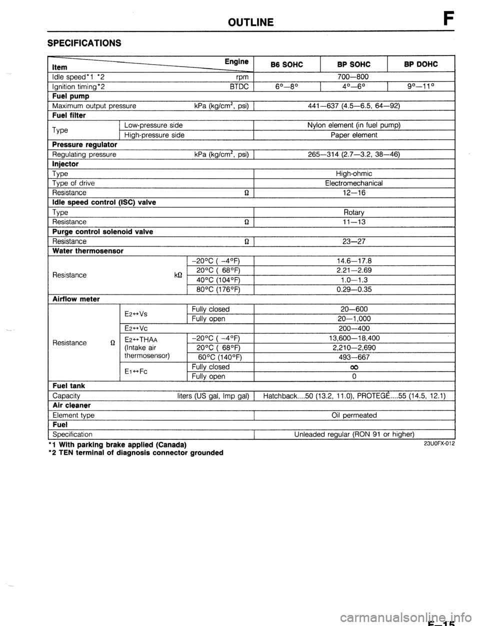
SPECIFICATIONS
Item
Idle speed*1 *2
Ignition timing*2
Fuel pump
Maximum outout Dressure Engine
rpm B6 SOHC
6O--80 BTDC 1
kPa (ka/cm’. osi1 1 BP SOHC
700-800
4O---6O BP DOHC
90-l 1 O
441-637 (4.5-6.5. 64-92) I
I Fuel filter I
Type Low-pressure side Nylon element (in fuel pump)
High-pressure side Paper element
Pressure reaulator
Regulating pressure kPa (kg/cm’, psi) 1 265-314 (2.7-3.2, 38-46)
I lniector I
Type Type of drive
Resistance
Idle speed control (ISC) valve
TvDe , ,
t Resistance
Purge control solenoid valve
Resistance
Water thermosensor n High-ohmic
Electromechanical
12-16
Rotarv
n I II-13 I
n 1 23-27
1 -20% I -4OFj 1 14.6-17.8
Resistance k62 2ooc i 68OF) 2.21-2.69
40°C (104OF) 1.0-l .3
80°C (176OF) 0.29-0.35
Airflow meter
E2++Vs
E2-Vc Fully closed
Fully open 20-600
20-l ,000
200-400
Capacity liters (US gal, Imp gal) 1 Hatchback 50 (13.2, ll.O), PROTEGE ,... 55 (14.5, 12.1)
I Air cleaner I
Element type
Fuel
Specification l
l Wlth parking brake applied (Canada)
‘2 TEN terminal of diagnosis connector grounded Oil permeated
Unleaded regular (RON 91 or higher) 23UOFX-012
F-l 5
Page 283 of 1164

OUTLINE
Component Function Remark
Engine control unit (ECU) Controls operation of the following:
(Cont’d)
1. A/C (Cut-off) 1. A/C relay
2. Fail-safe function 2. Self-Diagnosis Checker and MIL
3. Fuel injection system 3. Injector
4. idle speed control 4. Idle speed control (ISC) valve
5. Ignition timing control system 5. Igniter
6. Monitor function 6. Monitor lamp (Self-Diagnosis Checker)
7. Pressure regulator control system 7. Solenoid valve
(Pressure regulator control) (BP)
8. Purge control system 8. Purge control solenoid valve
9. VICS 9. Solenoid valve (WCS) (DOHC) Fuel filter
Filters particles from fuel Fuel pump
Provides fuel to injectors l Operates while engine running l Installed in fuel tank Igniter
Receives spark signal from ECU and gener-
ates high voltage in ignition coil Ignition switch
Engine cranking signal sent to ECU (START position)
Inhibitor switch (ATX)
Detects in-gear condition; sends signal to Switch ON in N or P range
ECU Injector
Intake air thermosensor
Idle speed control (ISC)
valve
Main relay
(FUEL INJ relay)
MIL (Malfunction
indicator lamp)
Neutral switch (MTX)
Oxygen sensor
PCV valve
P/S pressure switch
Pressure regulator
Resonance chamber
Resonance duct
Separator
Stoplight switch
Solenoid valve
(Purge control)
Shutter valve actuator
(DOHC)
Throttle body
Throttle sensor
Injects fuel into intake port l Controlled by signals from ECU
l High-ohmic injector
Detects intake air temperature; sends signal Installed on dynamic chamber
to ECU
Controls bypass air amount Controlled by duty signal from ECU
Supplies electric current to injectors, ECU,
etc.
Lamp flashes to indicate malfunction code
number of input and output devices
Detects in-gear condition; sends signal to
ECU
Detects oxygen concentration; sends signal
to ECU
Controls blowby gas introduced into engine
Detects P/S operation; sends signal to ECU
Adjusts fuel pressure supplied to injectors
Reduces intake air noise
Reduces intake air noise
Prevents fuel from flowing into charcoal
canister
Detects braking operation (deceleration),
sends signal to ECU
Controls evaporative fumes from canister to
intake manifold
Closes/opens shutter valve to improve
torque characteristics
Controls intake air quantity
l Detects throttle valve fully closed/fully
opened condition (MTX) TEN terminal grounded
Switch ON in neutral
Zirconia ceramic and platinum coating
P/S: ON when steering wheel turned right or
left
Controlled by duty signal from ECU
For Variable inertia charging system (VICS*)
Integrated throttle sensor, dashpot, and ISC
valve
l Detects throttle valve opening angle
(A-W
l Sends signals to ECU
F-l 7
Page 394 of 1164

F FUELSYSTEM
Disassembly / Assembly
1. Disassemble in the order shown in the figure.
2. Assemble in the reverse order of disassembly, referring to
Assembly Note
1. Band
2. Bracket
3. Rubber mount
OSUOFX-152
4. Fuel pump
Assembly note ,..........,....,,....,.. page F-l 28
5. Fuel filter
Assembly note
O-ring set
1. Use a new O-ring set. (O-ring, cap, and spacer)
2. Apply oil or fuel to the O-ring set before installing.
3. To confirm sealing of the O-ring, blow air through the main
pipe after assembling the fuel pump and fuel tank gauge
sender unit, and verify that no air flows past the O-ring. If
air flows through the pump, the check ball may be stuck.
Shake the fuel pump two or three times and recheck.
Fuel pump
1. After installing the fuel pump to the bracket, pull the pump
down so that it is tight against the bracket.
F-l 28
Page 1022 of 1164

TECHNICAL DATA
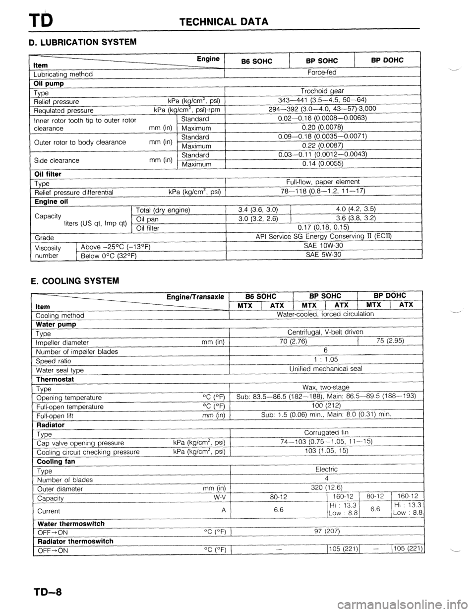
D. LUBRICATION SYSTEM
Item I I bhricatinn mothnd
Engine
B6 SOHC BP SOHC
Force-fed BP DOHC 1
Requlated pressure kPa (kg/Cm”, p
Inner rotor tooth tip to outer rotor Standard
I-‘---- -.----,
clearance mm (in) Maximum 0.20 (0.0078)
Outer rotor to body clearance mm (in) Standard 0.09-0.18 (0.0035-0.0071)
Maximum 0.22 (0.0087)
Side clearance mm (in) Standard 0.03-0.11 (O.pniq n nnn=’
Maximum n4rl ‘-
“” I r-“.““+..I,
I “. I ‘t (U.0055)
I
1
Oil filter
_ Type
Relief pressure differential
Engine oil
I
Capacity
liters (US qt, Imp qt)
Grade
I Viscosity Full-flow, paper element
kPa (kg/cm’, psi) 1 78-l 18 (0.8-I .2, 1 l-l 7) Tntal /An, nnr*inol 3.4 (3.6, 3.0) 1 4.0 (4.2, 3.5)
3.0 (3.2, 2.6) 1 3.6 (3.8, 3.2)
VII 111Lb1 0.17 (0.18, 0.15)
API Service SG Energy Conserving II (ECQ
1
SA!f InW-Xl 1~ Above -25% (-13OF _ .-.. --
I
I
number
1 Below O’C (32OF) SAE 5W-30
1
E. COOLING SYSTEM
Cooling method EnginelTransaxle
MTX ] ATX 1 MTXl
Water-cooled, forced circulation
J B6 SOHC BP SOHC BP DOHC
, ATX 1 MTX ) ATX
LThermostat
Type Opening temperature
Full-open temperature
Full-open lift
Radiator
_ Type
Cap valve opening pressure
Cooling circuit checking pressure Wax, two-stage
“C (OF) Sub: 83.5-86.5 (182--188), Main: 86.5-89.5 (188-193)
OC (OF) 100 (212)
mm (in) Sub: 1.5 (0.06) min., Main: 8.0 (0.31) min.
Corrugated fin
kPa (kg/cm2, psi) 74-103 (0.75-1.05, 11-15)
kPa (kg/cm’, psi) 103 (1.05, 15)
~..
Cooling fan
Type Electric .-
Number of blades 4
_.---- _I___-
Outer diameter mm (in) 320 (12.6)
--_ ~~-
Capacity w-v 80-12 - 160-12 80-l 2 160-12
6.6 Hi : 13.3
6.6 Hi : 13.3
Current A
Low : 8.8 Low : 8.8
_------ ._____
Water thermoswitch
“c (OF) 1
OFF-ON 97 (207)
I--.
Radiator thermoswitch
__-I____-
OFF+ON “C (OF) 1 1105 (221)( - (105 (221)
TD-8
Page 1023 of 1164

TECHNICAL DATA TD
Item
Coolant Engine/Transaxle B6 SOHC BP SOHC BP DOHC
MTX 1 ATX 1 MTX 1 ATX 1 MTX 1 ATX
Capacity
liters tus qt, Imp qt) (5Z.4) (8.E.3) (5&4) (SE.3) (5.?i.4) (S.E.3)
Coolant protection Volume percentage %
Specific gravity at
Water Coolant 20% (68OF)
Antifreeze solution Above -16OC (3OF)
65 35 1.054
Above -26OC (-15OF) 55 45 1.066
I Above -4OOC (-40°F) 45 55
1.078
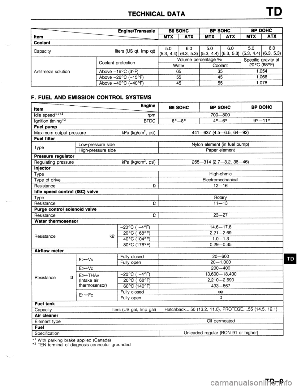
F. FUEL AND EMISSION CONTROL SYSTEMS Item
idle speed*‘**
Ignition timing** Fuel pump
Maximum output pressure Fuel filter Engine
B6 SOHC BP SOHC BP DOHC
vm 700-800
BTDC 6O--8O 4O---6O 90-l 10
kPa (kg/cm*, psi) 1 441-637 (4.5-6.5, 64-92) ‘Type
Low-pressure side Nylon element (in fuel pump)
High-pressure side Paper element Pressure regulator
Regulating pressure kPa (kg/cm*, psi) 1 265-314 (2.7-3.2, 38-46) Injector
Type
High-ohmic
Type of drive Electromechanical
Resistance n 12-16 Idle speed control (ISC) valve
Type
Rotary
Resistance n ] 11-13 Purge control solenoid valve
Resistance n 1 23-27 Water thermosensor
-20°C( -4OF) 14.6-17.8
Resistance k6 20°C( 68QF) 2.21-2.69
40% (104OF) 1.0-l .3
80°C(1760F) 0.29-0.35 Airflow meter
E2++Vs Fully closed 20-600 q D Fully open 20-l ,000
E~HVC 200-400
Resistance g Ez++THAA -2O%(-4OF) 13,600-18,400
(Intake air 20%( 68OF) 2,210-2,690
thermosensor)
60°C(1400F) 493-667
Eic*Fc Fully closed 00
Fully open 0 Fuel tank
Capacity liters (US gal, Imp gal) I
Hatchback 50 (13.2, 11.0) PROTEGE . . . . 55 (14.5, 12.1) Air cleaner
Element type Oil permeated Fuel
Specification Unleaded regular (RON 91 or higher)
*’ With parking brake applied (Canada)
*’ TEN terminal of diagnosis connector grounded
TD-9
Page 1050 of 1164

PARTS INDEX
I
CRANKSHAFT.. ....................................
I31 -64
CYLINDER BLOCK .............................. 61-60
CYLINDER HEAD..
............................... 81-54
CYLINDER HEAD GASKET .................
Bl-16
DRIVE BELT(S). ...................................... 81-5
FRONT OIL SEAL ................................ 81-23
HLA .............................................. Bl-7,20,60
OIL JET ................................................ 81-61
PISTON.. ...............................................
Bl-62
PISTON PIN..
........................................ 81-62
PISTON RING
....................................... 81-62
REAR
OIL SEAL..
................................. 81-25
TENSIONER, IDLER ............................. Bl-65
TENSIONER
SPRING ...........................
Bl-65
TIMING BELT ..................................
Bl-12,65
TIMING BELT PULLEY ........................
Bl-65
VALVE MECHANISM ........................... Bl-55
ENGINE
(BP DOHC) .................................... B2-2
CAMSHAFT ..........................................
82-58
CAMSHAFT PULLEY ...........................
B2-65
CONNECTING ROD..
........................... 82-63
CRANKSHAFT ......................................
B2-64
CYLINDER BLOCK ..............................
82-60
CYLINDER
HEAD.. ............................... B2-54
CYLINDER HEAD GASKET .................
82-16
DRIVE
BELTS.. .......................................
B2-5
FRONT
OIL SEAL ................................
82-26
H LA ..............................................
OIL JET .......................... B2-7iyL;;
......................
PISTON .................................................
B2-62
PISTON PIN ..........................................
82-62
PISTON RING..
..................................... 82-62
REAR OIL SEAL ................................... B2-28
TENSIONER, IDLER ............................. B2-65
TENSIONER SPRING ........................... B2-65
TIMING
BELT.. ................................
B2-12,65
TIMING BELT PULLEY ........................ 82-65
VALVE MECHANISM ........................... 82-55
ENGINE CONTROL UNIT (ECU) ............... F-149
ENGINE COOLANT
........................................ E-5
ENGINE OIL.. .................................................
D-7
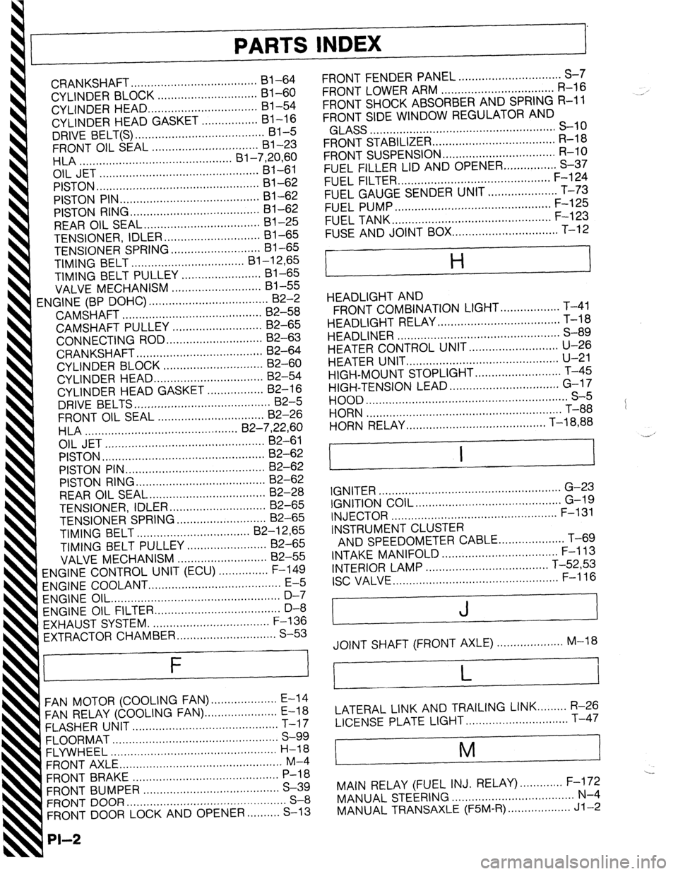
ENGINE OIL FILTER.. .................................... D-8
’ EXHAUST SYSTEM. ...................................
F-136
EXTRACTOR CHAMBER .............................. S-53
F
FAN MOTOR (COOLING FAN). ................... E-14
FAN RELAY (COOLING FAN). ..................... E-18
FLASHER UNIT ............................................
T-17
FLOORMAT ..................................................
S-99
FLYWHEEL ..................................................
H-18
FRONT AXLE .................................................
M-4
FRONT BRAKE ............................................
P-l 8
FRONT BUMPER ......................................... S-39
FRONT DOOR ................................................
S-8
FRONT DOOR LOCK AND OPENER ..........
S-13
PI-2
FRONT FENDER PANEL ............................... S-7
FRONT LOWER ARM .................................. R-16
FRONT SHOCK ABSORBER AND SPRING R-11
FRONT SIDE WINDOW REGULATOR AND
GLASS ........................................................ S-10
FRONT STABILIZER..
................................... R-l 8
FRONT SUSPENSION .................................. R-l 0
FUEL FILLER LID AND OPENER..
.............. S-37
FUEL FILTER .............................................. F-l 24
FUEL GAUGE SENDER UNIT ..................... T-73
FUEL PUMP ............................................... F-125
FUEL TANK
................................................ F-123
FUSE AND JOINT BOX.. .............................. T-12
H
HEADLIGHT AND
FRONT COMBINATION LIGHT..
................ T-41
HEADLIGHT RELAY ..................................... T-l 8
HEADLINER ................................................. S-89
HEATER CONTROL UNIT.. ......................... U-26
HEATER UNIT
.............................................. U-21
HIGH-MOUNT STOPLIGHT
.......................... T-45
HIGH-TENSION LEAD ................................. G-l 7
HOOD ............................................................. S-5
HORN T-88
...........................................................
HORN RELAY
.......................................... T-18,88
.__. ’
I I
IGNITER .......................................................
G-23
IGNITION COIL.. .......................................... G-19
INJECTOR .................................................. F-l 31
INSTRUMENT CLUSTER
AND SPEEDOMETER CABLE
.................... T-69
INTAKE MANIFOLD ................................... F-113
INTERIOR LAMP ..................................... T-52,53
ISC VALVE.. ................................................ F-l 16
J
JOINT SHAFT (FRONT AXLE) .................... M-18
L
LATERAL LINK AND TRAILING LINK.. ....... R-26
LICENSE PLATE LIGHT.. ............................. T-47
i
M
I
---
MAIN RELAY (FUEL INJ. RELAY). ............ F-172
MANUAL STEERING ..................................... N-4
MANUAL TRANSAXLE (F5M-R). .................. Jl-2