Page 394 of 1164
F FUELSYSTEM
Disassembly / Assembly
1. Disassemble in the order shown in the figure.
2. Assemble in the reverse order of disassembly, referring to
Assembly Note
1. Band
2. Bracket
3. Rubber mount
OSUOFX-152
4. Fuel pump
Assembly note ,..........,....,,....,.. page F-l 28
5. Fuel filter
Assembly note
O-ring set
1. Use a new O-ring set. (O-ring, cap, and spacer)
2. Apply oil or fuel to the O-ring set before installing.
3. To confirm sealing of the O-ring, blow air through the main
pipe after assembling the fuel pump and fuel tank gauge
sender unit, and verify that no air flows past the O-ring. If
air flows through the pump, the check ball may be stuck.
Shake the fuel pump two or three times and recheck.
Fuel pump
1. After installing the fuel pump to the bracket, pull the pump
down so that it is tight against the bracket.
F-l 28
Page 401 of 1164
PRESSUREREGULATORCONTROLSYSTEM F
03UOFX-17
*
03UOFX-14!
OSUOFX-17
SOLENOID VALVE (PRESSURE REGULATOR CONTROL)
Inspection
On-vehicle
1. Start the engine and run it at idle.
2. Disconnect the vacuum hose (Orange) from the pressure
regulator. Verify that vacuum is felt.
3. Ground the solenoid valve terminal-wire G/O with a jumper
wire. Verify that no vacuum is felt.
4. If vacuum exists, check the solenoid valve.
Solenoid Valve
1. Disconnect the vacuum hose from the solenoid valve and
vacuum pipe.
2. Blow through the solenoid valve from port @
3. Verify that air flows from port @.
4. Disconnect the solenoid valve connector.
5. Connect battery voltage and a ground to the terminals of
the solenoid valve.
6. Blow through the solenoid valve from the port @.
7. Verify that air flows from the valve air filter.
8. If not as specified, replace the solenoid valve.
F-l 35
Page 1023 of 1164

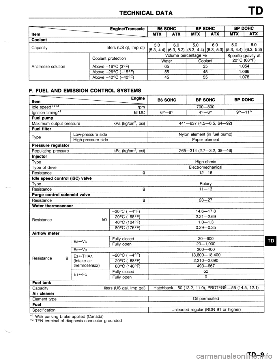
TECHNICAL DATA TD
Item
Coolant Engine/Transaxle B6 SOHC BP SOHC BP DOHC
MTX 1 ATX 1 MTX 1 ATX 1 MTX 1 ATX
Capacity
liters tus qt, Imp qt) (5Z.4) (8.E.3) (5&4) (SE.3) (5.?i.4) (S.E.3)
Coolant protection Volume percentage %
Specific gravity at
Water Coolant 20% (68OF)
Antifreeze solution Above -16OC (3OF)
65 35 1.054
Above -26OC (-15OF) 55 45 1.066
I Above -4OOC (-40°F) 45 55
1.078
F. FUEL AND EMISSION CONTROL SYSTEMS Item
idle speed*‘**
Ignition timing** Fuel pump
Maximum output pressure Fuel filter Engine
B6 SOHC BP SOHC BP DOHC
vm 700-800
BTDC 6O--8O 4O---6O 90-l 10
kPa (kg/cm*, psi) 1 441-637 (4.5-6.5, 64-92) ‘Type
Low-pressure side Nylon element (in fuel pump)
High-pressure side Paper element Pressure regulator
Regulating pressure kPa (kg/cm*, psi) 1 265-314 (2.7-3.2, 38-46) Injector
Type
High-ohmic
Type of drive Electromechanical
Resistance n 12-16 Idle speed control (ISC) valve
Type
Rotary
Resistance n ] 11-13 Purge control solenoid valve
Resistance n 1 23-27 Water thermosensor
-20°C( -4OF) 14.6-17.8
Resistance k6 20°C( 68QF) 2.21-2.69
40% (104OF) 1.0-l .3
80°C(1760F) 0.29-0.35 Airflow meter
E2++Vs Fully closed 20-600 q D Fully open 20-l ,000
E~HVC 200-400
Resistance g Ez++THAA -2O%(-4OF) 13,600-18,400
(Intake air 20%( 68OF) 2,210-2,690
thermosensor)
60°C(1400F) 493-667
Eic*Fc Fully closed 00
Fully open 0 Fuel tank
Capacity liters (US gal, Imp gal) I
Hatchback 50 (13.2, 11.0) PROTEGE . . . . 55 (14.5, 12.1) Air cleaner
Element type Oil permeated Fuel
Specification Unleaded regular (RON 91 or higher)
*’ With parking brake applied (Canada)
*’ TEN terminal of diagnosis connector grounded
TD-9
Page:
< prev 1-8 9-16 17-24