Page 329 of 1164
TROUBLESHOOTING GUIDE F
DAMAGE AND
DETERIORATION
Check if resistance of high-tension leads are OK Resistance: 16 kQ per 1 m (3.26 ft)
li;;g
‘&
d No
Replace
.
12 Check if resistance of ignition coil is OK Yes Go to next step c7 page G-19
Resistance (at 20°C [6SaF]):
Primary coil winding . . . . . . . . 0.61-0.99n
Secondary coil winding.... lo-16 kdl
PRIMARY COIL SECONDARY COIL
WINDING
WINDING
No
Replace
13 Check for correct engine compression Yes Go to next step u page Bl-10
92-10 No
Check engine condition ~7 page 81-10
Engine compression: 82-l 0
. BP DOHC
*Worn piston, piston rings or cylinder 663 kPa (9.0 kg/cm2, 126 psi)-300 rpm wall
l BP SOHC l Defective cylinder head gasket 634 kPa (6.5 kg/cm2, 121 psi)-300 rpm l Distorted cylinder head
l 66 l improper valve seating 932 kPa (9.5 kg/cm2, 136 psi)300 rpm *Valve sticking in guide
14 Change fuel and check if condition improves Yes Change fuel to another brand
No SOHC
Go to Step 16 DOHC
Go to next step
F-63
Page 331 of 1164

TROUBLESHOOTING GUIDE F
20 POOR ACCELERATION
DESCRIP- l Performance poor while accelerating
TION l idle condition normal [TROUBLESHOOTING HINTS)
3 Factors other than engine malfunction @ Air/Fuel mixture too lean
*Clutch slipping l Fuel line pressure decreases l ATX slipping l Fuel injection malfunction
l Brake dragging @ Poor ignition l Low tire pressure
@ Low engine compression
l Incorrect tire size @ Alcohol blended fuel used l Over-loaded
3 Low intake arr amount
*Throttle valve not open fully
*Clogging in intake air system
Check factors other than engine CT Section H
c7 Section
P
ing accelerator fully w page F-l 14
w page F-l 12
Checker with ignition switch ON w page F-83
rminal 1 F voltage w page F-150
Specification: Battery voltage
(Ignition switch ON)
W: SELF TEST c3 If OK, replace ECU w page F-149 r;3 If not OK, check wiring between
ECU and Self-Diagnosis Checker
Clearance between throttle
lever and stopper
0.1 mm (0.004 in)
l.Omm (0.039 in)
O.lmm (0.004 in)
0.6mm (0.024 in)
Page 333 of 1164
TROUBLESHOOTING GUIDE F
TEP INSPECTION ACTION
9 Check if airflow meter is OK Yes Go to next step
CT page F-168
I. Check if measuring plate moves smoothly
II. Check resistance No Repair or replace
Fc Ei Vc Ez Vs THA
WEAR AND CARBON BUILDUP
DAMAGE AND
DETERIORATION
Resistance (at 20% [68OF]):
Primary coil winding . . . . . . . . 0.81-0.99Q
Secondary coil winding.... IO-16 kQ
PRIMARY COIL SECONDARY COIL
cc;i’ page 81-10
Engine compression (Minimum):
883 kPa (9.0 kg/cm*, 128 psi)-300 rpm
834 kPa (8.5 kg/cm*, 121 psi)-300 rpm
932 kPa (9.5 kg/cm2, 135 psi)-300 rpm *Worn piston, piston rings or cylinder
l Defective cylinder head gasket l Distorted cylinder head
l improper valve seating
*Valve sticking in guide
F-67
Page 345 of 1164

ENGINE TUNE-UP F
03UOFX.051
03UOFX-051
- w4TEN I
Air Cleaner Element
Inspection
1. Check the air cleaner element for excessive dirt, damage,
or oil.
Caution
l Do not use compression air to clean the element.
2. Replace the element if necessary.
ADJUSTMENT
Preparation
1. Warm up the engine to normal operating temperature.
2. Turn all electric loads OFF.
3. Connect the
SST to the diagnosis connector.
4. Connect a timing light.
5. Connect a tachometer to the diagnosis connector
IG- ter-
minal as shown.
6. Set switch @to position 1.
7. Set TEST SW to SELF-TEST.
Note
l If the SST is not used, jump across the TEN termi-
nal and the GND terminal of the diagnosis con-
nector.
Ignition Timing
1. Perform “Preparation”. (Refer to above.)
2. Check if the timing mark (yellow) on the crankshaft pulley
and the mark on the timing belt cover are aligned.
Specification:
Engine
Ignition Timing BTDC B6 BP SOHC BP DOHC
6O-8* 4O--6O go-110
SOHC DOHC
I 03UOFX-054
3. If the marks are not aligned, loosen the distributor lock bolts,
and turn the distributor to make the adjustment.
4. Tighten the distributor lock bolts to the specified torque.
Tightening torque:
19-25 N#m (1.9-2.6 m-kg, 14-19 ft-lb)
5. Disconnect the SST.
F-79
Page 1016 of 1164

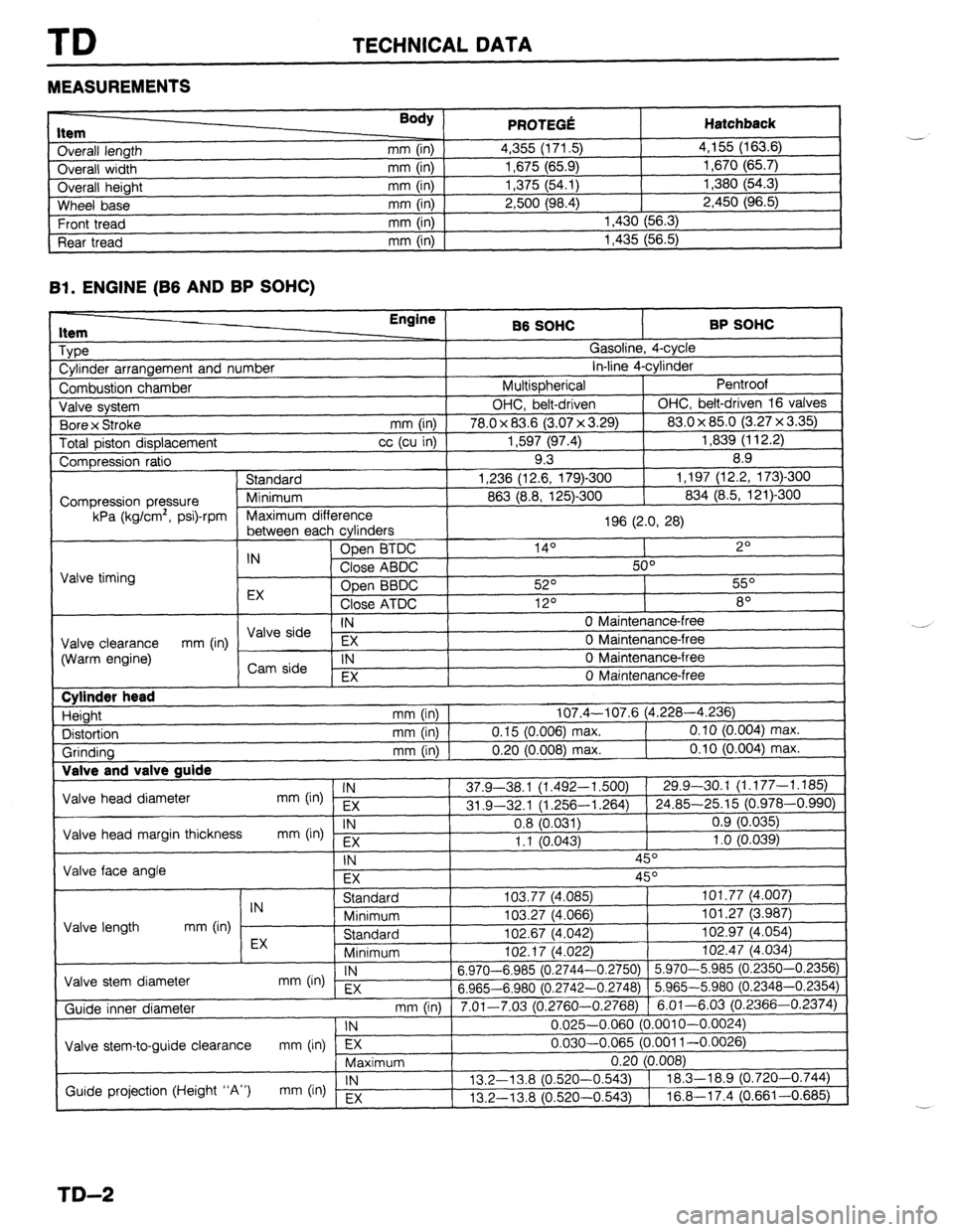
TD TECHNICAL DATA
MEASUREMENTS
I ._.____2_ nem
Overall length
Overall width
Overall height
Wheel base
Front tread
Rear tread Body ) mm (in)
mm (in)
mm (in)
mm (in)
mm (in)
mm (in) PRfWFr.f! . . ..s .-VW Hatchback 4,355 (171.5) 4,155 (163.6)
1,675 (65.9) 1,670 (65.7)
1,375 (54.1) 1,380 (54.3)
2,500 (98.4) 2,450 (96.5)
1,430 (56.3)
1,435 (56.5)
Bl. ENGINE (B6 AND BP SOHC)
1 Type
1 Cylinder arrangement and number Engine
86 SOHC BP SOHC
^ . . _
,?
I
uasollne, 4-cyw
. . *. 4
in-line 4-cyrinaer
Pentroof
1
I Combustion chamber I Multispherical
J Valve system OHC, belt-driven OHC, belt-driven 16 valves
. , I (3.07 x 3.29) 83.0 x 85.0 (3.27 x 3.35)
Total piston displacement cc (cu in) 1,597 (97.4) 1,839 (112.2)
Compression ratio 9.3 8.9
) Standard 1,236 (12.6, 179)-300 1,197 (12.2, 173)300
I
863 (8.8, 125)-300 834 (8.5, 121)300 1 Bore x Stroke
mm (in) I 78.0 x 83.6
Compression pressure
kPa (kg/cm’, psi)-rpm
E cvlinders 1 Maximum difference
196 (2.0, 28)
I
, ------- ---- -J - IN Open BTDC 14O 2O
Close ABDC 50°
Valve timing
Open BBDC 52O 55O
EX
Close ATDC 12O 8O
IN 0 Maintenance-free I \/AIo &-in --
Valve clearance EX 0 Maintenance-free
(Warm engine) mm (in) / ,,syi: 1
IN 0 Maintenance-free
I , EX 0 Maintenance-free
I Cylinder head
Height
Distortion
Grinding Valve and T _
Valve head diameter
Valve head margin thickness
Valve face angle IN mm (in) EX
IN
mm b-4 Fx mm (in) 107.4-107.6 (4.228-4.236)
mm (in) 0.15 (0.006) max. 0.10 (0.004) max.
mm (in) 0.20 (0.008) max. 0.10 (0.004) max.
37.9-38.1 (1.492-l ,500) 29.9-30.1 (1.177-1.185)
31 .Q-32.1 (1.256-l ,264) 24.85-25.15 (0.978-0.990)
0.8 (0.031) 0.9 (0.035)
1.1 10.043) 1 .o (0.039)
-, ,
\- I
IN 45O
EX 45O
I I Standard
IN
Minimum
Valve length mm (in)
EX Standard
Minimum I”L. I, \*.“cL
Valve stem diameter IN
mm On) EX 6.970-6.985 (0.2744-
6.965-6.980 (0.2742-
Guide inner diameter
I Valve stem-to-guide clearance mm (in) lTj7---- ,
Maximum 103.77 (4,085) 101.77 (4.007)
103.27 (4.066) 101.27 (3.987)
102.67 (4.042) 102.97 (4.054)
,n+ 47 IA noo
1 102.47 (4.034)
-0.2750) 5.970-5.985 (0.2350-0.2356)
-0.2748) 5.965-5.980 (0.2348-0.2354)
3.2760-0.2768) 6.01-6.03 (0.2366-0.2374)
0.025-0.060 (0.001 O-0.0024)
0.030-0.065 (0.001 l-0.0026)
-.
I
mm (in) 1 7.01-7.03 (r ‘
1 IN
Guide projection (Height “A”) IN
mm (in) Ex 13.2-l 3.8 (0.520-
13.2-13.8 (0.520-
TD-2
Page 1019 of 1164

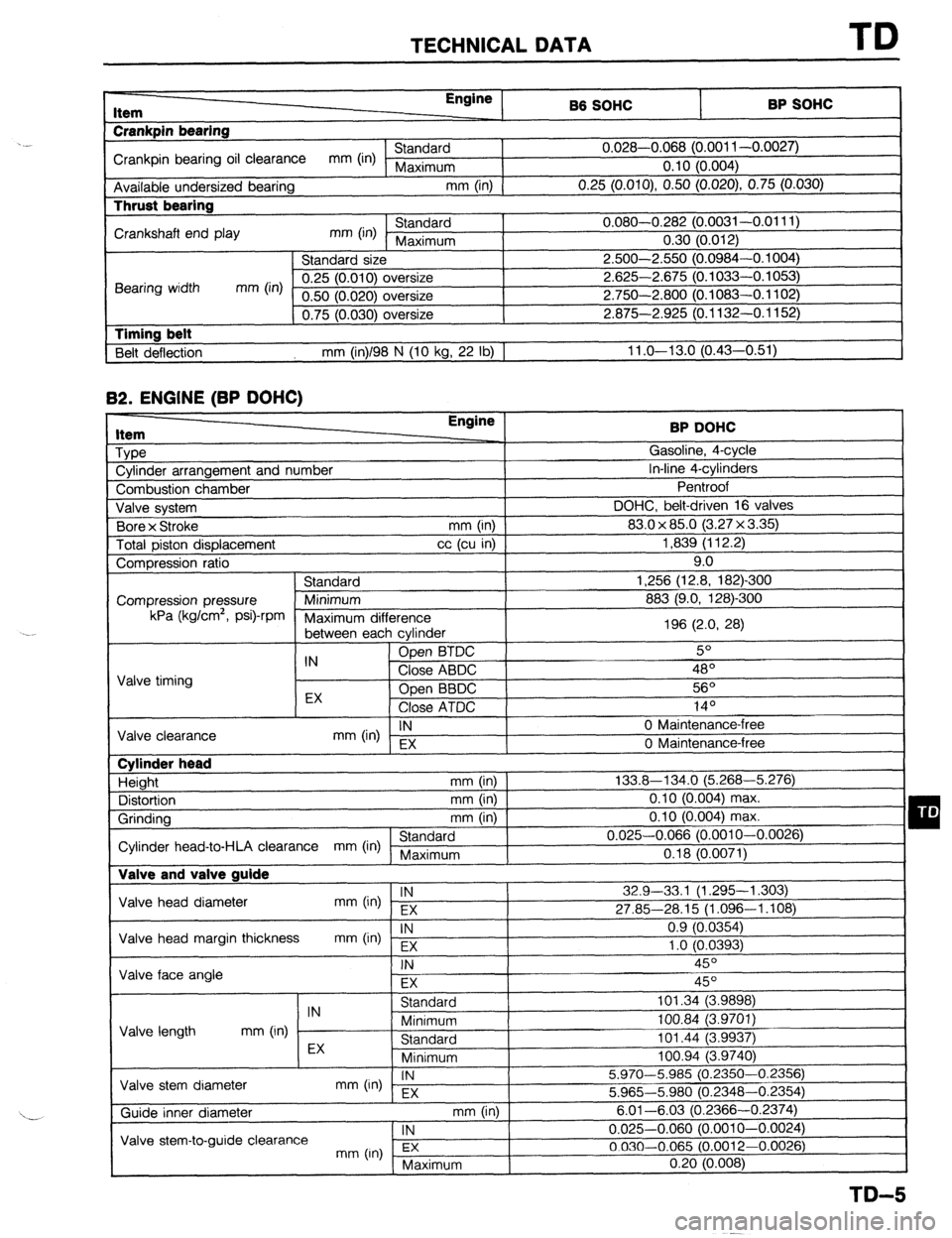
TECHNICAL DATA TD
r-
RP sm.lc: I Item
Crankpin bearing Engine
86 SOHC
I -. VW.._
Crankpin bearing oil clearance mm (in) Standard 0.028-0.068 (0.001 l-0.0027)
Maximum 0.10 (0.004)
Available undersized bearing mm (in)
0.25 (O.OlO), 0.50 (0.020) 0.75 (0.030) Thrust bearing
Crankshaft end play mm (in) Standard 0.080-0.282 (0.0031-0.0111)
Maximum 0.30 (0.012)
Standard size 2.500-2.550 (0.0984-0.1004)
Bearing width mm (in) 0.25 (0.010) oversize 2.625-2.675 (0.1033-0.1053)
0.50 (0.020) oversize 2.750-2.800 (0.1083-0.1102)
0.75 (0.030) oversize 2.875-2.925 (0.1132-0.1152)
1 Timing belt
Belt deflection mm (in)/98 N (10 kg, 22 lb) 1 11 .o-13.0 (0.43-0.51) 82.
ENGINE (BP DOHC) Item
Type
Cylinder arrangement and number BP DOHC
Gasoline, 4-cycle
In-line 4-cylinders
-. I
Combustion chamber
Valve svstem DOHC, belt-d
Bore x Stroke
Total piston displacement ventroot
riven
(3.2:
mm (in) 1 83.0 x 85.0
cc (cu in) ]
7x3.35)1 1,839 (112.2)
I 16 valves I 9.0
-300
mn Compression ratio
Standard 1,256 (12.8, 182)
Compression pressure Minimum 883 (9.0, 128)-Z kPa (kglcm2,
Psi)-rPm
Maximum dif
‘ference
between eat -, h cvlinder 196 (2.0, 28)
IN Open BTDC 5O
Valve timing Close ABDC 48’
EX Open BBDC 56O
Close ATDC .4 In
IY-
IN
mm (in) EX 0 Maintenance-l
Valve clearance
0 Maintenance-i ‘ree
‘me Cylinder head
Height mm (in)
Distortion mm (in)
Grinding mm (in)
Standard
Cylinder head-to-HLA clearance mm (in) Maximum Valve and valve guide 133.8-134.0 (5.268-5.276)
0.10 (0.004) max.
0.10 (0.004) max.
0.025-0.066 (0.0010-0.0026)
0.18 (0.0071)
Valve head diameter IN
mm (in) EX 32.9-33,l (1.295-l ,303)
27.85-28.15 (1.096-1.108)
Valve head margin thickness IN
mm On) Fx 0.9 (0.0354)
1 .o fO.0393)
1 Valve face angle . .
I
FX I I
Valve length IN
Standard 101.34 (3.9898)
mm (in) Minimum 100.84 (3.9701)
Standard 101.44 (3.9937) I -, .
I
Valve stem diameter EX
Minimum loo.94 i3.974oj
IN
mm (in) - EX 5.970-5.985 (0.2350-0.2356)
5.965-5.980 (0.2348-0.2354)
mm (in) I
. , , 6.01-6.03 (0.23 166-0.2374)
1 IN
I 0.025-0.060 (0.0010-0.0024)
3.0012-0.0026)
( Maximum 0.20 (0.008)
I
TD-5