Page 919 of 1164
INSTRUMENT CLUSTER T
INSTRUMENT CLUSTER
PREPARATION
SST
I
I
49 0839 285
Checker, fuel
thermometer For
inspection of fuel
and water
temperature
gauge
I I
I
23UOTX-038
STRUCTURAL VIEW
WITH TACHOMETER (2WD)
WITHOUT TACHOMETER (2WD)
1. Speedometer 4. Fuel gauge
Troubleshooting . . . . . . . ..*................ page T-64 Troubleshooting . . . . . . . . . . . . . . . . . . . . . . . . . . page T-64
Inspection .,.......,,.......,,...,,.......... page T-71 Inspection . . . . . . . . . . . . . . . . . . . . . . . . . . . . . . . . . . . page T-71
2. Tachometer 5. Warning and indicator
Troubleshooting ..,....................... page T-64 Inspection ,.......,,......................... page T-61
inspection . . . . . . . . . . . . . . . . . . . . . . . . . . . . . . . . . . page T-71 6. Odometer
3. Water temperature gauge 7. Tripmeter
Troubleshooting . . . . . . . . . . . . . . . . . . . . . . . . . . page T-64
Inspection .,,........,,,,......,,............ page T-72
T-63
Page 920 of 1164
2L BUZZER 2A 28 2C 2D 1A 3K l--r nnmn
I I‘ I
1C 3L 2E 2G IL iG 1F 1D tB
3F 38 3G 1E 3D
l-l rt
II l-l
l-l It II l-l 1J 11 1H
1G IF 1E 1D 1C 1B 1A 2L 2K 2J 21 2H 2G 2F 2E 2D 2C 28 2A
r-l It ,I 3L 3K 3J 31 3H 3G 3F 3E 3D 3C 3B 3A
Ter- I I minal Connected to 1 1A Combination switch
1B Ground
IC Fuel tank unit
1 ID 1 EGI control unit
I
II L 1J 1
L Ter-
minal Connected to
2A Speed sensor output
28 Light switch (high beam)
2C Turn switch (L)
20 Turn switch (R)
2E Ground
2F Ground
2L 1 IGI battery Ter-
minal Connected to
3A
38 Alternator
3c
30 Oil pressure switch
3E
3F Parking brake switch, Brake fluid switch
3G Passive shoulder belt control unit
3H h
I 31
3J
3K
IG2 battery
3L Water temperature gauge unit
Page 924 of 1164

T INSTRUMENT CLUSTER
Symptom: Fuel gauge does not operate.
SMUOTX-077 -_d
,
1
OBUOTX-186
W/ TACHO W/O TACHO
7R 7cl
9MUOTX-079
23UOTX-04:
WI TACHO W/O TACHO
7Q 7cl
Step 1
1. Disconnect the connector from the fuel gauge sender unit.
2. Connect the red lead of the SST to the terminal-wire (Y) and
the black lead to a body ground.
3. Set the SST to the resistance values shown in the figure.
4. Turn the ignition switch ON, and verify that the needle indi-
cates the correct values.
Indicates correct Action
Yes Replace fuel gauge sender unit (in fuel tank)
/
No Go
to Step 2
Caution
l Continue the above checks for at least two minutes
each to correctly judge the condition.
l The allowable indication error is twice the width of
the needle.
Step 2
1. Remove the instrument cluster. (Refer to page T-69.)
2. Apply battery voltage to terminal 2L and ground terminal 2E.
3. Connect the red lead of the SST to terminal 1C and the
black lead to a negative battery terminal.
4. Set the SST to the resistance values shown in the figure.
5. Verify that the needle indicates the correct values.
Indicates correct Action
Yes Repair wiring harness
(Instrument cluster - fuel gauge sender unit)
No Replace fuel gauge sender unit
Caution
. Continue the above checks for at least two minutes
each to correctly judge the condition.
l The allowable indication error is twice the width of
the needle. .-/
Page 927 of 1164

INSTRUMENT CLUSTER T
(For Canada)
(For USA)
11
OSUOTX-114
Standard Indication
(rpm)
1,000
2,000
3,000
4,000
5,000
6,000
7,000
8,000 Allowable range
@pm)
880-l ,060
1,970-2,150
3,000-3,180
4,000-4,240
5,000-5,300
6,000-6,360
7.000-7.420
8:600-8:480
03UOTX-11 5
I 23UOTX-044 WI TACHO WIO MACHO
32.50
ssn
9MUOTX-087
Inspection
Speedometer
1. Using a speedometer tester, check the speedometer for ai-
lowable indication error, and check the operation of the
odometer. Replace if necessary.
2. Check the speedometer for fluctuation and/or abnormal
noise.
Caution
l If significant fluctuation occurs or the speedome-
ter does not move at all, remove the speedometer
cable. If it is normal, replace the speedometer as-
sembly.
l Tire wear and improper inflation will Increase
speedometer error.
Tachometer
1. Connect a test tachometer to the engine, and start the
engine.
2. Check the tachometer for allowable indication error. Replace
if necessary.
Caution
l When removing or installing the tachometer, do not
drop it or subject it to sharp shocks.
Fuel gauge
1. Remove the instrument cluster. (Refer to page T-69.)
2. Apply battery voltage to terminal 2L and ground terminal 2E.
3. Connect the red lead of the
SST to terminal 1C and the
black lead to a negative battery terminal.
4. Set the
SST to the resistance values shown in the figure.
5. Verify that the needle indicates the correct values.
Caution
l Continue the above checks for at least two minutes
each to correctly judge the condition.
l The allowable indication error is twice the width of
the needle.
T-71
Page 929 of 1164
INSTRUMENT CLUSTER T
03UOTX-12
32.51
2
03UOTX-122
PROTEGli
32.58
FUEL GAUGE SENDER UNIT
Removal / Installation
1. Remove the fuel hose from the fuel tank.
2. Remove the bolt and fuel tank.
3. Remove the fuel gauge sender unit.
4. Install in the reverse order of removal.
Inspection
1. Remove the fuel tank gauge unit. (Refer to Section F.)
2. Disconnect the fuel gauge sender unit connector.
3. Check resistance while slowly moving the unit arm from point
F to point E.
4. If not correct, replace the fuel gauge sender unit.
T-73
Page 953 of 1164
AUDIO T
Noise Suppression Chart
Cause
‘uel pump noise Remedy Move speaker wiring away from fuel pump wire.
REAR HARNESS FUEL
PUMP
Wotor noise
Wiper, washer, power
window, for example) 1. Check grounding.
2. Install condensers to motor circuit.
Turn signal noise Connect condenser (0.5 pF) to power line of filter unit. Note
CONDENSER
4lternator noise
l Condenser should be placed near flasher unit.
Connect condenser (0.5 pF) near alternator.
TO RADIO
CONDENSER
97UOTX-1
T-97
Page 1015 of 1164

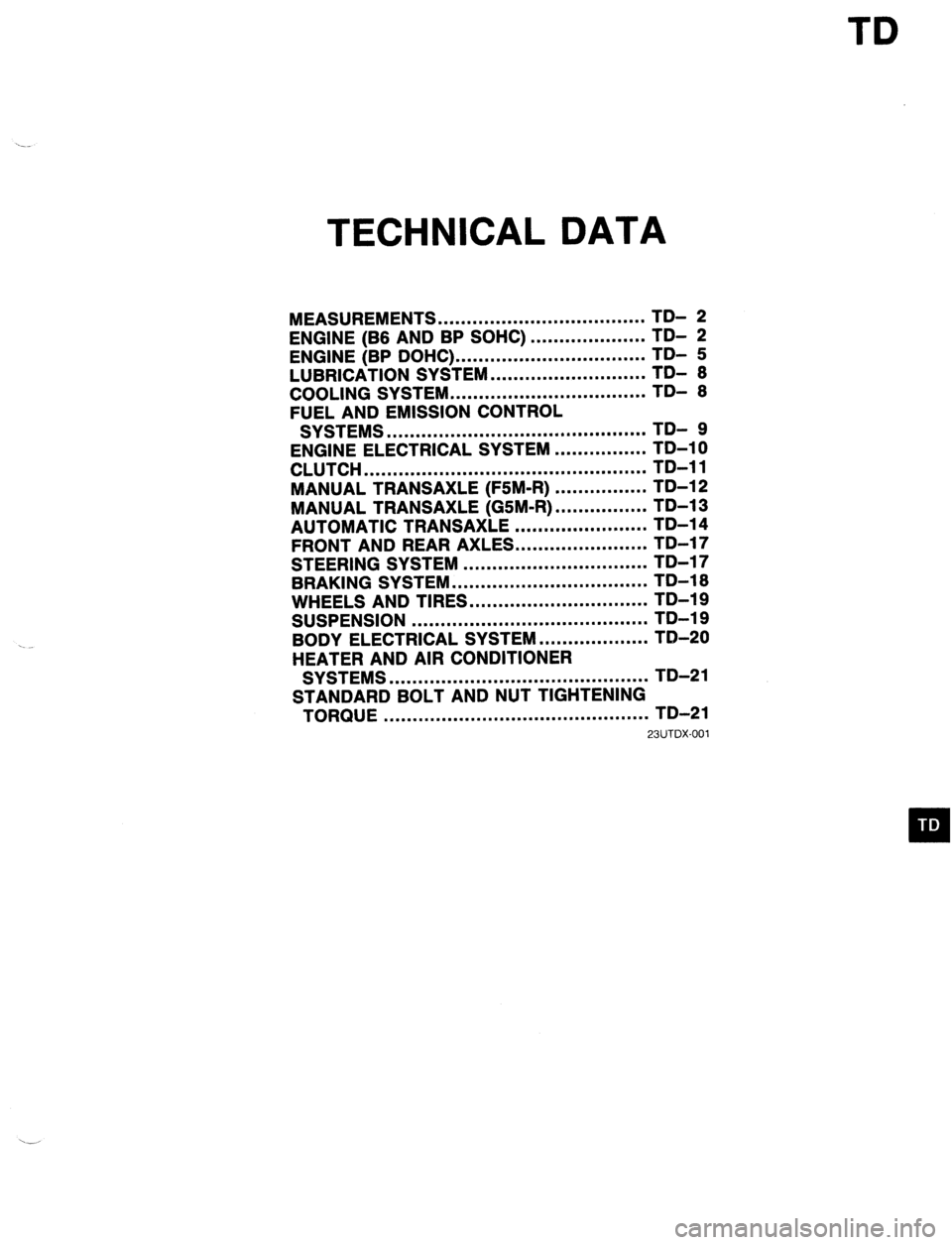
TD
TECHNICAL DATA
MEASUREMENTS .................................... TD- 2
ENGINE (B6 AND BP SOHC)
ENGINE (BP DOHC) ... .................................................. ;;- f
LUBRICATION SYSTEM ........................... TDI 6
COOLING SYSTEM .................................. TD- 6
FUEL AND EMISSION CONTROL
SYSTEMS ............................................. TD- 9
ENGINE ELECTRICAL SYSTEM ................ TD-10
CLUTCH ................................................. TD-11
MANUAL TRANSAXLE (F5M-R) ................ TD-12
MANUAL TRANSAXLE (GSM-R) ................ TD-13
AUTOMATIC TRANSAXLE ....................... TD-14
FRONT AND REAR AXLES.. .....................
STEERING SYSTEM ................................ ;;-;;
-
BRAKING SYSTEM .................................. TD-16
WHEELS AND TIRES ............................... TD-19
SUSPENSION ......................................... TD-19
BODY ELECTRICAL SYSTEM ................... TD-20
HEATER AND AIR CONDITIONER
SYSTEMS ............................................. TD-21
STANDARD BOLT AND NUT TIGHTENING
TORQUE .............................................. TD-21
23UTDX-001
Page 1023 of 1164

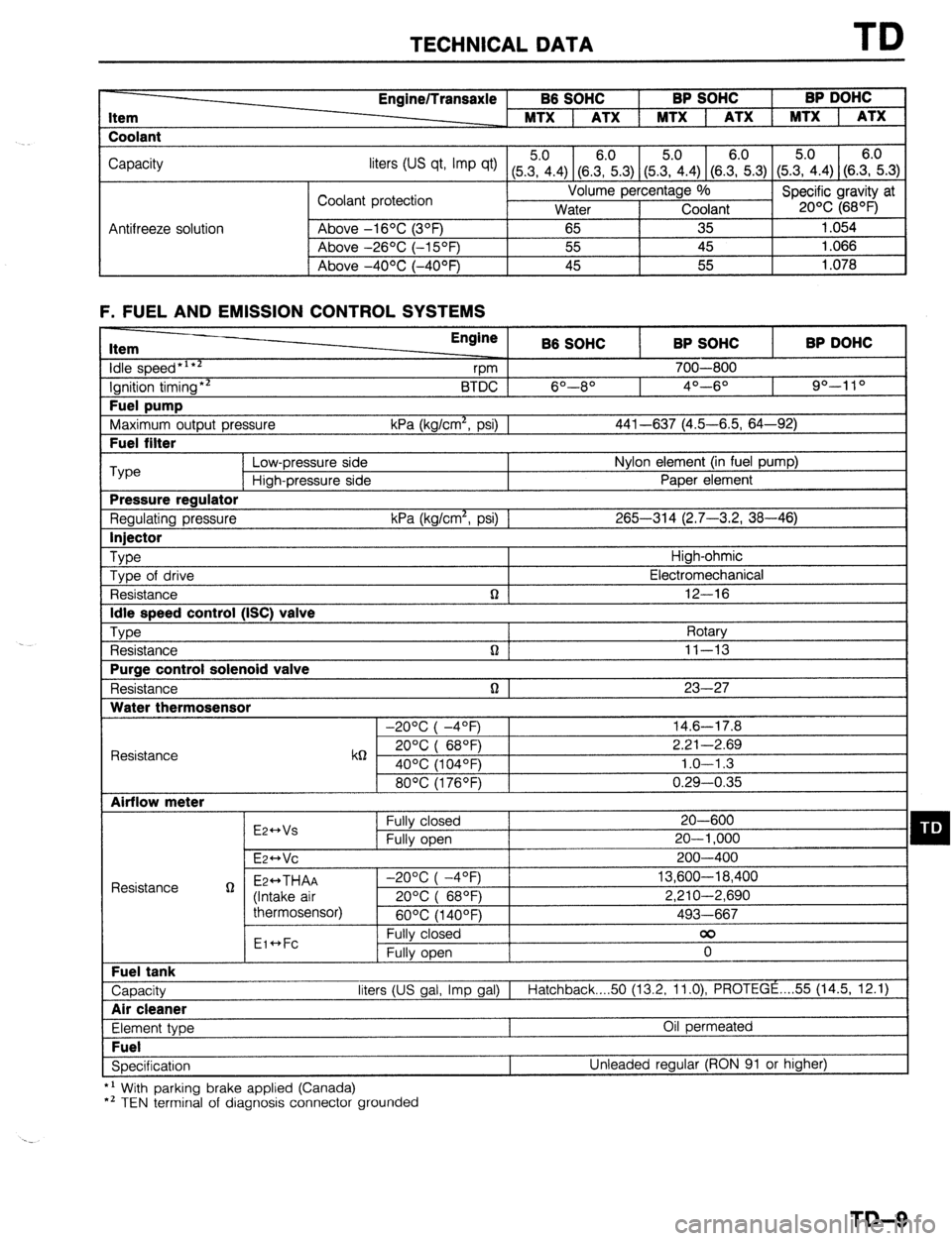
TECHNICAL DATA TD
Item
Coolant Engine/Transaxle B6 SOHC BP SOHC BP DOHC
MTX 1 ATX 1 MTX 1 ATX 1 MTX 1 ATX
Capacity
liters tus qt, Imp qt) (5Z.4) (8.E.3) (5&4) (SE.3) (5.?i.4) (S.E.3)
Coolant protection Volume percentage %
Specific gravity at
Water Coolant 20% (68OF)
Antifreeze solution Above -16OC (3OF)
65 35 1.054
Above -26OC (-15OF) 55 45 1.066
I Above -4OOC (-40°F) 45 55
1.078
F. FUEL AND EMISSION CONTROL SYSTEMS Item
idle speed*‘**
Ignition timing** Fuel pump
Maximum output pressure Fuel filter Engine
B6 SOHC BP SOHC BP DOHC
vm 700-800
BTDC 6O--8O 4O---6O 90-l 10
kPa (kg/cm*, psi) 1 441-637 (4.5-6.5, 64-92) ‘Type
Low-pressure side Nylon element (in fuel pump)
High-pressure side Paper element Pressure regulator
Regulating pressure kPa (kg/cm*, psi) 1 265-314 (2.7-3.2, 38-46) Injector
Type
High-ohmic
Type of drive Electromechanical
Resistance n 12-16 Idle speed control (ISC) valve
Type
Rotary
Resistance n ] 11-13 Purge control solenoid valve
Resistance n 1 23-27 Water thermosensor
-20°C( -4OF) 14.6-17.8
Resistance k6 20°C( 68QF) 2.21-2.69
40% (104OF) 1.0-l .3
80°C(1760F) 0.29-0.35 Airflow meter
E2++Vs Fully closed 20-600 q D Fully open 20-l ,000
E~HVC 200-400
Resistance g Ez++THAA -2O%(-4OF) 13,600-18,400
(Intake air 20%( 68OF) 2,210-2,690
thermosensor)
60°C(1400F) 493-667
Eic*Fc Fully closed 00
Fully open 0 Fuel tank
Capacity liters (US gal, Imp gal) I
Hatchback 50 (13.2, 11.0) PROTEGE . . . . 55 (14.5, 12.1) Air cleaner
Element type Oil permeated Fuel
Specification Unleaded regular (RON 91 or higher)
*’ With parking brake applied (Canada)
*’ TEN terminal of diagnosis connector grounded
TD-9