1992 BMW 325i air flow sensor
[x] Cancel search: air flow sensorPage 291 of 759

Brake
rotor,
removing
and
installing
.
.
.
.
.
.
.
.
340-7
MASTER
CYLINDER
............
.
.
.
.
.
.
.340-7
Master
cylinder,
removing
and
installing
.
...
.
340-7
GENERAL
TROUBLESHOOTING
WARNING
-
"
Although
semi-metallic
and
metallic
Brake
friction
materials
in
Brake
pads
or
shoes
no
longer
con-
tain
asbestos,
they
produce
dangerous
dust
.
"
Brake
fluid
is
poisonous,
highly
corrosive
and
dangerous
to
the
environment
Wear
safety
glasses
and
rubber
gloves
when
working
with
Brake
fluid
.
Do
not
siphonBrake
fluid
with
your
mouth
.
Immediately
clean
away
any
fluid
spilled
on
painted
surfaces
and
wash
with
water,
asBrake
fluid
will
remove
paint
.
"
Always
use
new
Brake
fluid
froma
fresh,
un-
opened
container
.
Brake
fluid
will
absorb
mois-
ture
from
the
air
.
This
canlead
to
corrosion
problems
in
the
brakingsystem,
and
will
also
low-
er
the
Brake
fluid's
boiling
point
.
Dispose
of
Brake
fluid
properly
.
"
Do
notreuse
self-locking
nuts,bolts
or
fasteners
.
They
are
designed
to
be
used
only
once
and
may
failif
reused
.
Always
replace
them
with
new
self-
locking
fasteners
.
BMW
E36
models
areequipped
with
vacuum
power-assist-
ed
four-wheel
disc
brakes
with
an
integral
Antilock
Brake
Sys-
tem
(ABS)
.
Single-pistoncalipers
act
on
solid
or
vented
front
rotors
and
solid
rear
rotors
.
A
brake
pad
wear
sensor
for
each
axle
indicates
when
brake
padsneed
replacement
.
The
dual
drum-type
parking
brakesystem
is
integrated
with
the
rear
brake
rotors
.
NOTE-
M3
models
havevented
directional
Brake
rotors
on
the
rearaxle
as
well
ason
the
front
.
340
Brakes
BRAKES
340-1
GENERAL
.
.
.
.
.
.
.........
.
.
.
..........
340-1
BRAKE
BOOSTER
.........
.
.
.
.
.
...
.
.
.
.
340-8
TROUBLESHOOTING
.......
.
......
.
...
340-1
Brake
booster,
removing
and
installing
....
.
.
340-8
PARKING
BRAKE
.
.....
.
...
.
.
.
.....
.
.
.
340-10
BLEEDING
BRAKES
.
.
.
.
.
.
.
.
..........
340-3
Parking
brake,adjusting
.
.
.
.
.
.
.
.
.
.
.....
.
340-10
Pressure
bleeding
brakes
Parking
brake
shoes,
removing
and
installing
.
340-11(except
cars
with
AST)
.
.
.
.
.
.
.
.
.
...
.
.
.
.
.340-3
Parking
Brake
cable,
replacing
.
.
.
.
.
.
.
.
.
.
.
.
340-11
BRAKE
PADS,
CALIPERS,
ANTILOCK
BRAKE
SYSTEM
(ABS)
.
.
.
.340-11
AND
ROTORS
..........
.
.......
.
.
.
.
.
.
.
340-3
ABS
System
Inspection
.
...
.
.......
.
.
.
..
340-12
Brake
pads,
replacing
............
.
.
.
.
.
.
.
340-4
ABS
wheel
speed
sensors,
replacing
.
.
.
.
..
340-12
Brake
caliper,
removing
and
installing
.
..
..
.
340-6
TABLES
a
.
Brake
System
Troubleshooting
.....
...
.
.
.....
.340-2
b
.
Brake
Rotor
Reconditioning
Specifications
.
.....
.340-7
Brakeperformance
is
mainly
affected
by
three
things
:
the
leve¡
and
condition
of
the
brake
fluid,
the
system's
abilíty
to
create
and
maintain
hydraulic
pressure,
and
the
condition
of
the
friction
components
.
Air
in
the
Brake
fluid
will
make
the
Brake
pedal
feel
spongy
during
braking
or
will
increase
the
Brake
pedalforce
required
to
stop
.
Fluid
contaminated
by
moisture
or
dirt
can
corrode
the
system
.
Inspect
the
Brake
fluid
inside
the
reservoir
.
Ifit
is
dirty
or
murky,
or
is
over
a
year
old,
the
fluid
should
be
replaced
.
Visually
check
the
hydraulic
system
startingat
the
master
cylinder
.
To
check
the
function
of
the
master
cylinder
hold
the
brake
pedal
down
hard
with
the
engine
running
.
The
pedal
should
feelsolid
and
stay
solid
.
If
the
pedal
slowly
falls
to
the
floor,
either
the
master
cylinder
is
leaking
internally,
or
fluid
is
leaking
externally
.
If
no
leaks
canbe
found,
the
master
cylin-
der
is
faulty
and
should
be
replaced
.
Check
all
Brake
fluid
lines
and
couplings
for
leaks,
kinks,
chafing
and
corrosion
.
Check
the
Brake
booster
by
pumping
the
Brake
pedal
ap-
proximately
10
times
with
the
engine
off
.
Hold
the
pedal
down
and
start
the
engine
.
The
pedal
should
fa¡¡
slightly
.
If
not,
check
for
any
visiblefaults
before
suspecting
a
faulty
brake
booster
.
Check
for
strong
vacuum
at
the
vacuum
hose
fitting
at
the
booster,
and
check
the
non-retum
valve
for
one-way
flow
.
Worn
or
contaminated
brake
pads
will
cause
poor
braking
performance
.
Oil-contaminated
or
glazed
pads
will
cause
stopping
distances
to
increase
.
Inspect
the
rotors
for
glazing,
discoloration
and
scoring
.
Steering
wheel
vibration
while
braking
at
speed
is
often
caused
by
warped
rotors,
but
can
also
be
caused
byworn
suspension
components
.
TROUBLESHOOTING
Page 295 of 759

6
.
Remove
brake
pads
from
caliper
.
Where
applicable,
carefully
pry
pad
wear
sensor
from
pad
.
See
Fig
.
5
.
Fig
.
5
.
Removing
brake
pad
wear
sensor
.
7
.
Inspect
brake
caliper
for
signs
of
leakage
.
Check
that
the
caliper
piston
slides
smoothly
into
caliper
.
Replace
caliper
if
any
faults
are
found
.
CAUTION-
With
the
pads
removed,
residual
hydreulic
pres-
sure
may
cause
the
caliper
piston
to
slide
out
.
Use
a
wooden
block
to
hold
the
piston
in
place
.
8
.
fnsert
brake
pad
wear
sensor
into
cutout
in
new
pad
where
applicable
.
14
.
Place
inner
brake
pad
(with
locating
spring)
ontobrake
NOTE-
caliper
piston
.
Route
pad
wear
sensor
wiring
through
lf
the
brake
lining
indicator
light
illuminated
prior
to
caliper
opening
and
bleeder
dust
cap
.
brake
pad
replacement,
the
wear
sensor
should
be
re-
placed
.
15
.
The
remainder
of
installation
is
reverse
of
removal
.
"
Do
not
lubricate
guide
boits
.
9
.
Slowly
press
piston
back
into
caliper
.
Use
cace
not
to
"
Once
brake
assembly
is
installed
depress
brakepedal
damage
piston
dust
sea¡
.
See
Fig
.
6
.
severa¡
times
before
driving
vehicle
.
NOTE-
"
Open
caliper
bleeder
screw
when
pressing
piston
Tightening
Torques
back
into
caliper
.
Catch
expelled
fluidin
appropriate
"
Brake
caliper
to
brake
pad
container
.
This
procedure
is
highly
recommended
in
carrier
(guide
bolt)
..........
...
.
.
30
Nm
(22
ft-Ib)
the
case
of
cars
with
ABS
.
"
Road
wheel
to
hub
.....
.
..
100±10
Nm
(74±7
ft-Ib)
"
Open
the
bleeder
screw
only
when
applying
force
to
the
piston
.
Do
not
allow
airto
be
drawn
in
through
the
bleeder
screw
.
"
Pressing
the
caliper
piston
in
may
cause
the
brake
flu-
id
reservoir
to
overflow
.
To
prevent
this,
use
a
clean
syringe
to
first
remove
some
fluid
from
the
reservoir
.
BRAKES
340-
5
0012157
Fig
.
6
.
Brake
caliper
piston
being
pressed
into
caliper
to
make
room
for
new
pads
.
Usea
rag
toprotect
caliper
piston
and
seals
.
10
.
Thoroughly
clean
inner
and
outer
surfaces
of
brake
ro-
tor
.
Inspect
rotor
for
cracks,
signs
of
overheating
and
0012156
scoring
.
11
.
Measure
thickness
of
rotor
.
See
Table
b
.
If
rotor
does
not
pass
minimum
thickness
requirements,
or
is
dam-
aged,
replace
as
described
later
.
12
.
Thoroughly
clean
all
contact
points
on
caliper
and
brake
pad
carrier
.
Clean
guide
bolts
and
make
surethey
slide
freely
13
.
Lightly
coat
pad
contact
points
with
brake
anti-squeal
paste
.
Place
outer
brake
pad
onto
caliper
.
Applya
small
amount
of
grease
to
thetop
and
bottom
contact
points
where
the
caliper
contacts
the
pad
carrier
.
BRAKE
PADS,CALIPERS,
ANDROTORS
Page 396 of 759
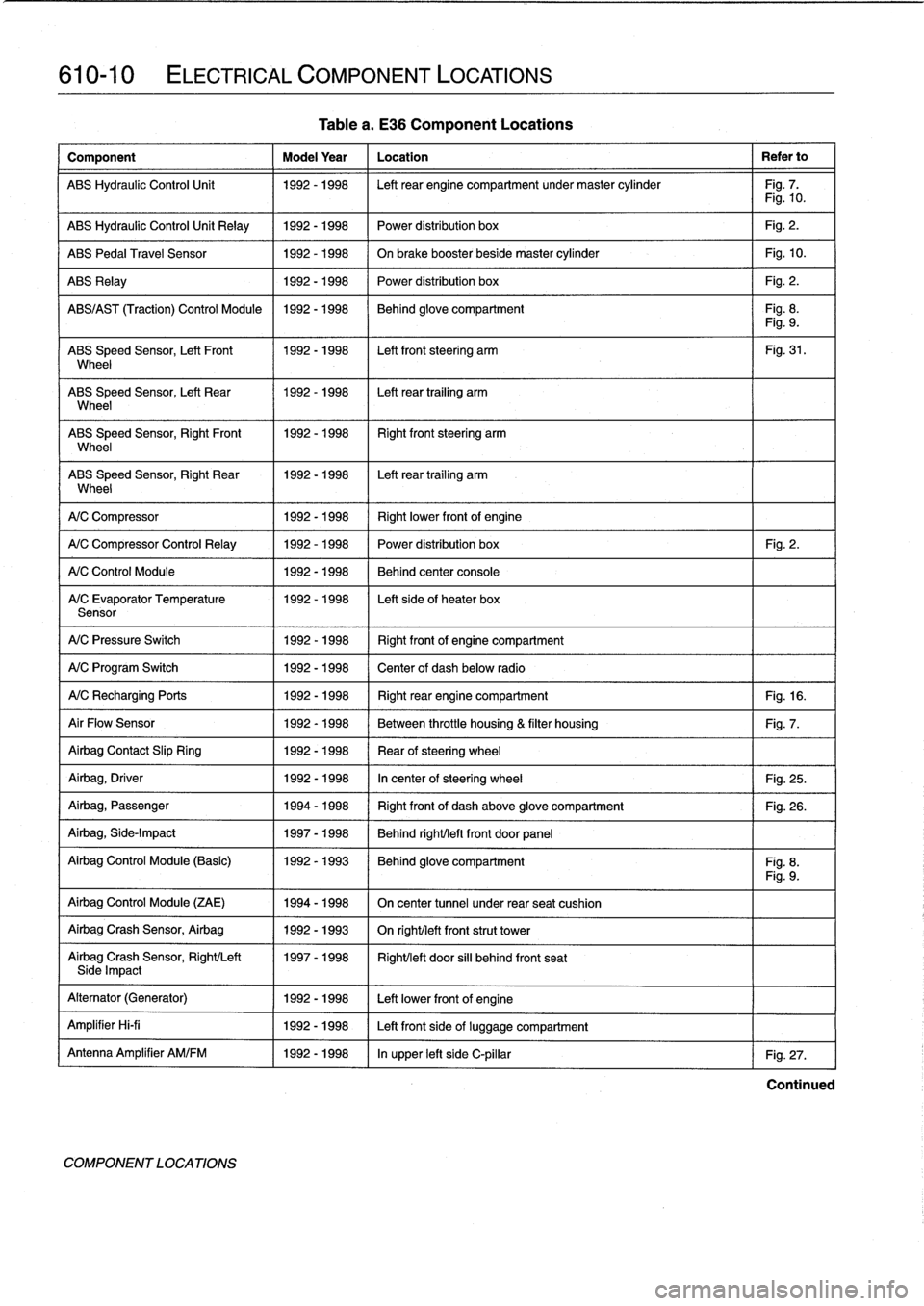
610-10
ELECTRICAL
COMPONENT
LOCATIONS
Component
Model
Year
Location
Refer
to
ABS
Hydraulic
Control
Unit
1992-1998
Left
rear
engine
compartment
undermaster
cylinder
Fig
.
7
.
Fig
.
10
.
ABS
Hydraulic
Control
Unit
Relay
1992-1998
Power
distribution
box
Fig
.
2
.
ABS
Pedal
Travel
Sensor
1992-1998
On
brake
booster
beside
master
cylinder
Fig
.
10
.
ABS
Relay
1992-1998
Power
distribution
box
Fig
.
2
.
ABS/AS
T
(Traction)
Control
Module
1992-1998
Behind
glove
compartment
Fig
.
8
.
Fig
.
9
.
ABS
Speed
Sensor,
Left
Front
1992-1998
Left
front
steering
arm
Fig
.
31
.
Wheel
ABS
Speed
Sensor,
Left
Rear
1992-1998
Left
rear
trailing
arm
Wheel
ABS
Speed
Sensor,
RightFront
11992-1998
Right
front
steering
arm
Wheel
ABS
Speed
Sensor,
Right
Rear
1992-1998
I
Left
rear
trailing
arm
Wheel
1
A/C
Compressor
1
1992-1998
(
Rightlower
frontof
engine
A/C
Compressor
Control
Relay
1
1992-1998
1992-1998
1992-1998
A/C
Control
Module
A/C
Evaporator
Temperature
Sensor
A/C
Pressure
Switch
1992-1998
Right
frontof
engine
compartment
A/C
Program
Switch
1992-1998
Center
of
dash
below
radio
A/CRecharging
Ports
1992-1998
Right
rear
engine
compartment
Fig
.
16
.
Air
Flow
Sensor
1992-1998
Between
throttle
housing
&
filter
housing
Fig
.
7
.
Airbag
Contact
Slip
Ring
1992-1998
Rear
ofsteering
wheel
Airbag,
Driver
1992-1998
In
center
of
steering
wheel
Fig
.
25
.
Airbag,
Passenger
1994-1998
Right
front
of
dash
above
glove
compartment
Fig
.
26
.
Airbag,
Side-Impact
1997-1998
Behind
right/left
front
door
panel
Airbag
Control
Module
(Basic)
1992-1993
Behind
glove
compartment
Fig
.
8
.
Fig
.
9
.
Airbag
Control
Module
(ZAE)
1994-1998
On
center
tunnel
under
rear
seat
cushion
Airbag
Crash
Sensor,
Airbag
1992-1993
On
righUleft
front
strut
tower
Airbag
Crash
Sensor,
Right/Left
1997-1998
Right/left
door
si¡¡
behind
front
seatSide
Impact
Alternator
(Generator)
1992-1998
Left
lowerfront
of
engine
Amplifier
Hi-fi
1992-1998
Left
front
side
of
luggage
compartment
Antenna
Amplifier
AM/FM
1992-1998
In
upper
left
side
C-pillar
Fig
.
27
.
COMPONENT
LOCA
TIONS
Table
a
.
E36
Component
Locations
Power
distribution
box
Fig
.
2
.
Behind
center
console
Left
sideof
heater
box
Continued
Page 401 of 759

Component
Model
Year
Location
Refer
to
Heater
Recirculation
Flap
Actuator
1992-1998
Below
left
dash
right
side
of
steering
column
HeaterBlowerMotor
Resistor
Pack
1992-1998
Behind
center
of
dashboard
Heater
Regulator
FlapActuator
1997-1998
Right
side
of
heater
box
HeaterValve
Assembly
1992-1998
Left
rear
engine
compartment
HeatingNentilation
Relay
Box
1992-1993
Below
left
side
of
dash
HeatingNentilation
Relay
1994-1998
Left
front
footwell
High
Speed
Cooling
Fan
Relay
1992-1998
Power
distribution
box
Fig
.
2
.
Homs,
Right/Left
1993-1998
Front
of
engine
compartment
Horn
Relay
1992-1998
Power
distribution
box
Fig
.
2
.
Horn
Relay
(Alpine)
1994-1998
Behind
glove
compartment
Fig
.
8
.
Board
Computer/Anti-Theft
Fig
.
9
.
Idle
Speed
Control
Valve
1992-1995
Top
rearof
enginebehind
intake
manifold
(M42
engine)
Fig
.
11
.
Idle
Speed
Control
Valve
1992-1995
Top
left
side
of
engine
(M50
engine)
Idle
Speed
Control
Valve
1993-1996
Below
intake
manifold
(M50/S50US
engine)
Idle
Speed
Control
Valve
1996-1998
On
throttle
housing
(M44
engine)
Fig
.
15
.
Idle
Speed
Control
Valve
1997-1998
Left
front
of
engine
below
intake
manifold
(M52/S52US
engine)
Ignition
Coils
1992-1998
Right
of
engineunder
plastic
cover
(four-cylinder)
Fig
.
7
.
Ignition
Cofs
1992-1998
Top
of
engine
undercover
(six-cylinder)
Fig
.
17
.
Ignition
Switch
1992-1998
Right
sídeofsteering
column
Intake
Air
Resonance
Changeover
1992-1998
Leftrear
of
engine
compartment
Valve(DISA)
Intake
Air
Temperature
Sensor
1992-1995
In
mass
air
flow
sensor
(M42
engine)
Intake
Air
TemperatureSensor
1996-1998
In
top
ofair
filter
housing
(M44
engine)
Fig
.
12
.
Intake
Air
Temperature
Sensor
1992-1998
I
Left
sídeof
engine
in
intake
manifold
(six-cylinder)
-
-
I
Fig
.
13
.
Fig
.
14
.
Kick-Down
Switch
(A/T)
1
1992-1998
1
Left
footwell
Mixing
Actuators
1
1992-1998
1
Heater
box
ELECTRICAL
COMPONENT
LOCATIONS
610-15
Table
a
.
E36
Component
Locations
Knock
Sensors
1
1992-1998
1
Left
side
of
engine
block
Left
Front
Power
Window
Motor
11992-1998
/
Left
front
door
Left
Front
Window
Monitoring
Switch
1
1997-1998
1
Left
front
door
trim
panel
Left
Front
Window
Retraction
Switch
1
1992
-
1993
1
Left
front
door
handle
lock
assembly
Left
Splice
Panel
1
1992-1998
1
Under
left
side
of
dash
at
kick-panel
1
Fig
.
5
.
Main
Fuse
and
Relay
Box
(Power
1992-1998
I
Left
sideof
engine
compartment
Fig
.
2
.
Distribution
Box)
1
I
Mass
Air
Flow
Sensor
1992-1998
I
Left
side
of
engine,
intake
air
duct
Fig
.
7
.1
I
Fig
.
15
.
Continued
COMPONENT
LOCATIONS
Page 404 of 759

610-18
ELECTRICAL
COMPONENT
LOCATIONS
Tablea
.
E36
Component
Locations
Component
Model
Year
Location
Refer
to
Transmission
Control
Module
1992-1998
Right
rear
engine
compartment
behíndpanel
Fig
.
7
.
Transmission
Range
Switch
(Gear
1992-1998
Next
to
gear
shift
lever
in
center
console
Fig
.
29
.
Position/Neutra
l
Safety
Switch)
Transmission
Valve
Unít
1992-1993
In
transmission
oil
pan
Transmission
Valve
Unit
1994-1998
On
left
side
of
transmission
Trunk
Lid
Microswitch
1994-1998
In
trunk
lid
Trunk
Lid
Relay
1994-1998
Behind
glove
compartment
(convertible)
Fig
.
8
.
Fig
.
9
.
Trunk
Light
Switch
1992-1998
Left
underside
of
trunk
lid
TrunkLockMotor
1992-1998
Rear
of
luggage
compartment
UnloaderRelay
1992-1998
Inleft
splice
panel
behind
footwell
speaker
grille
Fig
.
5
.
Variable
Camshaft
Control
Module
1994-1996
I
Rear
right
side
of
engine
compartment
(VANOS)
Variable
Camshaft
Control
(VANOS)
1993-1998
Front
ofcylinder
head
Veh¡cle
Speed
Sensor
1992-1998
On
final
drive
Volume
Air
Flow
Sensor
(M42
1992-1995
Left
side
of
engine
compartment
Fig
.
7
.
Engine)
Washer
Fluid
Leve¡
Sensor
1992-1998
Right
frontof
engine
compartment
Washer
Pump
1992-1998
Right
side
of
engine
compartment
on
windshield
washer
reservoir
Fig
.
7
.
Wiper
Motor
1992-1998
Rear
engine
compartment
Wiper
Motor
Relay
1992-1998
Inleft
splice
panel
behind
footwell
speaker
grill
Fig
.
5
.
Wiper
Relay
1992-1998
(
Behind
glove
compartment
I
Fig
.
8
./
Fig
.
9
.
Wiper/Washer
Module
1992-1993
Left
side
of
footwell
under
foot
rest
(early)
Wiper/Washer
Module
1993
(late)-
Behind
glove
compartment
Fig
.
8
.
1998
1
Fig
.
9
.
ZAE
Airbag
Control
Module
1
1994-1998
1
On
center
tunnel
under
rear
seat
cushion
ZKE
IV
Control
Module
1994-1998
I
Behind
glove
compartment
Fig
.
8
.I
Fig
.
9
.
COMPONENT
LOCATIONS
Page 555 of 759

8727
4
FRONT
_TPOWER
ER_DIS_TR_IBUTION
BOX
FHOTIN
OXYOENSE_NSORRE_LA
_Y
I
I
RUNAND
I
GRN/VIO
16
START
I
X,
DD>
6
I
GRNIV10GRN/VIO
BRNIGRNRED/WHT
BLK
YELBLK
BRN/ORG
I
U
E
1185-T86
13D
18,
6A
4Y
BY
6Y
2Y
-
,T,
F
E37017
IL
I
L-
I
--!
!
NORMAL
PRESSURE
SPEEDRELAY
SWITCH
G
ELECTRICAL
WIRING
DIAGRAMS
ELE-71
Engine
Management
19921
.8L
(2
of
2)
INTEGRATED
CLIMATE
HEATEDOXYGEN
CRANKSHAFT
CAMSHAFT
REGULATION
SENSOR
POSITION/RPM
POSITION
CONTROLMODULE
SENSOR
SENSOR
I
I
a
<
I
X181
.58
1
X
18185
UV
U
~
22
2
2
2
F
',-
~
F
~
_
_
_
_
vvvv
I
-
tt
i
2
I
I
I
1
I
1
__
r
-
I
.I
r
-
-
I
I
I
1
BLKIWHT
2
"
~~{I
VEHICLE
SPEED
GRN
I
1
1
1
zlzl
1
1
zl
1
1
1
.
.1
1
I
X17
(
OUTPUT
WHT/BLK
21
I
FUEL
%ifi
(CONSUMPTION
BRN/BL
/BL
CYL(-2
CYL3-4
ENGINECOOLANT
KNOCK
KNOCK
TEMPERATURESENSOR
SENSOR
SENSOR
>I
BLK
20
'EN
.IMEBPEE
.
1
INPUT
I
II
SERVICE
II
REMINDER
I
I
INDICATOR
I
GRG~
~
I
X1fi
I
INSTRUMENT
WlON-BOARD
CLUSTER
COMPUTER
Ks
w-HT/B~~
-
"
BLK~VIO
lI
I
i
ON-BOARD
COMPUTER
BLKIVIO
81
r
I
CIOBCOMP
I
WHT/BLK
17
LK/WHT
T3CIFCINPUT
I
B
{IVSOUTPUT
I
ORY
IENGINDICAT0R
I
BLK
74
,
1ESINPUT
I
VIOIGRV
B6
IICRCMOD
I
Y
EL
SLK
1B
I
CAM
SENS
SIG
B
44,
I
CAM8ETURN
BLK
BB
CPS
SIG
yEL
"'
BLK/
I
CPS
RETURN
PRESSSWITCH
-
B
I
BRN/B
ICYLI-2KS
(SHIELD--------
BRN/RED
78
ICYL3-4
K5
IECTSENS
GRYIWHTB
59~ITPSINPUT
ITPSSENSOR
G
I,VAFSENSOR
GRY/YEL
41
(
_
IVAFSENSOR
GRY/SLU
14
~
I
INTEMP
SENS
GRYRYIV
~INTEMPSENS
GRYIVIO
4
GRY/BLU
6
GRY/WHT
1
GRYIYEL
2
GRY/BLK
3
GRY/WHT
1
SRN
2
BRN/BLK
3
ENGINECONTROL
MODULE
(OME)
VOLUMEAIR
FLOW
SENSOR
THROTTLE
POSITION
SENSOR
Page 557 of 759

8727
6
GRN/VIO
BRNIGRN
RED/WHT
RED/WH
T
RED/WHTRED/WHT
REDRED
W/EGS
FRONT
POWER
DISTRIBUTION
BOX
I
OXYGENSENSOR
RELAY
I
HEATED
OXYGEN
CAMSHAFT
CRANKSHAFT
SENSOR
POSITION
POSITION/
SENSORRPMSENSOR
1S)
X199]9
ELECTRICAL
WIRING
DIAGRAMS
ELE-73
Engine
Management
19922
.511-
(2
of
2)
86
v
30
v
87
I
_
W
[~~j
O
TRANSMISSIONS
SYSTEM
----------
---------
--------
-------
TRANSMISSIONTRANSMISSION
TRANSMISSION
CONTROL
AUTOMATIC
TRANSMISSION
MODULE
(EGS)
RANGE
SW
ITCH
HOT
IN
RUNAND
START
(FRONT
FUSE
pOYfER
I
F28
I
DISTRIBUTION
I
-AJBOX
6Y
X]4
017
INTAKEAIR
THROTTLE
ENGINECOOLANT
TEMPERATURE
POSITION
TEMPERATURE
SENSORSENSORSENSOR
O
j
1I
20j1Sj18~
10
DATA
LINK
CONNECTOR
YEL
70
I
ON-BOARD
BLK/VIO
81
1023
GROUNDCOMPUTER
4
ION-BCOMP
A/C
L~
VIO/GRY
86!
I
SYSTEM
IICRCRTLMOD
NOTUSED
HOTINRUNANOSTART
F"~
;/~
FRONT
4/F2SE
POWER
I
F7
(DISTRIBUTION
L~
-
JBOX
INSTRUMENT
23X7
.6
CLUSTER
~/
/
/p~
\
\
/
CHECK
f
\di/
ENGINE
I
BLK/WHT
GRV/BLU
B
GRV/WHT
6
GRV/YEL
1
BLK/WHT
73
r
IVSS
GRY
8
~
ED7a
ISRVCREMINO
BRN/
~JECTSENS
BRN
3
~IGROUND
BR"/81K
12
~1TPSINPUT
RED
/V
EL
59~
ISVREF
DR
IIATSENS
YEL
67
ICRNKSHFTSENS
BL
I
CRNKSHFTSENSBRN
/
RG
28
~
I
GROUND
EL
ICAMSHFTSENS
-
ICAMSHFTSENS
BL
0251G
71,
BLK/BLU
48,
I
IA/C
COMPCTRL
WHT/BLK
17
BRNI
G
R
LCONS
NIG
JV
64
~
ITRAN
CTRL
MOD
BRN/ORG
11,
I
DKV
GRV/BLU
41
-j
'
-~
.AFMETER
I
BLKKIG~y
88
IPRESSSWITCH
I
END
NE
CONTROL
MODULE
(OME)
NOFMALSPEEDRELAY
BLKBLK/GRV
z
N~I
I
I
PRESSURE
S
W
ITCH
(-__----
MASS
AIR
FLOWSENSOR
Page 559 of 759

8727
8
GR
FUEL
PUMP
FRONT
POWER
DISTRIBUTION
BOX
-
-
-
-
-
-
----
-
-
-
-
-
-
I
H
OTIN
OXYGENSENSOR
RELAY
I
HEATEDOXYOEN
I
RUNAND
SENSOR
VII
O
I
k
I
FUSE
I
F18
I
1sA
GRN
EXCEPT
zl¢I
alGBN/~I
31811~
"
BLK
20
ENGINESPEED
--\
INPUT
WHTIBLK
21
FUEL
GIN/VIO
I
mI
QGRN
VIO
BRNGRNRED
WHT
ml
flED/WHTflED/WHT
LT
6117
I
DRY
~~
W1EGS
I
W/EGS
L
IENGINDICATOR
BLK
BLK
.
ELK
74
7
ELK
16
ICRANKRPHI
ICAMPOSSENS
ELK
VEL
44
I
CAMPOS
SENS
WH7/BLK
_
WHT/BLK
17I
FUELCONSSIG
68
87
2Y
GRN
Engine
Management
1993-951
.8L
(2
of
2)
a
ELECTRICAL
WIRING
DIAGRAMS
ELE-75
I
ELK
,
ICRANKSENS
YEL67i
ICRANKSENS
B
R
N/
ORG
28
,I
SHEILO
GROUND
_____SRN
36
I;
EEVALVECTRL
WHT/YEL
2B,
L
ISCVALVECTRL
,ED/W
.I
199531811
m
819930NLY
INTEGRATED
CLIMATE
CRANKSHAFT
CAMSHAFT
REGULATION
POSITION/RPM
POSITION
CON7ROLM000LE
SENSOR
SENSOR
I
~~BRNIBL
gRNIBLCA
INSTRUMENT
CLUSTER
SYSTEM
11995,
EXCEPT
-U)
2,J
1
J
.
1
.l
2A,
A,
I,
i
l
_
I
I
I
I
L__i
EL
LT
VAPORATIVE
IDLESPEED
INTAKEAIR
NORMAL
EMISSION
CONTROL
RESONANCE
SPE
EDR
PRESSURE
CVLl-2
CYL3-4
ENGINECOOLANT
VALVEVALVE
CHANGEOVER
SWITCH
KNOCKKNOCK
TEMPERATURE
VALVE
9930NLY)
(1
9
953
1
BlI811
SENSOR
SENSOR
SENSOR
81
ANTI-
THEFT
SYSTEM
(31811
ONLY)
(CONSUMPTION
I
GR
~
CHECK
ENGINE
I
BATTERY
BRNN/BU
f
"
-
IARCVALVE
BLKIG
RR
e5
(
i
K
15
I
AIC
PRESS
I
CYL
l-2
KS
BRN/BLK
4ISENSGROUND
~ICVL3-4KS
BRNIFEI
78
IENOCOOLTEMP
BR
N
12,;THROTTLEPOS
GRY/WHT
5
9,
I5VSUPPLY
GRVIBLK~
I
VAF
SENSOR
GRY/VEL
<1,
I
VAFSENSOR
GRY
RY/BI
VAFSENSOR
I
GRV/VID
77
{
,
VAFSENSOR
I
GRY
I
VIO
4
GRV/BLU
5
GRY/WHT
1
GRYIYEL
2
GRYISL
GRYIWHT
t
BRN
2
BRNIBLK
3
ENG
ME
CONTROL
MODULE
(OME)
VOLUMEAIR
FLOW
SENSOR
jT
;RT~dl
-
8,
THROTTLE
POSITION
SENSOR