Page 1313 of 1333

Fig. 2: Identifying Front Wiper Relay Terminals (Montero)
Courtesy of Mitsubishi Motor Sales of America.
Intermittent Operation Check (Montero)
1) Connect battery voltage to terminal No. 1 and ground
terminal No. 6. See Fig. 2. Connect a jumper wire with test light
between battery positive and terminal No. 2.
2) Connect one end of a jumper wire to terminal No. 3 and
touch the other end to negative terminal on battery. Test light should
illuminate briefly and then go out after terminal No. 3 is touched to
battery ground.
FRONT WIPER SWITCH
NOTE: Front wiper switch is located on steering column.
See STEERING COLUMN SWITCHES article in the
ACCESSORIES/SAFETY EQUIP Section.
REAR WIPER MOTOR
Operation Check (Montero)
Disconnect wiring connector from wiper motor. Connect battery
voltage to one terminal and ground to other terminal to ensure
automatic operation. See REAR WIPER MOTOR OPERATION CHECK table for
terminal numbers and model application. See Fig. 3.
REAR WIPER MOTOR OPERATION CHECK TABLE
������������������\
������������������\
������������������\
������������������\
������������������\
������������������\
������������������\
�������������
Model Ground Pin No. Apply Voltage To Pin Nos.
Montero ................. 3 .................................... 1
������������������\
������������������\
������������������\
������������������\
������������������\
������������������\
������������������\
�������������
Page 1314 of 1333
Fig. 3: Identifying Rear Wiper Motor Terminals (Montero)
Courtesy of Mitsubishi Motor Sales of America.
Automatic Stop Check (Montero)
1) Start motor operation by connecting battery voltage to one
terminal and grounding another terminal. See
REAR WIPER MOTOR OPERATION CHECK table. See Fig. 3. Disconnect wires
during operation to stop motor in mid-sweep.
2) Jumper terminals No. 2 and 3 together. Connect battery
voltage to remaining terminal and ground wiper motor bracket. Ensure
motor parks wiper arm.
REAR WIPER RELAY
Operation Check (Montero)
Relay is located to right of heater blower assembly. Leave
intermittent relay connected to wiring harness. Operate rear wiper and
check voltage at terminal No. 1. See Fig. 4. There should be 12 volts
when rear wiper stops. Zero volts should be present when rear wiper is
operating.
Fig. 4: Identifying Rear Wiper Relay Terminals
Courtesy of Mitsubishi Motor Sales of America.
REAR WIPER SWITCH
Page 1318 of 1333
Fig. 1: Identifying Tie-Off Symbols
4) If the wires are not drawn all the way to another
component (across several pages), a reference will tell you their
final destination.
5) Again, use the legend on the first page of the wiring
diagram to determine the grid number and letter of the referenced
component. You can then turn directly to it without tracing wires
across several pages.
6) The symbols shown in Fig. 1 are called tie-offs. The first
tie-off shown indicates that the circuit goes to the temperature
sensor, and is also a ground circuit.
7) The second symbol indicates that the circuit goes to a
battery positive parallel circuit. The third symbol leads to a
particular component and the location is also given.
8) The lines shown in Fig. 2 are called options. Which path
or option to take depends on what engine or systems the vehicle has.
Page 1325 of 1333

WIR IN G D IA G RAM S
�
1991 M it s u bis h i M onte ro
1991 Wiring Diagrams
Mitsubishi
Montero
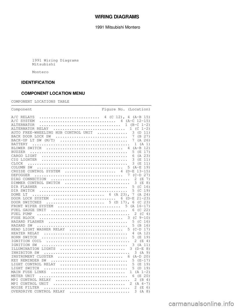
IDENTIFICATION
COMPONENT LOCATION MENU
COMPONENT LOCATIONS TABLE������������������\
������������������\
������������������\
������������������\
������������������\
������������������\
�����������
Component Figure No. (Location)
A/C RELAYS .......................... 4 (C 12), 4 (A-B 15)
A/C SYSTEM ................................. 4 (A-C 12-15)
ALTERNATOR ................................... 1 (B-C 1-2)
ALTERNATOR RELAY ............................... 1 (C 1-2)
AUTO FREE-WHEELING HUB CONTROL UNIT ............. 3 (D 11)
BACK DOOR LOCK SW ............................... 7 (B 27)
BACK-UP LT SW (M/T) ............................. 7 (A 26)
BATTERY .......................................... 1 (A 1)
BLOWER SWITCH ................................. 4 (A-B 12)
BUZZER .......................................... 5 (E 17)
CARGO LIGHT ..................................... 6 (A 23)
CIG LIGHTER ..................................... 3 (E 11)
CLOCK ........................................... 3 (E 11)
COLUMN SW ..................................... 5 (A-E 19)
CRUISE CONTROL SYSTEM ...................... 4 (D-E 13-15)
DEFOGGER ...................................... 7 (C-D 27)
DIAG CONNECTION .................................. 2 (E 7)
DIMMER CONTROL SWITCH ............................ 3 (E 8)
DIR FLASHER ..................................... 5 (C 16)
DIR SWITCH ...................................... 5 (C 19)
DOME LT ............................... 6 (A 23), 7 (A 24)
DOOR LOCK SYSTEM ........................... 6 (D-E 21-23)
DOOR SWITCHES ......................... 5 (D 17), 6 (C 23)
FRONT WIPER SYSTEM ........................... 5 (A 16-17)
FUEL GAUGE UNIT ................................. 6 (C 22)
FUEL PUMP ........................................ 2 (C 4)
FUSE BLOCK .................................... 3 (C 9-10)
HAZARD FLASHER .................................. 5 (C 16)
HAZARD SW ....................................... 5 (B 16)
HEAD LIGHT WASHER RELAY ....................... 5 (C-D 17)
HEATER RELAY .................................... 4 (A 12)
HORN SWITCH ..................................... 5 (E 19)
IGNITION COIL .................................... 2 (E 4)
IGNITION SW ..................................... 3 (A 11)
ILLUMINATION LIGHTS ............................ 3 (D-E 8)
INHIBITOR SW ..................................... 3 (A 9)
INSTRUMENT CLUSTER ............................ 6 (A-D 20)
KEY REMINDER SW ................................. 5 (E-17)
LIGHT CONTROL RELAY ............................. 5 (E 19)
LIGHT SWITCH .................................... 5 (D 19)
MAIN FUSE LINKS ................................ 1 (A 1-2)
METER UNIT ...................................... 6 (E 20)
MPI CONTROL RELAY ................................ 2 (B 4)
MPI CONTROL UNIT ............................... 2 (A 4-7)
NOISE FILTER ..................................... 2 (E 6)
OVERDRIVE CONTROL RELAY .......................... 3 (A 8)