Page 29 of 1216

INTRODUCTION AND MASTER TROUBLESHOOTING - Mast& Tro6blerhootbia
MASTER TROUBLESHOOTING7 *
I,._ ,...
r. ENGINE OVERHEATSi ”
SymptomEngine overheatsProbable causeCooling system faulty
Incorrect ignition timingReference page: I._),7-5
8-169
ENGINE WILL NOT CRANK OR CRANKS SLOWLY
SymptomEngine will not crank
or cranks slowlyProbable causeStarting system faulty
,’
Reference page8-153
ENGINE WILL NOT START OR
HbRD TO START (CRANKS OK)
SymptomProbable causeReference page
Engine will not start or hard toNo fuel supply to injector
-start (Cranks OK)
Injection system problems
-Ignition system problems
8-16!$/ ”;Vacuum leaks11-5..“,:’l Purge control valve hose25-4
l Vacuum hoses
l Intake manifoldl Air intake plenum
l Throttle body
l EGR valveCompression too low
g-23,‘, :. ” ‘,;A;ROUGH IDLE OR ENGINE STALL
Symptom
Rough idle or engine stallsProbable cause
Vacuum leaks
l Purge control valve hosel Vacuum hosesl Intake manifoldl Air intake plenuml Throttle bodyl EGR valve
“. ._
Reference page or remedy
11-525-4
Ignition system problems
Idle speed set too low8-169Check idle speed control sys-
tem
Idle mixture too lean or too rich
Fuel injection system problems
Exhaust gas recirculation
(EGR) system
problems
Engine overheatsCompression too low
-
-
25-l 57-5
9-23
Page 30 of 1216
30INTRODUCTION AND MASTER TROUBLESHOOTING - Master Troubleshooting
ENGINE HESITATES OR POOR ACCELERATION
SymptomEngine hesitates or poor
accelerationProbable causeIgnition system problem
Vacuum leaks
l Purge control valve hose
l Vacuum hosesl Intake manifoldl Air intake plenum
l Throttle bodyl EGR valveReference page
8-169
11-525-4
Air cleaner clogged
Fuel line clogged
Fuel injection system problem
Emission control system problem
l EGR system always on
Engine overheats
Compression too low
-
-
-25-15
7-5
9-23
ENGINE
DIESELING
SymptomEngine dieseling (runs after
ignition switch is turned off)Probable causeIncorrect ignition timingReference page
8-169
EXCESSIVE OIL CONSUMPTION
Symptom
Excessive oil consumptionProbable cause
Oil leak
Positive crankcase ventilation line clogged.
Valve stem seal worn or damaged.Valve stem worn.
Piston ring worn or damaged.Reference page or remedy
Repair as necessary.25-7
g-55.114
g-55.114
g-66,128
Page 303 of 1216

-
ENGINE - Specifications9-19Items
Oil sprocketpump
Silent shaft sprocket
Timing belt tensioner nut or bolt
Timing belt rear cover (upper)
(lower)
Oil drivenpump gear
Front case
Connecting rod bearing cap
Crankshaft bearingcap
<2.0L DOHC Engine>
Engine mount bracket to bracket nut or bolt
Engine cooler pipe to engine front case
Exhaust pipe to exhaust manifold (Turbo)
Oil return pipe to oil pan (Turbo)
Oil screen nut or bolt
Centermember installation bolt
Oil pipe to engine (Turbo)
Rocker cover
Center cover
Heat protector to exhaust manifold
Exhaust manifold to turbocharger(Turbo)
Intake manifold stay bolt
Cylinder head bolt
Crankshaft pulley
Oil sprocketpump
Silent shaft sprocket
Auto tensioner
Timing belt tensioner pulley
Timing belt idle pulley
Timing belt rear cover
Oil drivenpump gear
Front case
Engine oil cooler mounting nut
Eye bolt (Engine oil cooler side)
Engine oil hose mounting bolt
Engine oil feed hose assembly to Feed/Return tube assembly
Engine oil return hose assembly to Feed/Return tube assembly
Feed/Return tube assembly to oil filter bracket
Eye bolt (Oil filter bracket side)
Crankshaft angle sensor
Throttle body stayNm
ft.lbs.
34-4026-29
34-4025-29
22-3016-22
IO-127-9
12-159-11
34-4025-29
15-18
11-1332-3524-25
50-5537-39
17-26
12-19
40-4529-33
40-6029-43
8-106-7
15-2211-16
80-l 0058-72
14-19
10-142.5-3.52-3
2.5-3.52-3
12-15
9-l 155-65
40-47
25-3018-22
90-10065-72
20-3014-22
50-6036-43
43-49
31-35
20-2714-2043-55
31-4034-42
25-30
10-127-9
34-4025-29
20-2214-16
8-126-9
30-3522-25
3-52-4
40-5029-36
40-5029-36
3-52-4
40-4529-33
IO-137-9
15-2211-16SEALANTS AND ADHESIVES
NOSCE-.Items
Specified sealant
“. _
SemiWrcularMOPAR Part No.4318034Rocker cover
<2.0L
1(No.4318034No.1141~1
1 Oil pan1No.MD997110I
Page 368 of 1216
9-84ENGINE <2.0L DOHC Engine> -Camshafts and Camshaft Oil Seals
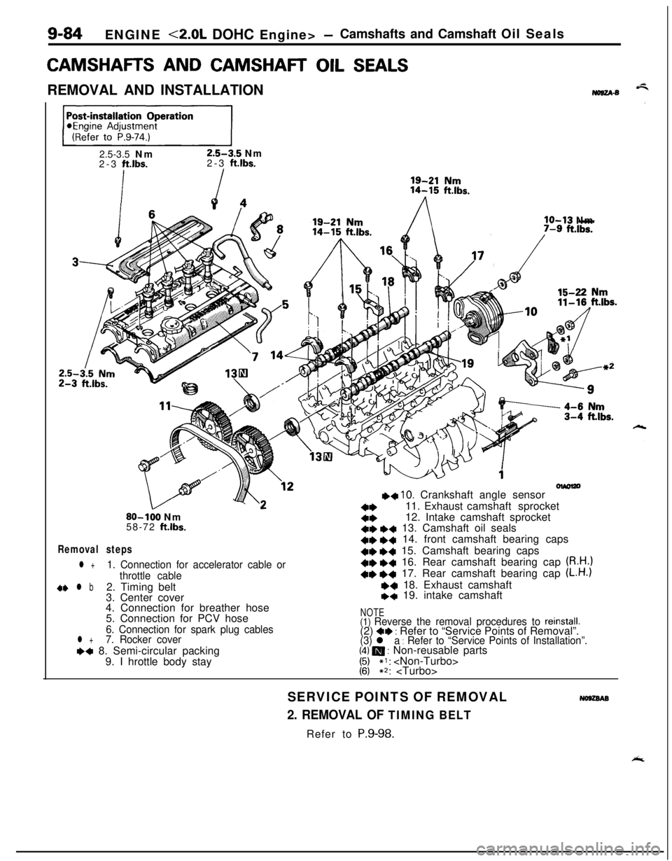
CAMSHAFR AND CAMSHAR OIL SEALSREMOVAL AND INSTALLATION
No8u-s
ppEJ=-j2.5-3.5 Nm
2.5-3.5 Nm
2-3 ft.lbs.2-3 ft.lbs.
lo-13 Nm
olmlzo++ 10. Crankshaft angle sensor
a*11. Exhaust camshaft sprocket80-100 Nm4*12. Intake camshaft sprocket
58-72 ftlbs.+e *+ 13. Camshaft oil seals
Removal steps+e e+ 14. front camshaft bearing caps41)
+4 15. Camshaft bearing caps
l +1. Connection for accelerator cable or+e +c 16. Rear camshaft bearing cap (R.H.)
throttle cable+e +4 17. Rear camshaft bearing cap (L.H.)
d+ l b2. Timing belt~~ 18. Exhaust camshaft
3. Center cover+q 19. intake camshaft
4. Connection for breather hose
5. Connection for PCV hose
NOTE
6. Connection for spark plug cables(1) Reverse the removal procedures to reinstall.(2) 4* : Refer to “Service Points of Removal”.l +7. Rocker cover
(3) l a : Refer to “Service Points of Installation”.~~ 8. Semi-circular packing(4) m : Non-reusable parts
9. I hrottle body stay
1:;*I: ~2:
SERVICE POINTS OF REMOVAL
No9zsAB
2. REMOVAL OF TIMING BELTRefer to P.9-98.
Page 425 of 1216

--
INTAKE AND EXHAUST - SDecificationsII-3
ItemsIntake manifold
<1.8L Engine>
Accelerator cable to air intake plenum
Fuel high pressure hose to delivery pipe
Delivery pipe to intake manifold
Intake manifold stay
Engine hanger
Intake manifold to engine
Throttle body
Air intake plenum stay
Air intake plenum to intake manifold
Water outlet fitting
EGR valveEGR temperature sensor
Ground cable to air intake plenum
Control harness protector to air intake plenum
CoverIntake manifold
<2.0L DOHC Engine>
Accelerator cable to intake manifold
Throttle body stay
Fuel high pressure hose to delivery pipe
Delivery pipe to engine
Intake manifold stay
Intake manifold to engine
Mounting bolt
(M8)Mounting nut and bolt (MIO)
Ignition coil
Power transistor unit
Throttle body
EGR valveEGR temperature sensor
Control harness protector to intake manifold
Control harness clamp bolt
ixhaust manifold
<1.8L Engine>
Front exhaust pipe to exhaust manifold
Front exhaust pipe to engine
Exhaust manifold cover (A) to exhaust manifold
Exhaust manifold cover (B) to exhaust manifold
Exhaust manifold cover (A) to exhaust manifold cover (B)
Exhaust manifold to engine
Oxygen sensor
Engine oil level gauge guide mounting bolt
ixhaust manifold
<2.0L DOHC Engine (Non-Turbo)>
Front exhaust pipe to exhaust manifold
Front exhaust pipe to engine
Heat protector (A), (B)
Exhaust manifold to engine
Oxygen sensor
Engine hanger to engine
ixhaust manifold and turbocharger
<2.0L DOHC Engine (Turbo)>
Front exhaust pipe to exhaust fitting
Front exhaust pipe to engine
Heat protector (A),
(B)
Nmft.lbs.
4-6
3-4
4-6
3-4
IO-137-9
18-25
13-18
15-20II-14
15-2011-14
15-22II-16
15-2011-14
15-2011-14
17-2012-14
IO-157-11
IO-127-9
10-127-9
4-6
3-4
IO-137-9
4-6
3-4
15-22
11-16
4-6
3-4
IO-137-9
25-3018-22
15-2011-14
30-4222-30
20-2714-20
IO-127-9
15-22
11-16
15-22II-16
IO-127-9
4-6
3-4
IO-127-9
30-4022-29
30-4022-29
27-33
20-24
20-2814-20
8-106-7
15-2011-14
40-5029-36
12-15
9-l 1
30-4022-29
30-4022-29
12-15
9-l 1
25-3018-22
40-5029-36
12-15
9-l 1
40-6029-43
30-4022-29
12-15
9-11
Page 436 of 1216
II-14INTAKE AND EXHAUST -Intake Manifold < 1.8L Engine>
/15-20 Nm
11-14
ft.lbs.
lo-13 Nm
18167-9 ft.lbs.15-20 Nm11-14
ft.lbs.I/15-20 Nm
I26IO-15 Nm7-11
ftm’bs.
-17-20 Nm
12-14 ft.lbs.15-20 Nm
Removal steps05AO180
+* l a 16. Delivery pipe, fuel injector and pressureregulator17.Insulator
18.Insulator19. Intake manifold stay20.Engine hanger
2 1.Thermostat housing22.Intake manifold23. Intake manifold gasket24. Throttle body assembly25.Gasket26. Air intake plenum stay
27. Air intake plenum
28. Air intake plenum gasket
lb+ 29. Cover 30. Gasket 31. EGR valve 32. EGR gasket
33. EGR temperature sensor 34. Water outlet fitting35. Gasket36. Thermostat
NOTE(1) Reverse the removal procedures to reinstall.
(2) a* : Refer to “Service Points of Removal”.
(3) l * : Refer to “Service Points of Installation”
(4) q : Non-reusable parts
Page 439 of 1216
INTAKE AND EXHAUST - Intake Manifold <2.0L DOHC Engine>I I-1.7INTAKE MANIFOLD
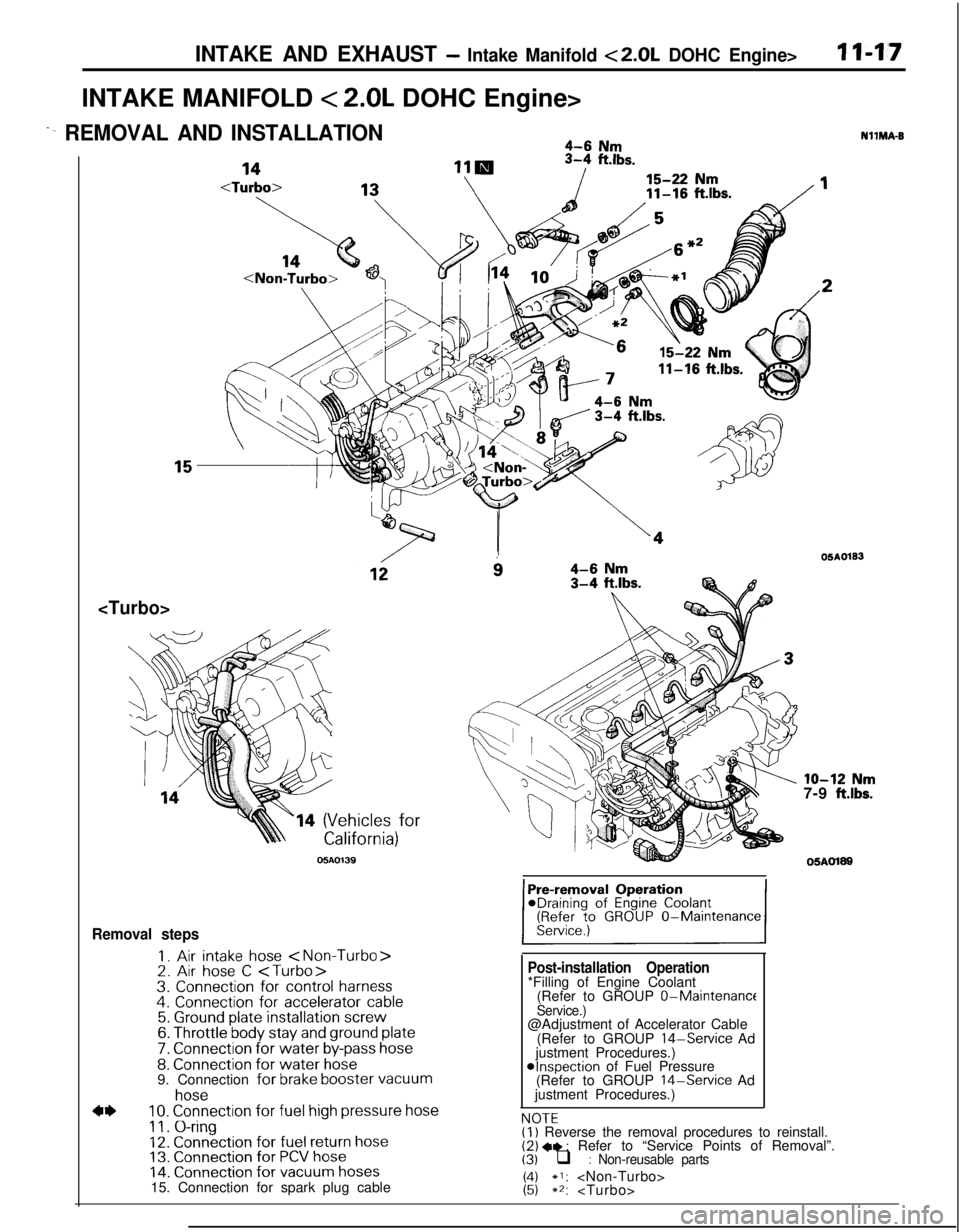
< 2.0L DOHC Engine>
^- REMOVAL AND INSTALLATION4-6 Nm
11-16
ft.lbs.
14 (Vehicles for
05AO139
i34-6 Nm3-4 ftlbs.
Removal steps
I. Air intake hose 2. Air hose C 3. Connection for control harness4. Connection for accelerator cable5. Ground plate installation screw6. Throttle body stay and ground plate
7. Connection for water by-pass hose8. Connection for water hose9. Connection for brake booster vacuum
4*
hose10. Connection for fuel high pressure hose
11. O-ring12. Connection for fuel return hose13. Connection for PCV hose14. Connection for vacuum hoses15. Connection for spark plug cable
Post-installation Operation*Filling of Engine Coolant
(Refer to GROUP 0-Maintenance
Service.)@Adjustment of Accelerator Cable
(Refer to GROUP
14-Service Ad
justment Procedures.)
@Inspection of Fuel Pressure
(Refer to GROUP 14-Service Ad
justment Procedures.)
NOTFNllMA-B
OSAO133
lo-12 Nm7-9 ft.lbs.
05AOl89
,.-.-(I) Reverse the removal procedures to reinstall.(2) +e : Refer to “Service Points of Removal”.(3) q : Non-reusable parts
1:;*I: **:
Page 440 of 1216
11-18INTAKE AND EXHAUST - Intake Manifold < 2.0L DOHC Engine>
10-27 Nm14-20 ft.lbs.
18hIO-13 Nm
7-9
ft.lbs.15-22 Nm11-16
ft.lbs.IO-12 Nm
7-9
ftlbs.05A0197
15-22 Nm
11-16
ftlbs.
wi2” vlo-12 Nm
7-9 ftlbs.25-30 Nm
18-22
ft.lbs.
24
\‘27
28lll
Removal steps
+e l + 16. Delivery pipe, fuel injector and pressureregulator17. Insulator18. Insulator19. Intake manifold stay
20. Intake manifold21. Intake manifold gasket22. Ignition coil23. Power transistor unit24. EGR valve25. Gasket26. EGR temperature sensor 27. Air fitting 28. Gasket 05A0196
29. Connection for control harness
30. Throttle body31. Gasket
NOTE(I) Reverse the removal procedures to reinstall.(2) l * : Refer to “Service Points of Removal”.(3) l + : Refer to “Service Points of Installation”.(4) 0 : Non-reusable parts


