Page 548 of 1216

14-94FUEL SYSTEM - Fuel Tank
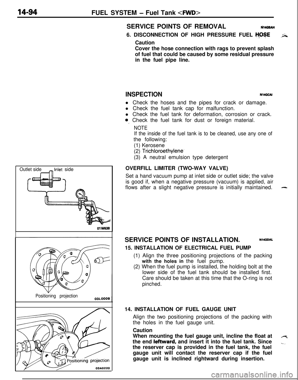
Outlet side_ Inlet side01
W838
Positioning projection
03A0220SERVICE POINTS OF REMOVALtilirro8AH
6. DISCONNECTION OF HIGH PRESSURE FUEL
H;OSECaution
Cover the hose connection with rags to prevent splash
of fuel that could be caused by some residual pressure
in the fuel pipe line.
INSPECTIONN14GCAll Check the hoses and the pipes for crack or damage.
l Check the fuel tank cap for malfunction.
l Check the fuel tank for deformation, corrosion or crack.
0,. Check the fuel tank for dust or foreign material.
NOTE
If the inside of the fuel tank is to be cleaned, use any one ofthe following:
(1) Kerosene
(2)
Trichloroethylene-(3) A neutral emulsion type detergent
OVERFILL LIMITER (TWO-WAY VALVE)
Set a hand vacuum pump at inlet side or outlet side; the valve
is good if, when a negative pressure (vacuum) is applied, air
flows after a slight negative pressure is initially maintained.
SERVICE POINTS OF INSTALLATION.
Nl4DDAL15. INSTALLATION OF ELECTRICAL FUEL PUMP
(1) Align the three positioning projections of the packing
with the holes in the fuel pump.
(2) When the fuel pump is installed, the holding bolt at the
lower side of the fuel tank should be installed first.
Care should be taken at this time that the O-ring is not
pinched.14. INSTALLATION OF FUEL GAUGE UNIT
Align the two positioning projections of the packing with
the holes in the fuel gauge unit.
Caution
When mounting the fuel gauge unit, incline the float at
the end leftward, and insert it into the fuel tank. Since
the reserver cap is provided in the fuel tank, the fuel
gauge unit will contact the reserver cap if the fuel
gauge unit is inclined rightward during insertion.
-
4
-,
Page 552 of 1216

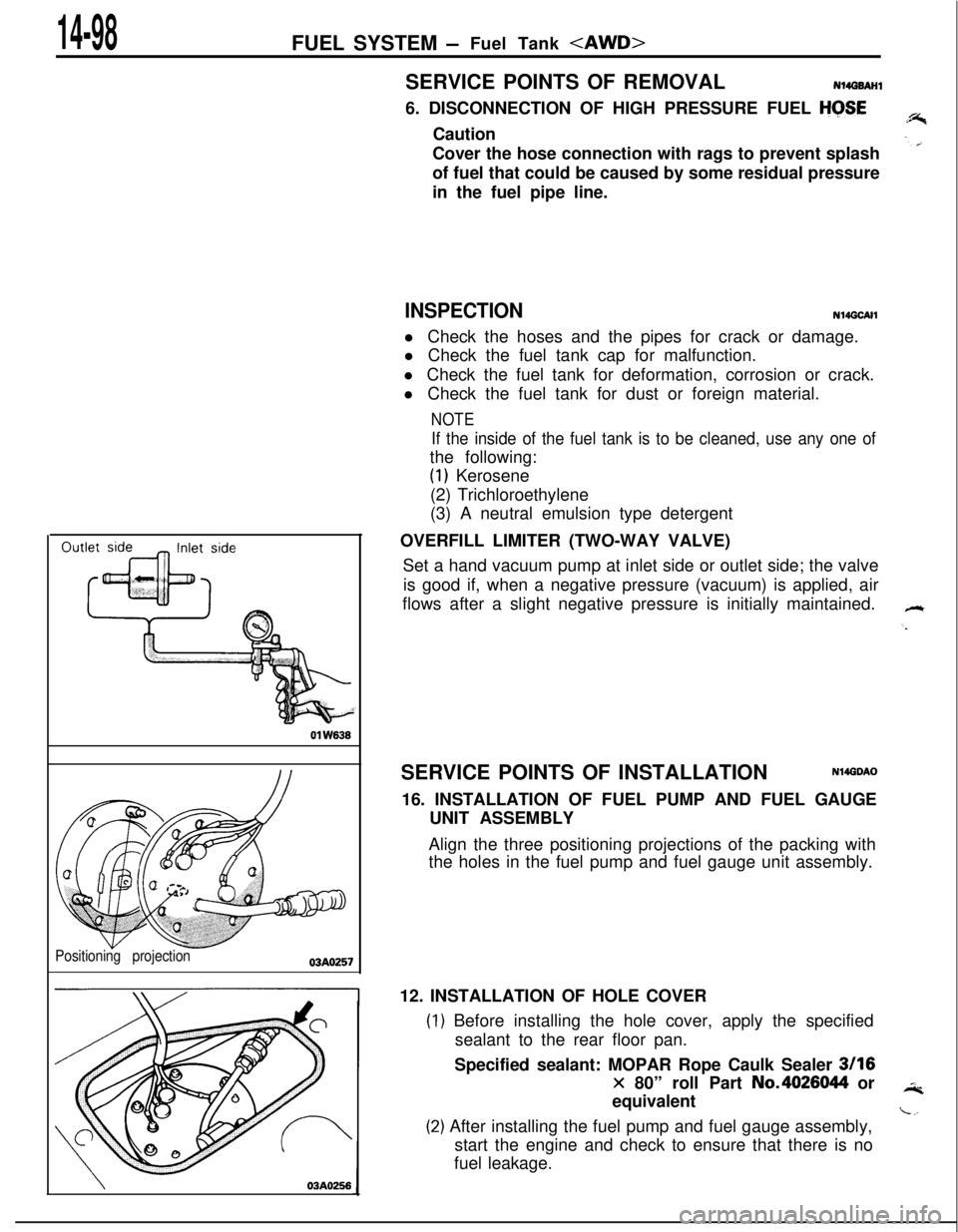
14-98FUEL SYSTEM -Fuel Tank 01
W636
Positioning projection03AO257
\03A0256SERVICE POINTS OF REMOVAL
N14G6AHl6. DISCONNECTION OF HIGH PRESSURE FUEL
HGSECaution
Cover the hose connection with rags to prevent splash
of fuel that could be caused by some residual pressure
in the fuel pipe line.
INSPECTIONN14GCAHl Check the hoses and the pipes for crack or damage.
l Check the fuel tank cap for malfunction.
l Check the fuel tank for deformation, corrosion or crack.
l Check the fuel tank for dust or foreign material.
NOTE
If the inside of the fuel tank is to be cleaned, use any one ofthe following:
(1) Kerosene
(2) Trichloroethylene
(3) A neutral emulsion type detergent
OVERFILL LIMITER (TWO-WAY VALVE)
Set a hand vacuum pump at inlet side or outlet side; the valve
is good if, when a negative pressure (vacuum) is applied, air
flows after a slight negative pressure is initially maintained.
SERVICE POINTS OF INSTALLATION
N14GDAO16. INSTALLATION OF FUEL PUMP AND FUEL GAUGE
UNIT ASSEMBLY
Align the three positioning projections of the packing with
the holes in the fuel pump and fuel gauge unit assembly.
12. INSTALLATION OF HOLE COVER
) Before installing the hole cover, apply the specified
sealant to the rear floor pan.
Specified sealant: MOPAR Rope Caulk Sealer
3116
x 80” roll Part No.4026044 or
equivalent
!) After installing the fuel pump and fuel gauge assembly,
start the engine and check to ensure that there is no
fuel leakage.
Page 1216 of 1216

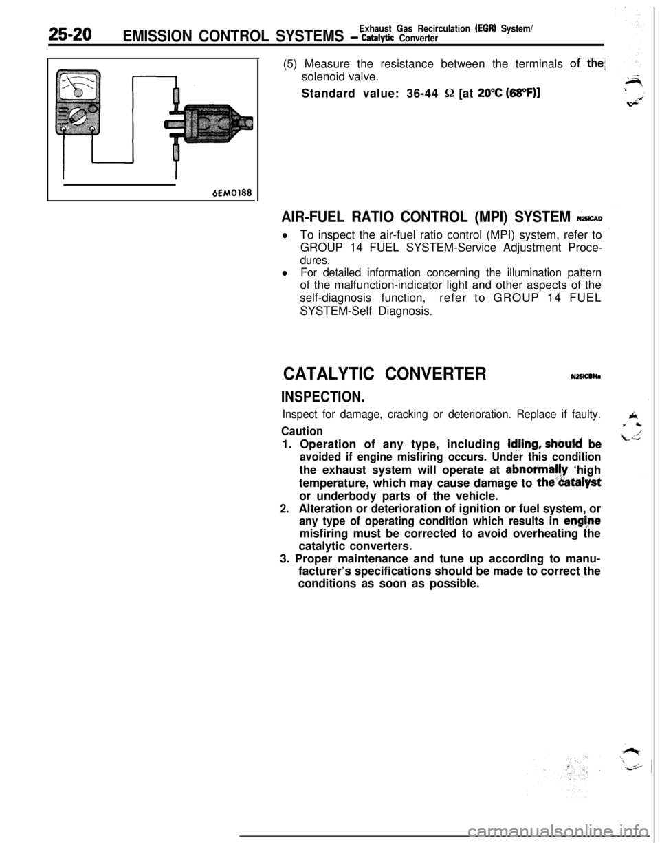
25-20Exhaust Gas Recirculation (EGR) System/EMISSION CONTROL SYSTEMS - ‘catalytic Converter(5) Measure the resistance between the terminals
of- the
Standard value: 36-44
Q [at 20°C (68OF)l
6EM0188
AIR-FUEL RATIO CONTROL (MPI) SYSTEM &CAD
lTo inspect the air-fuel ratio control (MPI) system, refer to
GROUP 14 FUEL SYSTEM-Service Adjustment Proce-
dures.
lFor detailed information concerning the illumination patternof the malfunction-indicator light and other aspects of the
self-diagnosis function,refer to GROUP 14 FUEL
SYSTEM-Self Diagnosis.
CATALYTIC CONVERTERN25lCBHa
INSPECTION.
Inspect for damage, cracking or deterioration. Replace if faulty.
Caution1. Operation of any type, including
idjing, should be
avoided if engine misfiring occurs. Under this conditionthe exhaust system will operate at abnormally ‘high
temperature, which may cause damage to
the”Catalystor underbody parts of the vehicle.
2.Alteration or deterioration of ignition or fuel system, or
any type of operating condition which results in enghtemisfiring must be corrected to avoid overheating the
catalytic converters.
3. Proper maintenance and tune up according to manu-
facturer’s specifications should be made to correct the
conditions as soon as possible.