Page 957 of 1216

AUTOMATR: TRANSAXLE - Transaxle Assemblv 21-263
SERVICE POINTS OF REMOVALNZlL8AU14. DISCONNECTION OF
TIE ROD END/15 LOWER ARM
BALL JOINT
Refer to
P.21-227.16. REMOVAL OF DRIVE SHAFT
(R.H.)/ 17. DRIVE SHAFT
(L.H.) Refer to
P.21-227.16. REMOVAL OF DRIVE SHAFT (R.H.)
(1) Use the suitable tool to push out the drive shaft (R.H.]from the front hub.
I1 lA0288(2) Insert a pry bar at the projection part and remove the
drive shaft
(R.H.) from the transaxle.
Caution
Do not pull out the drive shaft; doing so will
damage the T.J.; be sure to use the pry bar.
17. DISCONNECTION OF DRIVE SHAFT (L.H.)
(1) Take out the drive shaft by lightly tapping the drive shaftT.J. case with a plastic hammer.
NOTERemove the drive shaft with the hub and knuckle, etc.,
as an assembly.
Caution
1. Removing the drive shaft from the outboard
joint side can cause damage to the inboard joint.Always use a plastic hammer, etc., to remove
the drive shaft.
2. Tapping on the center bearing can damage it.
Never tap on the bearing.
(2) Keep the removed drive shaft as far away from the
transaxle case as possible, and secure (by using rope,
etc.) the joints to the body so that it does not fall.
18. REMOVAL OF FRONT EXHAUST PIPE
Refer to GROUP 1 l-Exhaust Pipe and Main Muffler.
Page 990 of 1216
21-296 AUTOMATIC TRANSAXLE - Transaxle Assembly 76. Put the oil temperature sensor in the case.
77. Install an O-ring in the O-ring groove on top of the valve
body assembly.
78. Replace the solenoid valve harness grommet O-ring with anew O-ring.
79. Pass the solenoid valve connector through from the inside
of the transaxle case hole.
80. Insert the solenoid valve harness grommet in the case hole.,**%4
81. Temporarily install the valve body while inserting the detentplate pin in the manual valve groove. Then install the oil
temperature sensor and holder and tighten the bolts with
the specified torque.
A bolt
= 18 mm (.71 in.)
B bolt = 25 mm (.98 in.)
C bolt = 40 mm (1.57 in.)
Valve body assembly mounting bolts:
lo-12 Nm (7.5-8.5 fklbs.)
Caution
Fix the solenoid valve and oil temperature sensor
harness securely in the position shown.
82. Install the oil filter.
Oil filter mounting bolts: 5-7 Nm (4-5
ft.lbs.1
Page 992 of 1216

21-298 AUTOMATIC TRANSAXLE - Transaxle Assembly 91. Insert the center shaft and hit it with a plastic hammer or
similar instrument to install it securely
.
NOTEApply ATF to the oil seal lip and do not scratch it.
92. Apply ATF to the oil pump drive hub, install the torque
converter and push it in securely so dimension A shown in
the figure reaches the standard value.
Standard value: Approximately 16.3 mm
(.642 in.)
CAUTIONS DURING COMPONENT DISASSEM-
BLY AND REASSEMBLYGeneral cautions when cleaning
1. Clean each part, blow out oil passages and oil holes, etc.
with air and check that nothing is clogged.
2. For cleaning fluid, use the designated ATF (automatic
transmission fluid) or kerosene.3. When drying parts with air, be careful not to get ATF or
kerosene on your face.Cautions when handling parts
1. After washing the parts, arrange them in order so inspec-
tion, repairs and assembly can be performed properly.
2. When disassembling the valve body, store each valve,
making a group of the various springs.
3.Soak the new brake and clutch discs used for replacementin ATF for more than 2 hours before assembly.
General cautions during reassembly
1.Be sure to apply ATF to seal rings, clutch disc, clutch plateand rotating parts and sliding parts and then install.
2.Replace all gaskets and O-ring with new ones and do not
reuse the old ones.
3.Use petrolatum to hold the parts in their specified places.
Page 1011 of 1216
AUTOMATIC TRANSAXLEAnnulus Gear and- Transfer Drive Gear Set 44A33.W4A33>21-317
ANNULUS GEAR AND TRANSFER DRIVE GEAR SET
- DISASSEMBLY AND REASSEMBLY
Disassembly steps
l *1. Snap ring2.
Stopperplate
4eI)+ 3. Bearing
l W 4. Bearing
We+ 5. Transferdrive gear
6. Snar, rina
7.
Outbut frange
8. Annulus gear
NOTE(I) Reverse the disassembly procedures to reassemble.(2) +e : Refer to “Service Points of Disassembly”.(3) ++ : Refer to “Service Points of Reassembly”.
TFA0225
SERVICE POINTS OF DISASSEMBLY
3.14. REMOVAL OF BEARINGW5. TRANSFER DRIVE
GEAR(1) Using the special tool, remove the transfer drive gear
and bearings (2) as a set from the output flange.Caution
Install the special tool securely between the outputflange
and bearings.
) Using the special tool, remove the bearings on both
ends of the transfer drive gear.
Page 1021 of 1216
AUTOMATIC TRANSAXLE - Valve Body21-327
SERVICE POINTS OF REASSEMBLY42./33.
LOCATION OF STOPPER PLATES/SO. N-D PLATE/
19. TEFLON BALL/18. STEEL BALL
Install the stopper plates, N-D plate, teflon ball and steel
ball in the upper valve body in the positions shown in the
figure.
17. INSTALLATION OF UPPER VALVE BODY SUB ASSEM-
BLYInstall the special tool, then, after securing the upper
separating plate and the intermediate plate by the eight
installation bolts, remove the special tool.
MD998226
18. INSTALLATION OF OIL FILTER/IS. STEEL BALL/
14. RELIEF SPRINGInstall, to the intermediate plate, the oil filter, the two steel
balls, and the spring.
10. INSTALLATION OF LOWER VALVE BODY SUB ASSEM-
BLY(1) Install the special tool to the intermediate plate.
(2) Install the separating plate.
Page 1022 of 1216
21-328AUTOMATIC TRANSAXLE - Valve Bodv
XSV-ASkV-Brj,,SV (FJA22)TFAM80(3) After securing the lower valve body by
the installationbolt, remove the special tool.
Sk
5./4./3./2. INSTALLATION OF SOLENOID VALVE ASSEM-
BLYInstall each solenoid valve in the position shown in the
figure.
Solenoid valveWiring colorI
Shift control solenoid valve “A”
Shift control solenoid valve “B”
Damper clutch control solenoid valve
Yellow
Red
Pressure control solenoid valveBlue
Page 1102 of 1216

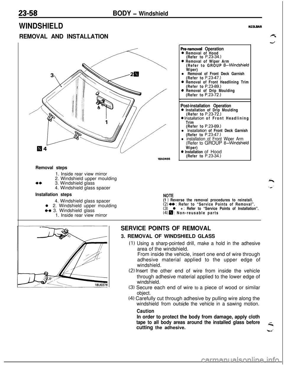
23-58BODY - Windshield
WINDSHIELD
REMOVAL AND INSTALLATION
ISA0466
Pre-removal Operation0 Removal of Hood
(Refer to P.23-34.)0 Removal of Wiper Arm
(Refer to GROUP &WindshieldWiper)
l Removal of Front Deck Garnish
(Refer to
P.23-47.)0 Removal of Front Headlining Trim
(Refer to P.23-89.)0 Removal of Drip Moulding
(Refer to P.23-72.)
Post-installation Operation0 Installation of Drip Moulding
(Refer to P.23-72.)0 Installation of Front Headlining
Trim
(Refer to
P.23-89.)l Installation of Front Deck Garnish
(Refer to
P.23-47.)l installation of Front Wiper Arm(Refer to GROUP 8-WindshieldWiper)
0 Installation of Hood
(Refer to P.23-34.)
NZBLBAR
,
Removal steps1. Inside rear view mirror
2. Windshield upper moulding
a*3. Windshield glass
4. Windshield glass spacer
Installation steps4. Windshield glass spacer
l 2. Windshield upper moulding
+a 3. Windshield glass
1. Inside rear view mirror
NOTE(1 I Reverse the removal procedures to reinstall.(2) +* : Refer to “Service Points of Removal”.(3) l + : Refer to “Service Points of Installation”.(4) H : Non-reusable parts
SERVICE POINTS OF REMOVAL3. REMOVAL OF WINDSHIELD GLASS
(1) Using a sharp-pointed drill, make a hold in the adhesivearea of the windshield.
From inside the vehicle, insert one end of wire through
adhesive material applied to the upper edge of
windshield.
(2) Insert the other end of wire from inside the vehicle
through adhesive material applied to the lower edge of
windshield.
(3) Secure each end of wire to a piece of wood or similar
object.
(4) Carefully cut through adhesive by pulling wire along the
windshield from outsi,de the vehicle in a sawing motion.
Caution
In order to protect the body from damage, apply cloth
tape to all body areas around the installed glass beforecutting the adhesive.
Page 1104 of 1216

23-60BODY - Windshield
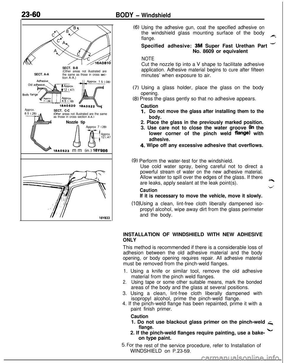
SECT. B-B
SECT. A-A(Other areas not illustrated are
the same as those in cross aec-tion A-A.)
Approx.ISA0520 iSAo522&jSECT. C-C(Other areas not illustrated are the same
as those in cross section A-A.1
Nozzle tip
G QApprox 7
I 28)
Approx12
t.47
1.3~0523 mm (in.) 181988
(6) Using the adhesive gun, coat the specified adhesive onthe windshield glass mounting surface of the body
flange.FiSpecified adhesive:
3M Super Fast Urethan Part -No. 8609 or equivalent
NOTECut the nozzle tip into a
V shape to facilitate adhesive
application. Adhesive material begins to cure after fifteenminutes’ when exposure to air.
(7) Using a glass holder, place the glass on the body
opening.
(8) Press the glass gently so that no adhesive appears.
Caution
1.Do not move the glass after installing them to the
body.
2. Place the glass in the previously marked position.3. Use care not to close the water groove
(in the
lower corner of the pinch weld
flange) with
adhesive.4. Wipe off any excessive adhesive that overflows.
(9) Perform the water-test for the windshield.
Use cold water spray, being careful not to direct a
powerful stream of water on the new adhesive material.Allow water to spill over the edges of the glass. If there
are leaks, apply sealant at the leak point(s).
~
Cautions/
If it is necessary to move the vehicle, move it slowly.
(10)Using a clean, lint-free cloth liberally dampened iso-
propyl alcohol, wipe away dirt from the glass perimeter
and the body.
INSTALLATION OF WINDSHIELD WITH NEW ADHESIVE
ONLYThis method is recommended if there is a considerable loss of
adhesion between the old adhesive material and the body
opening, or body opening requires repair. All adhesive materialmust be removed from the pinch-weld flanges.
1. Using a knife or similar tool, remove the old adhesive
material from the pinch weld flanges.
2.Using tape or some other suitable means, mark the bondedareas of the body and the glass at several positions.
3. Using a clean, lint-free cloth liberally dampened with
isopropyl alcohol, prime the pinch-weld flange.
4. If the pinch-weld flange has been repainted, prime it with a
paint finish primer.
Caution1. Do not use blackout glass primer on the pinch-weld
q
flange.2. If the pinch-weld flanges require painting, use a bake-
Lon type paint.
5. For the rest of the service procedure, refer to Installation of
WINDSHIELD on
P.23-59.