Page 975 of 1146
EXTERIOR - Rear Wiper and Washer
51-3718N007F
jINTERMITTENT WIPER RELAY
(1) Remove the quarter trim. (Refer to GROUP 52A
- Trims.)
(2) With the intermittent wiper relay connected to the wiring
harness connector, let the wiper operate intermittently and
check the voltage at terminal
0.WASHER MOTOR
(1) When the washer motor is inspected, make sure that it is
mounted on the washer tank and that the washer tank is
filled with water.
(2) Connect the battery as shown to check whether water is
pumped out.
SERVICE POINT OF INSTALLATION
2. INSTALLATION OF WIPER ARM
After assembling the wiper blade to the wiper arm, install
the wiper arm with its tip positioned along the ceramic part.
TSB Revision
Page 981 of 1146
L
LINTERIOR
- Troubleshooting52A-3
POWERWINDOWSRELAY
EXFRSWITCH
D-21m,
%
325 6I
11:Iq z/
1: :-I
124
321IEe$l 34--- ----- ---
3ce?Di
b ’
:zs5:5:mcucu;c2&
r!Gt 1 M 2
LUMBAR
SUPPORT
MOTOR
IQ 2 1
SIDESUPPORT
MOTOR1Q2
ROWER SEAT
ASSEMBLY
J/B
2B
I
1C-82 5
f
J;19 C-78I
1 TSB RevisionI1
Page 1016 of 1146
52B-6SUPPLEMENTAL RESTRAINT SYSTEM (SRS) - General Information
;RS SCHEMATIC
STARTER RELAYIGNITION SWITCH MIT
I
‘dIGNITION SWITCH
IMulti
-purpose fuses
Connector
lock switch
----
r
1
UNLOCKiM/T -AA
IWarning light
malfunction
detection circuitICrank signal detection circuit
Connector lock
detection circuit
Safing
impact
sensor
1
N
i-Multi-use ,
Tester
interface
circuit
Self-diagnosis
check connector
(For Multi-use
Tester)
19FO141Front impact
sensor
(L.H.)Clock spring
Front impact
sensor (R.H.)IP-l-Air bag
module
TSB Revision
Page 1083 of 1146

55-1
HEATER, AIR
CONDITIONER
AND VENTILATION
CONTENTSM55AA- -
HEATERS AND AIR CONDITIONING................3HEATER UNIT*........................................................................22
SPECIFICATIONS
....................................................................3REFRIGERANT LINE................................................................35General Specifications
........................................................3RESISTOR................................................................................20Lubricants
............................................................................4SAFETY PRECAUTIONS........................................................9Sealant and Adhesive............................................................4
Service Specifications3SERVICE ADJUSTMENT PROCEDURES............................10........................................................
SPECIAL TOOLS4Charging Procedures............................................................11
i
........................................................................Charging the Refrigerant....................................................12Compressor Drive Belt Adjustment....................................11
HEATERS AND MANUAL AIR CONDITIONER5Compressor Noise................................................................16
................................................16
AIR CONDITIONER SWITCH................................................21Handling Tubing andFittings
Idle-up Operation Check....................................................17
BELT LOCK CONTROLLER20Performance Test................................................................15....................................................
BLOWER ASSEMBLYPower Relay Check............................................................17............................................................23Refrigerant Leak Repair Procedure....................................15COMPRESSOR........................................................................
27TestProcedures....................................................................10
CONDENSER AND CONDENSER FAN MOTOR................33TROUBLESHOOTING............................................................5
ENGINE COOLANT TEMPERATURE SWITCH....................
39VENTILATORS (AIR INLET AND AIR OUTLET)................38
EVAPORATOR
........................................................................
25VENTILATORS (INSTRUMENT PANEL)*............................36
HEATER CONTROL ASSEMBLY*
........................................18CONTINUED ON NEXT PAGE
SUPPLEMENTAL RESTRAINT SYSTEM (SRS)
(1)A Supplemental Restraint System (SRS), which uses a driver-side air bag, has been installed in the 3000GT.(2)The SRS includes the following components: impact sensors, SRS diagnosis unit: SRS warning light, air bagmodule, clock spring, interconnecting wiring. Other SRS-related components (that may have to be
removed/installed in connection with SRS service or maintenance) are indicated in the table of contents byan asterisk (*).
WARNING!(1)Improper service or maintenance of any component of the SRS, or any SRS-related component, can lead to
personal injury or death to service personnel (from inadvertent firing of the air bag) or to the driver (fromrendering the
SRS inoperative).(2) Service or maintenance of any SRS component or SRS-related component must be performed only at anauthorized MITSUBISHI dealer.
(3) MITSUBISHI dealer personnel must thoroughly review this manual, and especially its GROUP 52B
-Supplemental Restraint System (SRS), before beginning any service or maintenance of any component of theSRS or any SRS-related component.
Page 1087 of 1146
HEATERS AND MANUAL AIR CONDITIONER - Troubleshooting55-5
HEATERS AND MANUAL AIR CONDITIONER
t+-/ TROUBLESHOOTING
L
M55ECAE
Symptom
Heater insufficientheatProbable cause
Obstructed heater outlets
Blend air dampers improperly adjusted or binding
Thermostat malfunction
Obstructed heater hoses
Remedy
Correct
Replace
No ventilation evenwhen mode selectionknob is operatedImproperly adjusted control cables
Plugged or partially plugged heater core
Incorrect adjustment of mode selection dampersIncorrect installation of mode selection controlwire
Ducts are incorrectly/incompletely connected,crushed, bent or clogged
Burnt-out fuse
Poor grounding
Malfunction blower switch
Malfunction resistorAdjust
Clean or replace
Adjust
Blower motor
inoperative
Repair or replace
ReplaceCorrect
Replace
Malfunction blower motor
Malfunction heater relay
Malfunction blower motor relay
TSB Revision
Page 1089 of 1146

L
2OFOO85HEATERS AND MANUAL AIR CONDITIONER
- Trqubleshooting55-7
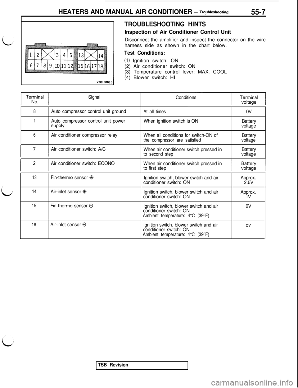
TROUBLESHOOTING HINTSInspection of Air Conditioner Control Unit
Disconnect the amplifier and inspect the connector on the wire
harness side as shown in the chart below.
Test Conditions:
(1) Ignition switch: ON
(2) Air conditioner switch: ON
(3) Temperature control lever: MAX. COOL
(4) Blower switch: HI
1 Terrrnal 1Signal
Conditions
8Auto compressor control unit groundAt all timesov
1Auto compressor control unit power
SUPPlY
When ignition switch is ON
Battery
voltage
6Air conditioner compressor relay
When all conditions for switch-ON of
Battery
the compressor are satisfiedvoltage
I ’I
Air conditioner switch: A/C
When air conditioner switch pressed inBattery
to second stepvoltage
Air conditioner switch: ECONO
When air conditioner switch pressed in
to first step
13Fin-therm0 sensor 0Ignition switch, blower switch and airApprox.
conditioner switch: ON2.5V/
LJ14Air-inlet sensor 0Ignition switch, blower switch and air
conditioner switch: ONApprox.IV
15Fin-therm0 sensor 0Ignition switch, blower switch and air
conditioner switch: ON
Ambient temperature: 4°C (39°F)
OV
18Air-inlet sensor 0Ignition switch, blower switch and air
conditioner switch: ON
Ambient temperature: 4°C (39°F)ov
TSB Revision
Page 1090 of 1146

55-8HEATERS AND MANUAL AIR CONDITIONER - Troubleshooting
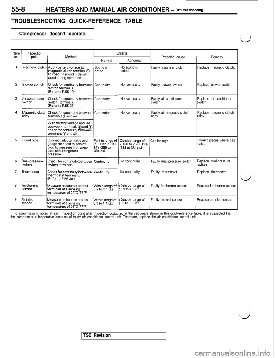
TROUBLESHOOTING QUICK-REFERENCE TABLE
Compressor doesn’t operate.
hen
no.
4
5
6
7
8
9
-
I
I
/
L
switch terminals.
Sensor
”
1
InspectronCriteriapointIMethodProbable causeIRemedy
Abnormal
No sound is
notedFaulty magnetic clutchReplace magnetic clutch.
No continuity
Faulty blower switchReplace blower switch
No continuity
Faulty air conditioner
switchReplace air conditioner
switch.
No continuity
Faulty air magnetic clutch
relayReplace magnetic clutch
relay.
pa;?’ places where gas
II
Vo continuityFaulty dual-pressure switchReplace dual-pressure
\Jo continuityIFaulty thermostatswitch.Replace thermostat.
Outside range of3.9 to 4.1 kfiFaulty fin-therm0 sensorReplace fin-therm0 sensor
3utside range ofFaulty air inlet sensor1.9tol.l kQReplace air inlet sensor.
If no abnormality
is noted at each inspection point after inspection coducted in the sequence shown in this quick-reference table, it is suspected that
the compressor IS Inoperative because of faulty air conditioner control unit. Therefore, replace the air conditioner control unit.
d
d
TSB Revision
Page 1099 of 1146

HEATERS AND MANUAL AIR CbNDlTlONER -Service Adjustment Procedures 55 17
ADJUSTMENT PROCEDURES(1) Select a quiet area for testing. Duplicate conditions as much
as possible. Switch compressor on and off several times to
clearly identify compressor noise.
To duplicate high ambient conditions (high head pressure),
restrict air flow through condenser. Install manifold gauge
set to make sure discharge pressure doesn’t exceed 2,070
kPa (300 psi).
(2) Tighten all compressor mounting bolts, clutch mounting
bolt, and compressor drive belt. Check to assure clutch coil
is tight (no rotation or wobble).
(3) Check refrigerant hoses for rubbing or interference that can
cause unusual noises.
(4) Check refrigerant charge. (See “Charging System”.)
(5) Recheck compressor noise as in Step 1.
(6) If noise still exists, loosen compressor mounting bolts and
retorque. Repeat Step 1.
(7) If noise continues, replace compressor and repeat Step 1.
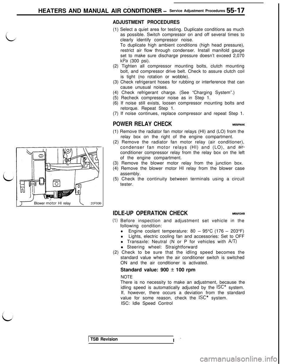
POWER RELAY CHECKMBBFNAK(1) Remove the radiator fan motor relays (HI) and (LO) from the
relay box on the right of the engine compartment.
(2) Remove the radiator fan motor relay (air conditioner),
condenser fan motor relays (HI) and (LO), and
air-conditioner compressor relay from the relay box on the left
of the engine compartment.
(3) Remove the blower motor relay from the junction box.
(4) Remove the blower motor HI relay from the blower case
assembly.
(5) Check the continuity between terminals using a circuit
tester.
J Blower m.otor HI relay\2OFOO6l
IDLE-UP OPERATION CHECKM55FOAB
(1) Before inspection and adjustment set vehicle in the
following condition:
lEngine coolant temperature: 80 - 95°C (176 - 203°F)
lLights, electric cooling fan and accessories: Set to OFF
l Transaxle: Neutral (N or P for vehicles with
A/T)l Steering wheel: Straightforward
(2) Check to be sure that the idling speed becomes the
standard value when the air conditioner switch is switched
ON and the air conditioner is activated.
Standard value: 900
+ 100 rpm
NOTEThere is no necessity to make an adjustment, because the
idling speed is automatically adjusted by the ISC” system.
If, however, there occurs a deviation from the standard
value for some reason, check the ISC” system.
ISC: Idle Speed Control
1 TSB RevisionI -