Page 1 of 4087

ABBREVIATIONS USED IN THIS
MANUAL
ABS Anti±Lock Brake System J/B Junction Block
A/C Air Conditioner LED Light Emitting Diode
ALR Automatic Locking Retractor LH Left±Hand
APPROX. Approximation LHD Left±Hand Drive
A/T, ATM Automatic Transmission LLC Long Life Coolant (Year Around Coolant)
ATF Automatic Transmission Fluid Max. Maximum
BTDC Before Top Dead Center Min. Minimum
BVSV Bimetal Vacuum Switching Valve MP Multipurpose
CALIF. Vehicles Sold in California N Neutral
CB Circuit Breaker OD, O/D Overdrive
DOHC Double Over Head Cam O/S Oversize
DP Dash Pot P & BV Proportioning and Bypass Valve
ECT Electronic Controlled Transmission PCV Positive Crankcase Ventilation
ECU Electronic Controlled Unit PS Power Steering
EFI Electronic Fuel Injection RH Right±Hand
EGR Exhaust Gas Recirculation RL Rear Left
ELR Emergency Locking Retractor RR Rear Right
EPR Evaporator Pressure Regulator RR, Rr Rear
ESA Electronic Spark Advance SRS Supplemental Restraint System
EVAP Evaporative (Emission Control) SSM Special Service Materials
EX Exhaust (manifold, valve) SST Special Service Tools
Ex. Except STD Standard
FIPG Formed in Place Gasket SW Switch
FL Front Left TDC Top Dead Center
FL Fusible Link TDCL Total Diagnostic Communication Link
FPU Fuel Pressure Up Temp. Temperature
FR Front Right TRAC Traction Control System
FR, Fr Front TWC Three±Way Catalyst
HAC High Altitude Compensation VSV Vacuum Switching Valve
IG Ignition VTV Vacuum Transmitting Valve
IN Intake (manifold, valve) w/ With
INT Intermittent w/o Without
ISC Idle Speed Control
IN±34±
INTRODUCTION Abbreviations Used in This Manual
WhereEverybodyKnowsYourName
Page 128 of 4087

������������������\
������������������\
�
������������������\
�����������������
������������������\
������������������\
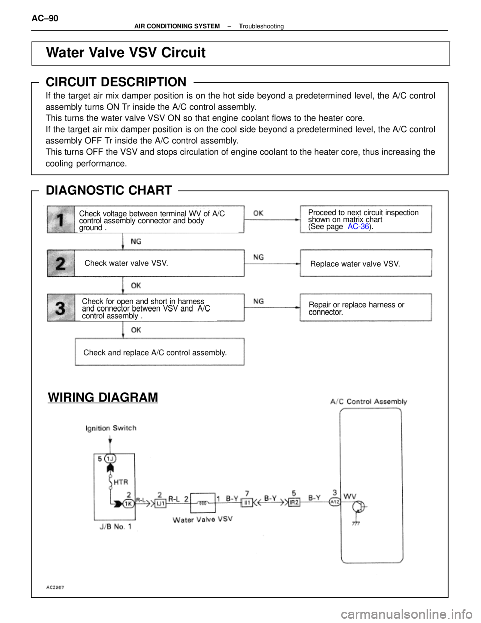
Water Valve VSV Circuit
CIRCUIT DESCRIPTION
If the target air mix damper position is on the hot side beyond a predeter\
mined level, the A/C control
assembly turns ON Tr inside the A/C control assembly.
This turns the water valve VSV ON so that engine coolant flows to the he\
ater core.
If the target air mix damper position is on the cool side beyond a prede\
termined level, the A/C control
assembly OFF Tr inside the A/C control assembly.
This turns OFF the VSV and stops circulation of engine coolant to the he\
ater core, thus increasing the
cooling performance.
DIAGNOSTIC CHART
Check voltage between terminal WV of A/C
control assembly connector and body
ground .
Check water valve VSV.
Check for open and short in harness
and connector between VSV and A/C
control assembly .
Check and replace A/C control assembly.
Replace water valve VSV.
Repair or replace harness or
connector.
Proceed to next circuit inspection
shown on matrix chart
(See page
AC-36).
WIRING DIAGRAM
AC±90±
AIR CONDITIONING SYSTEM Troubleshooting
WhereEverybodyKnowsYourName
Page 129 of 4087

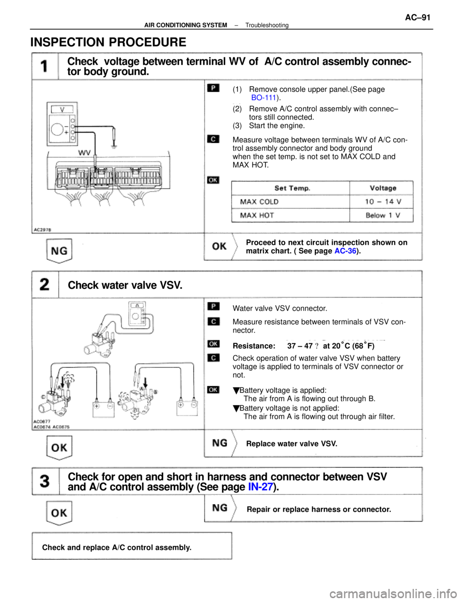
Check voltage between terminal WV of A/C control assembly connec-
tor body ground.
(1) Remove console upper panel.(See page
BO-111).
(2) Remove A/C control assembly with connec±
tors still connected.
(3) Start the engine.
Measure voltage between terminals WV of A/C con-
trol assembly connector and body ground
when the set temp. is not set to MAX COLD and
MAX HOT.
Proceed to next circuit inspection shown on
matrix chart. ( See page AC-36).
Check water valve VSV.
Water valve VSV connector.
Measure resistance between terminals of VSV con-
nector.
Resistance: 37 ± 47 � at 20°C (68°F)
Check operation of water valve VSV when battery
voltage is applied to terminals of VSV connector or
not.
� Battery voltage is applied:
The air from A is flowing out through B.
� Battery voltage is not applied:
The air from A is flowing out through air filter.
Replace water valve VSV.
Check for open and short in harness and connector between VSV
and A/C control assembly (See page IN-27).
Repair or replace harness or connector.
Check and replace A/C control assembly.
INSPECTION PROCEDURE
±
AIR CONDITIONING SYSTEM TroubleshootingAC±91
WhereEverybodyKnowsYourName
Page 164 of 4087
WATER VALVE
REMOVAL OF WATER VALVE
1. DISCONNECT FOLLOWING PARTS FROM WATERVA LV E
wWater hose
w acuum hose
w Connector
2. REMOVE WATER VALVE (a) Remove the two bolts.
(b) Loosen the hose band, then pull off the water hose.
INSPECTION OF WATER VALVE VSV
See page AC±90
±
AIR CONDITIONING SYSTEM Water ValveAC±127
WhereEverybodyKnowsYourName
Page 1291 of 4087
10. REMOVE LH ENGINE WIRE COVERRemove the two bolts and engine wire cover.
11. REMOVE VSV FOR EVAP SYSTEM Remove the two bolts, and disconnect the VSV from cylinder
head and timing belt cover.
12. REMOVE RH NO.3 TIMING BELT COVER Remove the three bolts and timing belt cover.
13. REMOVE LH NO.3 TIMING BELT COVER (a) Remove the four mounting bolts.
(b) Disconnect the cord grommet from the timing belt cover,
and remove the timing belt cover.
(c) Remove the cord grommet from the high±tension cord.
14. DISCONNECT RADIATOR HOSE FROM WATER INLET
15. REMOVE DRIVE BELT IDLER PULLEY Remove the pulley bolt, cover plate and idler pulley.
±
COOLIING SYSTEM Electronically Controlled Hydraulic
Cooling Fan (Hydraulic Pump)CO±29
WhereEverybodyKnowsYourName
Page 1305 of 4087

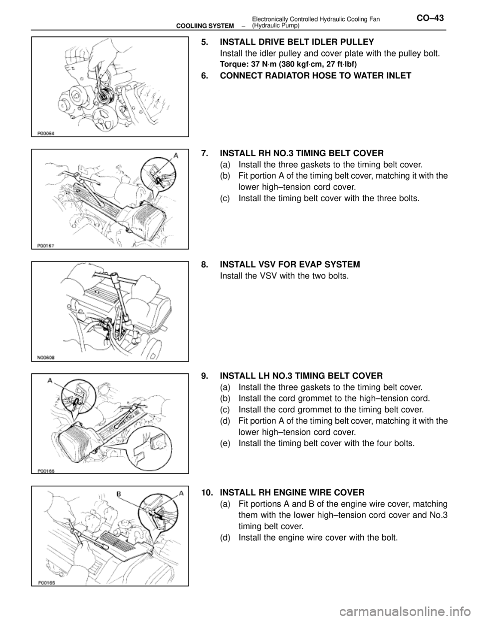
5. INSTALL DRIVE BELT IDLER PULLEYInstall the idler pulley and cover plate with the pulley bolt.
Torque: 37 N Vm (380 kgf Vcm, 27 ft Vlbf)
6. CONNECT RADIATOR HOSE TO WATER INLET
7. INSTALL RH NO.3 TIMING BELT COVER
(a) Install the three gaskets to the timing belt cover.
(b) Fit portion A of the timing belt cover, matching it with the
lower high±tension cord cover.
(c) Install the timing belt cover with the three bolts.
8. INSTALL VSV FOR EVAP SYSTEM Install the VSV with the two bolts.
9. INSTALL LH NO.3 TIMING BELT COVER (a) Install the three gaskets to the timing belt cover.
(b) Install the cord grommet to the high±tension cord.
(c) Install the cord grommet to the timing belt cover.
(d) Fit portion A of the timing belt cover, matching it with the
lower high±tension cord cover.
(e) Install the timing belt cover with the four bolts.
10. INSTALL RH ENGINE WIRE COVER (a) Fit portions A and B of the engine wire cover, matchingthem with the lower high±tension cord cover and No.3
timing belt cover.
(d) Install the engine wire cover with the bolt.
±
COOLIING SYSTEM Electronically Controlled Hydraulic Cooling Fan
(Hydraulic Pump)CO±43
WhereEverybodyKnowsYourName
Page 1306 of 4087

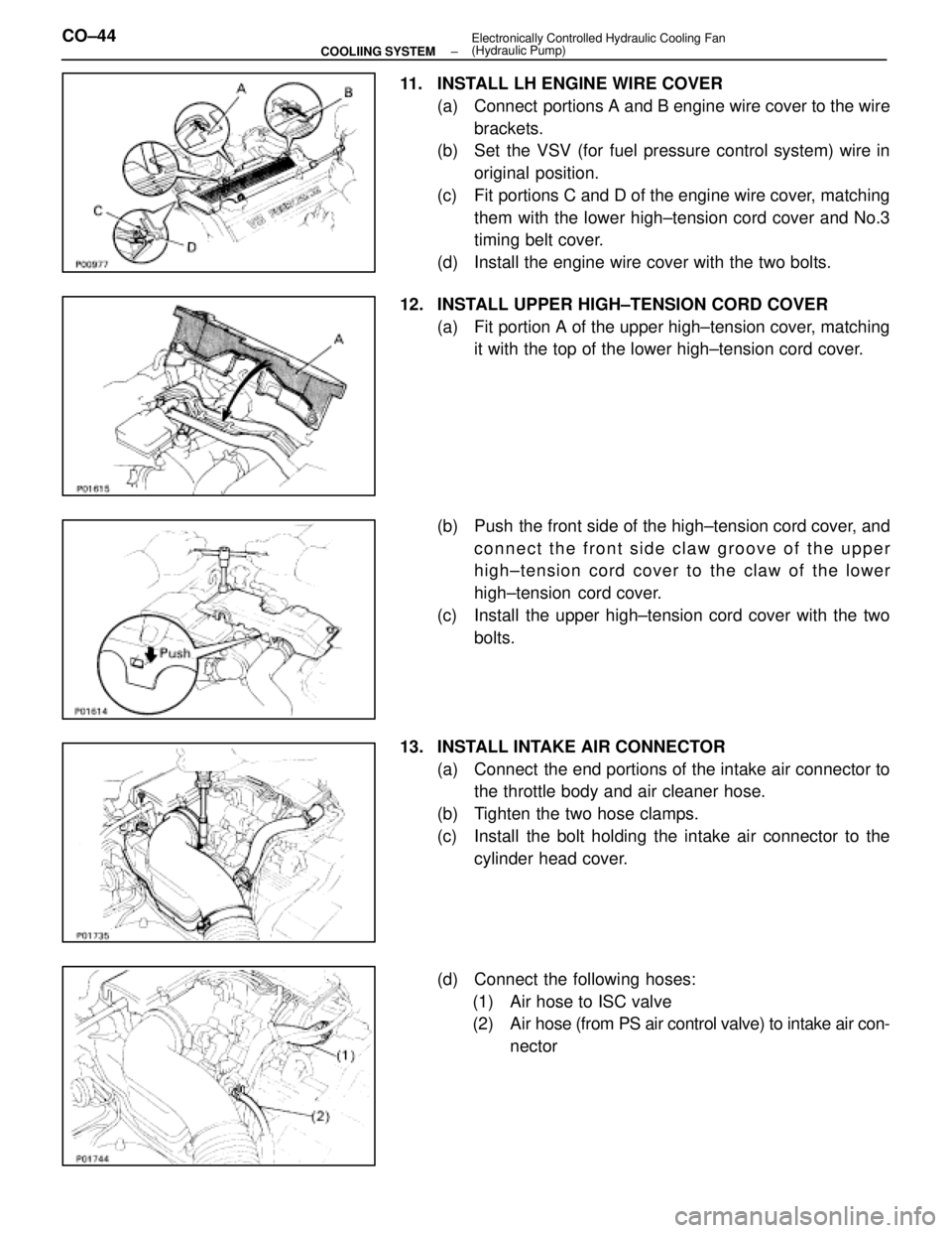
11. INSTALL LH ENGINE WIRE COVER(a) Connect portions A and B engine wire cover to the wirebrackets.
(b) Set the VSV (for fuel pressure control system) wire in
original position.
(c) Fit portions C and D of the engine wire cover, matching them with the lower high±tension cord cover and No.3
timing belt cover.
(d) Install the engine wire cover with the two bolts.
12. INSTALL UPPER HIGH±TENSION CORD COVER (a) Fit portion A of the upper high±tension cover, matchingit with the top of the lower high±tension cord cover.
(b) Push the front side of the high±tension cord cover, and connect the front side claw groove of the upper
high±tension cord cover to the claw of the lower
high±tension cord cover.
(c) Install the upper high±tension cord cover with the two bolts.
13. INSTALL INTAKE AIR CONNECTOR (a) Connect the end portions of the intake air connector tothe throttle body and air cleaner hose.
(b) Tighten the two hose clamps.
(c) Install the bolt holding the intake air connector to the cylinder head cover.
(d) Connect the following hoses: (1) Air hose to ISC valve
(2) Air hose (from PS air control valve) to intake air con- nector
CO±44
±
COOLIING SYSTEM Electronically Controlled Hydraulic Cooling Fan
(Hydraulic Pump)
WhereEverybodyKnowsYourName
Page 1326 of 4087
SERVICE SPECIFICATIONS
SPECIFICATIONS
VSV (For EVAP) Resistance30±34 �
VSV (For EGR)Resistance33±39 �
TORQUE SPECIFICATIONS
Part tightenedN mkgf cmftVlbf
VSV for EGR X Intake manifold18185 13
EGR valve X Intake manifold18185 13
EGR valve X EGR Pipe64650 47
Catalytic converter (Front) X Exhaust manifold62630 46
Catalytic converter (Front) X Front Exhaust pipe43440 32
Front exhaust pipe X Center exhaust pipe43440 32
Sub±oxygen sensor X Front exhaust pipe1818013
EC±20±
EMISSION CONTROL SYSTEMS Service Specifications
WhereEverybodyKnowsYourName