Page 2479 of 4087
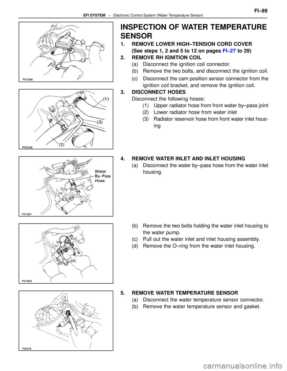
INSPECTION OF WATER TEMPERATURE
SENSOR
1. REMOVE LOWER HIGH±TENSION CORD COVER(See steps 1, 2 and 5 to 12 on pages FI±27 to 29)
2. REMOVE RH IGNITION COIL (a) Disconnect the ignition coil connector.
(b) Remove the two bolts, and disconnect the ignition coil.
(c) Disconnect the cam position sensor connector from the
ignition coil bracket, and remove the ignition coil.
3. DISCONNECT HOSES Disconnect the following hoses:(1) Upper radiator hose from front water by±pass joint
(2) Lower radiator hose from water inlet
(3) Radiator reservoir hose from front water inlet hous-
ing
4. REMOVE WATER INLET AND INLET HOUSING (a) Disconnect the water by±pass hose from the water inlethousing.
(b) Remove the two bolts holding the water inlet housing to the water pump.
(c) Pull out the water inlet and inlet housing assembly.
(d) Remove the O±ring from the water inlet housing.
5. REMOVE WATER TEMPERATURE SENSOR (a) Disconnect the water temperature sensor connector.
(b) Remove the water temperature sensor and gasket. FI±99
EFI SYSTEM
± Electronic Control System (Water Temperature Sensor)
WhereEverybodyKnowsYourName
Page 2480 of 4087
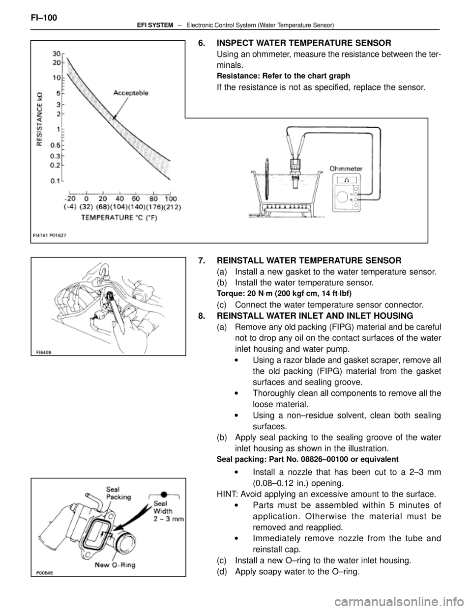
6. INSPECT WATER TEMPERATURE SENSORUsing an ohmmeter, measure the resistance between the ter-
minals.
Resistance: Refer to the chart graph
If the resistance is not as specified, replace the sensor.
7. REINSTALL WATER TEMPERATURE SENSOR (a) Install a new gasket to the water temperature sensor.
(b) Install the water temperature sensor.
Torque: 20 N Vm (200 kgf Vcm, 14 ft Vlbf)
(c) Connect the water temperature sensor connector.
8. REINSTALL WATER INLET AND INLET HOUSING (a) Remove any old packing (FIPG) material and be carefulnot to drop any oil on the contact surfaces of the water
inlet housing and water pump.
w Using a razor blade and gasket scraper, remove all
the old packing (FIPG) material from the gasket
surfaces and sealing groove.
w Thoroughly clean all components to remove all the
loose material.
w Using a non±residue solvent, clean both sealing
surfaces.
(b) Apply seal packing to the sealing groove of the water
inlet housing as shown in the illustration.
Seal packing: Part No. 08826±00100 or equivalent
w Install a nozzle that has been cut to a 2±3 mm
(0.08±0.12 in.) opening.
HINT: Avoid applying an excessive amount to the surface.
w Parts must be assembled within 5 minutes of
application. Otherwise the material must be
removed and reapplied.
w Immediately remove nozzle from the tube and
reinstall cap.
(c) Install a new O±ring to the water inlet housing.
(d) Apply soapy water to the O±ring.
FI±100
EFI SYSTEM
± Electronic Control System (Water Temperature Sensor)
WhereEverybodyKnowsYourName
Page 2481 of 4087
(e) Push in the water inlet housing end into the water pumphole.
(f) Install the water inlet and inlet housing assembly with
the two bolts. Alternately tighten the bolts.
Torque: 18 N Vm (185 kgf Vcm, 13 ft Vlbf)
(g) Connect the water by±pass hose to the water inlet
housing.
9. RECONNECT HOSES Connect the following hoses:(1) Upper radiator hose to front water by±pass joint
(2) Lower radiator hose to water inlet
(3) Radiator reservoir hose to front water inlet housing
10. REINSTALL RH IGNITION COIL (a) Install the ignition coil with the two bolts.
(b) Install the cam position sensor connector to the ignitioncoil bracket.
(c) Connect the ignition coil connector.
11. REINSTALL LOWER HIGH±TENSION CORD COVER (See steps 1 to 13 and 16 to 18 on pages FI±39 to 41)FI±101
EFI SYSTEM
± Electronic Control System (Water Temperature Sensor)
WhereEverybodyKnowsYourName
Page 2516 of 4087
Fuel Cut RPM
INSPECTION OF FUEL CUT RPM
1. WARM UP ENGINEAllow the engine to warm up to normal operating
temperature.
2. CONNECT TACHOMETER Connect the test probe of a tachometer to terminal IG of the
check connector.
NOTICE
w Never allow the tachometer terminal to touch ground as
it could result in damage to the igniter and/or ignition
coil.
w As some tachometers are not compatible with this
ignition system, we recommend that you confirm the
compatibility of yours before use.
3. INSPECT FUEL CUT OPERATION
(a) Increase the engine speed to at least 2,500 rpm.
(b) Check for injector operating noise.
(c) Check that when the throttle lever is released, injectoroperation noise stops momentarily and then resumes.
HINT:
w The vehicle should be stopped.
w Measure with the A/C OFF.
Fuel return rpm: 1,400 rpm
4. REMOVE TACHOMETER
FI±136
± Electronic Control System (Fuel \
Cut RPM)EFI SYSTEM
WhereEverybodyKnowsYourName
Page 2524 of 4087
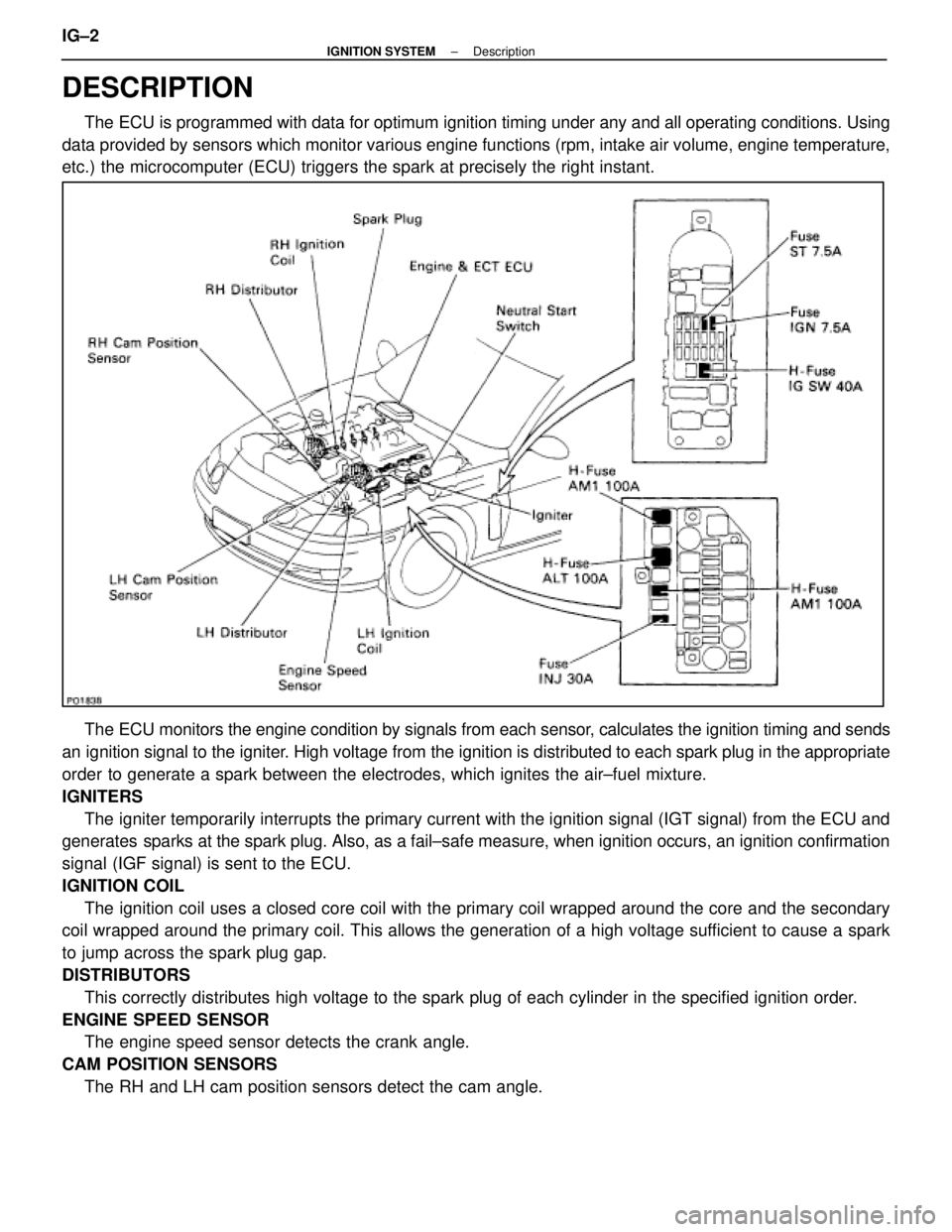
DESCRIPTION
The ECU is programmed with data for optimum ignition timing under any and a\
ll operating conditions. Using
data provided by sensors which monitor various engine functions (rpm, i\
ntake air volume, engine temperature,
etc.) the microcomputer (ECU) triggers the spark at precisely the right ins\
tant.
The ECU monitors the engine condition by signals from each sensor, calculates the ignition timing and sends
an ignition signal to the igniter. High voltage from the ignition is distributed to each spark plug in th\
e appropriate
order to generate a spark between the electrodes, which ignites the air±fu\
el mixture.
IGNITERS The igniter temporarily interrupts the primary current with the ignition si\
gnal (IGT signal) from the ECU and
generates sparks at the spark plug. Also, as a fail±safe measure, when ignitio\
n occurs, an ignition confirmation
signal (IGF signal) is sent to the ECU.
IGNITION COIL
The ignition coil uses a closed core coil with the primary coil wrapped \
around the core and the secondary
coil wrapped around the primary coil. This allows the generation of a hi\
gh voltage sufficient to cause a spark
to jump across the spark plug gap.
DISTRIBUTORS
This correctly distributes high voltage to the spark plug of each cylind\
er in the specified ignition order.
ENGINE SPEED SENSOR The engine speed sensor detects the crank angle.
CAM POSITION SENSORS The RH and LH cam position sensors detect the cam angle.
IG±2
±
IGNITION SYSTEM Description
WhereEverybodyKnowsYourName
Page 2525 of 4087
PRECAUTIONS
1. Do not leave the ignition switch on for more than 10minutes if the engine will not start.
2. With a tachometer connected to the system, connect the tester probe of the tachometer to terminal IG
of the
check (ºDIAGNOSISº) connector.
HINT:
wAllow the engine to warm up to normal operation
temperature.
w Set the tachometer to the 4±cylinder range.
3. As some tachometers are not compatible with this ignition system, we recommend that you confirm the
compatibility of your unit before use.
4. Never allow the tachometer terminal to touch ground as this could damage the igniter and/or ignition coil.
5. Do not disconnect the battery when the engine is running.
6. Check that the igniter is properly grounded to the body.
±
IGNITION SYSTEM PrecautionsIG±3
WhereEverybodyKnowsYourName
Page 2636 of 4087
OKNG
OKNG
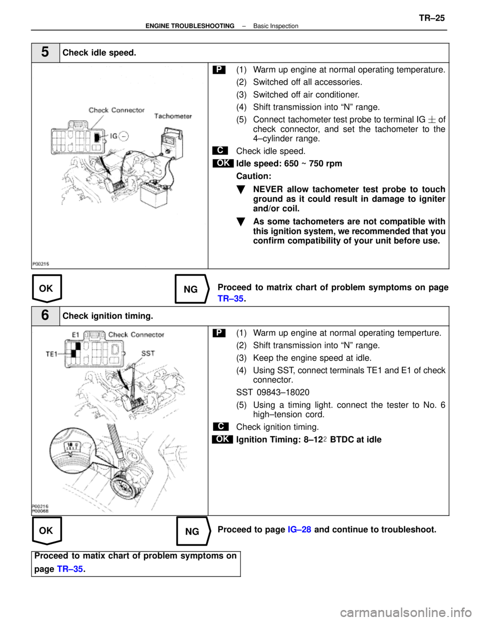
5Check idle speed.
C
OK
P(1) Warm up engine at normal operating temperature.
(2) Switched off all accessories.
(3) Switched off air conditioner.
(4) Shift transmission into ªNº range.
(5) Connect tachometer test probe to terminal IG � of
check connector, and set the tachometer to the
4±cylinder range.
Check idle speed.
Idle speed: 650 ~ 750 rpm
Caution:
�NEVER allow tachometer test probe to touch
ground as it could result in damage to igniter
and/or coil.
�As some tachometers are not compatible with
this ignition system, we recommended that you
confirm compatibility of your unit before use.
Proceed to matrix chart of problem symptoms on page
TR±35 .
6Check ignition timing.
C
OK
P(1) Warm up engine at normal operating temperture.
(2) Shift transmission into ªNº range.
(3) Keep the engine speed at idle.
(4) Using SST, connect terminals TE1 and E1 of check
connector.
SST 09843±18020
(5) Using a timing light. connect the tester to No. 6 high±tension cord.
Check ignition timing.
Ignition Timing: 8±12 � BTDC at idle
Proceed to page IG±28 and continue to troubleshoot.
Proceed to matix chart of problem symptoms on
page TR±35 .
±
ENGINE TROUBLESHOOTING Basic InspectionTR±25
WhereEverybodyKnowsYourName
Page 2747 of 4087
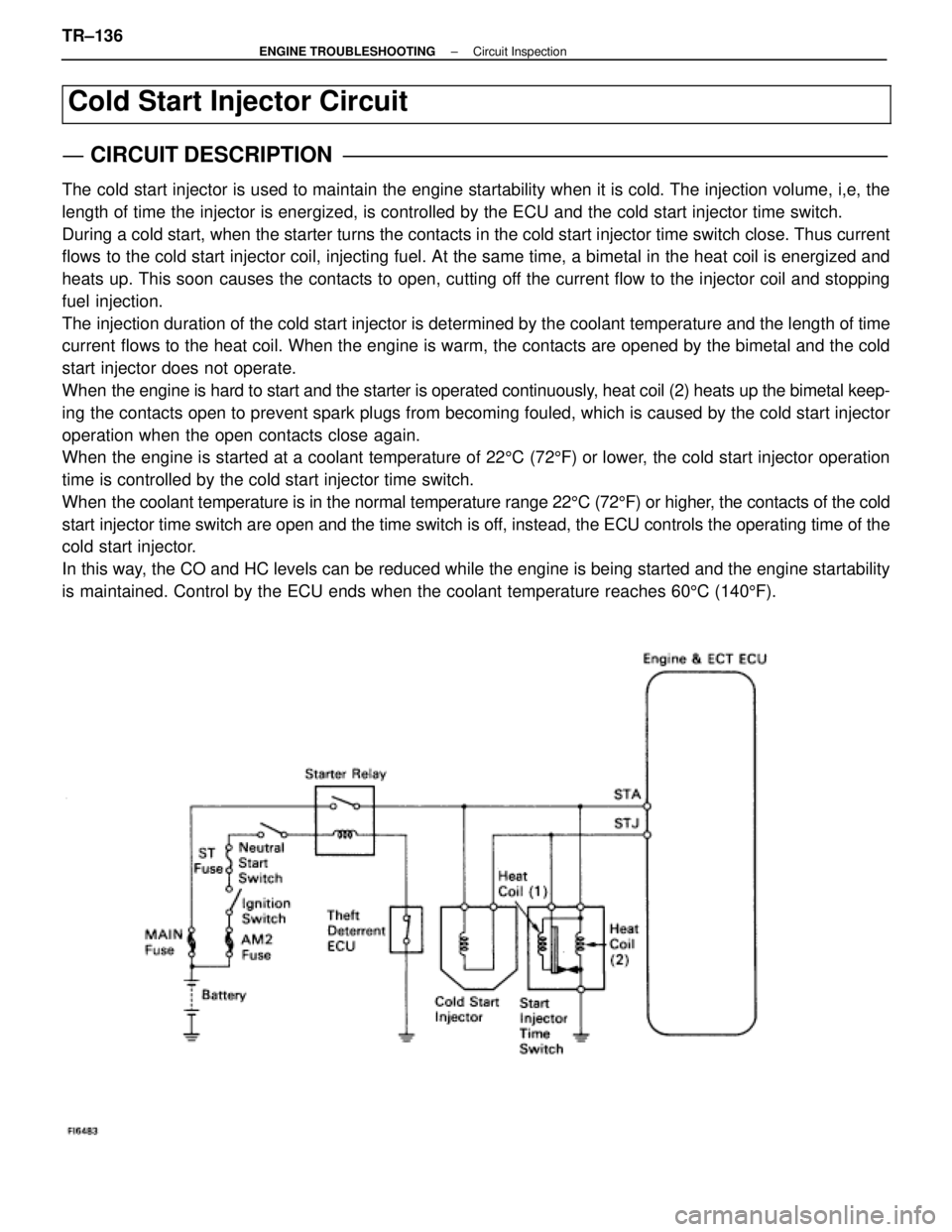
Cold Start Injector Circuit
CIRCUIT DESCRIPTION
The cold start injector is used to maintain the engine startability when it\
is cold. The injection volume, i,e, the
length of time the injector is energized, is controlled by the ECU and t\
he cold start injector time switch.
During a cold start, when the starter turns the contacts in the cold start inj\
ector time switch close. Thus current
flows to the cold start injector coil, injecting fuel. At the same time, a bi\
metal in the heat coil is energized and
heats up. This soon causes the contacts to open, cutting off the current flow to the injector coil and stopping
fuel injection.
The injection duration of the cold start injector is determined by the cool\
ant temperature and the length of time
current flows to the heat coil. When the engine is warm, the contacts are opened by the bimetal and the cold
start injector does not operate.
When the engine is hard to start and the starter is operated continuously, heat coil (2) heats up the bimetal keep-
ing the contacts open to prevent spark plugs from becoming fouled, which is\
caused by the cold start injector
operation when the open contacts close again.
When the engine is started at a coolant temperature of 225C (72 5F) or lower, the cold start injector operation
time is controlled by the cold start injector time switch.
When the coolant temperature is in the normal temperature range 22 5C (72 5F) or higher, the contacts of the cold
start injector time switch are open and the time switch is off, instead, the ECU controls the operating time of the
cold start injector.
In this way, the CO and HC levels can be reduced while the engine is being started \
and the engine startability
is maintained. Control by the ECU ends when the coolant temperature reac\
hes 60 5C (140 5F).
TR±136±
ENGINE TROUBLESHOOTING Circuit Inspection
WhereEverybodyKnowsYourName