Page 1520 of 4087

22. DISCONNECT POWER STEERING (PS) RESERVOIRTANK AND BRACKET FROM BODY
Remove the 3 bolts, and disconnect the reservoir tank and
bracket assembly.
23. DISCONNECT POWER STEERING (PS) PUMP FROM ENGINE
Remove the nut and 3 bolts, and disconnect the PS pump
from the engine.
HINT: Put aside the PS pump, and suspend it.
24. DISCONNECT AIR CONDITIONING (A/C) COMPRESSOR FROM ENGINE
(a) Disconnect the A/C compressor connector.
(b) Remove the nut, and disconnect the ground cable from the
A/C compressor stay.
(c) Remove the bolt and A/C compressor stay.
(d) Remove the 2 bolts, and disconnect the A/C compressor from the engine.
HINT: Put aside the A/C compressor, and suspend it.
25. DISCONNECT HOSES Disconnect the following hoses and ground strap:
(1) Heater water hose from water bypass hose
(2) Heater water hose from heater water valve
(3) Brake booster hose from union on air intake chamber
(4) Vacuum hose (from VSV for heater water valve) from air
intake chamber
(5) Ground strap from bracket on body.
EG±144
±
1UZ±FE ENGINE ENGINE MECHANICAL
WhereEverybodyKnowsYourName
Page 1573 of 4087
12. INSTALL CHARCOAL CANISTER
(a) Install the charcoal canister.
(b) Connect the vacuum hose and air hose to the charcoalcanister.
13. CONNECT HOSES Connect the following hoses and ground strap:
(1) Heater water hose to water bypass hose
(2) Heater water hose to heater water valve
(3) Brake booster hose to union on air intake chamber
(4) Vacuum hose (from VSV for heater water valve) to air in-
take chamber
(5) Ground strap to bracket on body
(6) Fuel inlet hose to fuel tube
SST 09278±54012
Torque: 30 N Vm (310 kgf Vcm, 22 ft Vlbf)
HINT: Use a torque wrench with a fulcrum length of 30 cm
(11.81 in.).
(7) Fuel return hose to return pipe
14. INSTALL AIR CONDITIONING (A/C) COMPRESSOR
(a) Install the A/C compressor, compressor stay and ground cable with the nut and 3 bolts.
Torque:
49 NVm (500 kgf Vcm, 36 ft Vlbf) for bolt
29 N Vm (300 kgf Vcm, 22 ft Vlbf) for nut
(b) Connect the A/C compressor connector.
±
1UZ±FE ENGINE ENGINE MECHANICALEG±197
WhereEverybodyKnowsYourName
Page 1574 of 4087
15. INSTALL POWER STEERING (PS) PUMP
(a) Install the PS pump with the nut and 3 bolts. Alternatelytighten the bolts and nut.
Torque:
39 NVm (400 kgf Vcm, 29 ft Vlbf) for bolt
43 N Vm (440 kgf Vcm, 32 ft Vlbf) for nut
16. INSTALL POWER STEERING (PS) RESERVOIR TANK
AND BRACKET
Install the reservoir tank and bracket assembly with the 3
bolts.
17. INSTALL POWER STEERING (PS) TUBES Install the PS tube clamp with the bolt.
18. INSTALL GENERATOR
(a) Install the generator and transmission oil cooler pipe bracket with the bolt and nut.
Torque: 37 N Vm (380 kgf Vcm, 27 ft Vlbf)
(b) Connect the generator connector.
(c) Connect the generator wire with the nut and cap.
19. INSTALL WIRE CLAMP (FOR GENERATOR) AND VSV
(FOR EVAP)
(a) Install the wire clamp to the VSV bracket.
(b) Install the VSV with the 2 bolts.
EG±198
±
1UZ±FE ENGINE ENGINE MEHANICAL
WhereEverybodyKnowsYourName
Page 1587 of 4087
15. DISCONNECT ENGINE WIRE CONNECTORS
16. DISCONNECT THEFT DETERRENT HORN CONNECTOR
17. DISCONNECT GROUND CABLE FROM BODY
18. DISCONNECT PS SOLENOID VALVE CONNECTOR
19. DISCONNECT WIRE CLAMP (FOR ALTERNATOR) FROMVSV (FOR EVAP SYSTEM)
(a) Remove the two bolts, and disconnect the VSV from the
RH cylinder head.
(b) Disconnect the wire clamp from the VSV bracket.
20. REMOVE ALTERNATOR (a) Disconnect the alternator connector.
(b) Remove the cap and nut, and disconnect the alternatorwire.
(c) Remove the mounting bolt and nut.
(d) Disconnect the A/T oil cooler pipe bracket.
(e) Remove the alternator.
21. D I S C O N N E C T P S T U B E S F R O M S U SPENSION
CROSSMEMBER
Remove the clamp bolt, and disconnect the PS tubes.
EM±122
±
ENGINE MECHANICAL Cylinder Block
WhereEverybodyKnowsYourName
Page 1588 of 4087

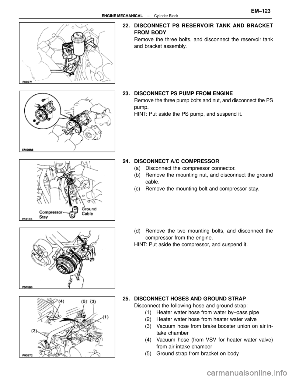
22. DISCONNECT PS RESERVOIR TANK AND BRACKET
FROM BODY
Remove the three bolts, and disconnect the reservoir tank
and bracket assembly.
23. DISCONNECT PS PUMP FROM ENGINE Remove the three pump bolts and nut, and disconnect the PS
pump.
HINT: Put aside the PS pump, and suspend it.
24. DISCONNECT A/C COMPRESSOR (a) Disconnect the compressor connector.
(b) Remove the mounting nut, and disconnect the groundcable.
(c) Remove the mounting bolt and compressor stay.
(d) Remove the two mounting bolts, and disconnect the compressor from the engine.
HINT: Put aside the compressor, and suspend it.
25. DISCONNECT HOSES AND GROUND STRAP Disconnect the following hose and ground strap:(1) Heater water hose from water by±pass pipe
(2) Heater water hose from heater water valve
(3) Vacuum hose from brake booster union on air in-
take chamber
(4) Vacuum hose (from VSV for heater water valve)
from air intake chamber
(5) Ground strap from bracket on body
±
ENGINE MECHANICAL Cylinder BlockEM±123
WhereEverybodyKnowsYourName
Page 1636 of 4087
(g) Install the scuff plate.
(h) Connect the connectors.
(i) Install the lower instrument panel finish panel and glovecompartment door assembly with the four screws.
(j) Install the instrument panel under cover with the two clips.
12. INSTALL CHARCOAL CANISTER (a) Install the charcoal canister.
(b) Connect the vacuum hose and air hose to the charcoalcanister.
13. CONNECT HOSES Connect the following hose and ground strap:(1) Heater water hose to water by±pass pipe
(2) Heater water hose to heater water valve
(3) Vacuum hose to brake booster union on air intake
chamber
(4) Vacuum hose (from VSV for heater water valve) to
air intake chamber
(5) Ground strap to bracket on body
±
ENGINE MECHANICAL Cylinder BlockEM±171
WhereEverybodyKnowsYourName
Page 1638 of 4087
17. INSTALL PS TUBESInstall the PS tube clamp with the bolt.
18. INSTALL ALTERNATOR (a) Install the alternator and A/T oil cooler pipe bracket withthe bolt and nut.
Torque: 37 N Vm (380 kgf Vcm, 27 ft Vlbf)
(b) Connect the alternator connector.
(c) Connect the alternator wire with the nut and cap.
19. INSTALL WIRE CLAMP (FOR ALTERNATOR) AND VSV (FOR EVAP SYSTEM)
(a) Install the wire clamp to the VSV bracket.
(b) Install the VSV with the two bolts.
20. CONNECT PS SOLENOID VALVE CONNECTOR
21. CONNECT ENGINE WIRE CONNECTORS
22. CONNECT THEFT DETERRENT HORN CONNECTOR
23. INSTALL GROUND CABLE TO BODY
±
ENGINE MECHANICAL Cylinder BlockEM±173
WhereEverybodyKnowsYourName
Page 1658 of 4087

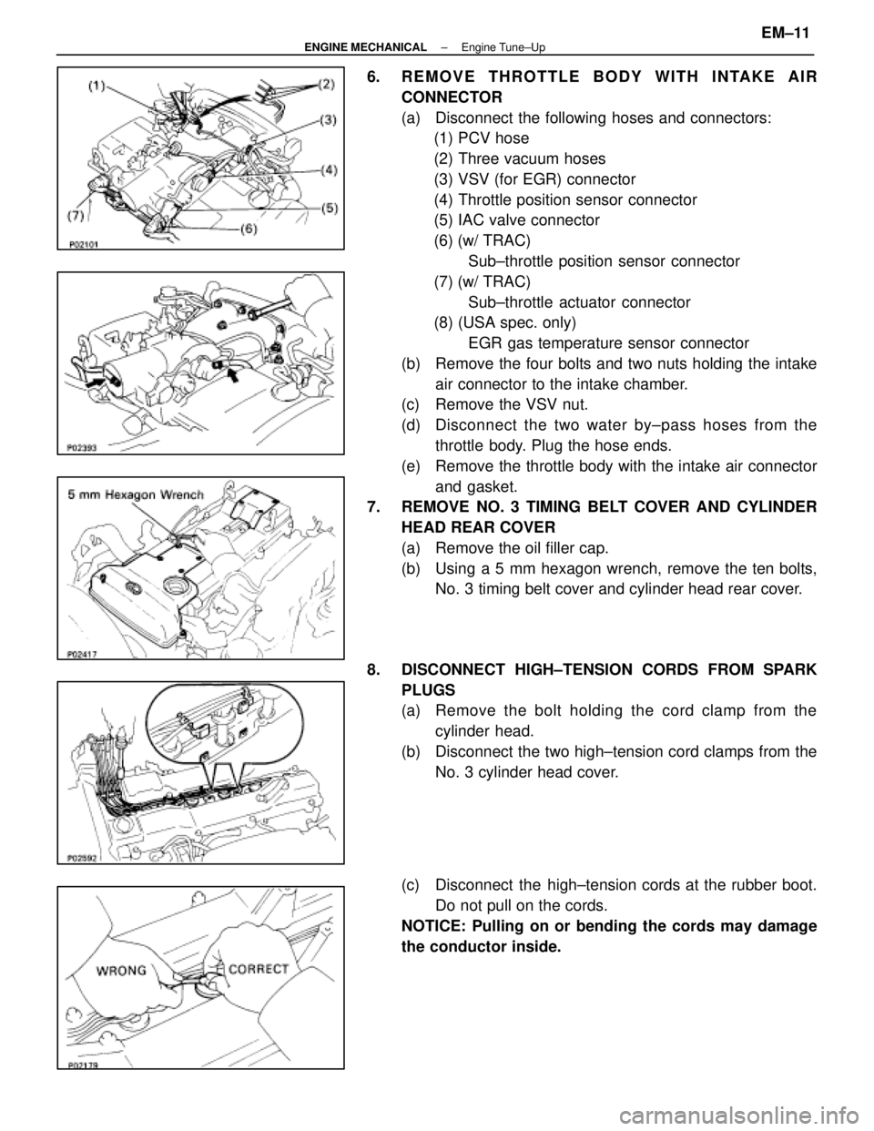
6. REMOVE THROTTLE BODY WITH INTAKE AIRCONNECTOR
(a) Disconnect the following hoses and connectors:(1) PCV hose
(2) Three vacuum hoses
(3) VSV (for EGR) connector
(4) Throttle position sensor connector
(5) IAC valve connector
(6) (w/ TRAC)
Sub±throttle position sensor connector
(7) (w/ TRAC) Sub±throttle actuator connector
(8) (USA spec. only)
EGR gas temperature sensor connector
(b) Remove the four bolts and two nuts holding the intake air connector to the intake chamber.
(c) Remove the VSV nut.
(d) Disc onnect the two water by±pass hoses from the
throttle body. Plug the hose ends.
(e) Remove the throttle body with the intake air connector and gasket.
7. REMOVE NO. 3 TIMING BELT COVER AND CYLINDER
HEAD REAR COVER
(a) Remove the oil filler cap.
(b) Using a 5 mm hexagon wrench, remove the ten bolts,No. 3 timing belt cover and cylinder head rear cover.
8. DISCONNECT HIGH±TENSION CORDS FROM SPARK PLUGS
(a) Remove the bolt holding the cord clamp from thecylinder head.
(b) Disconnect the two high±tension cord clamps from the No. 3 cylinder head cover.
(c) Disconnect the high±tension cords at the rubber boot. Do not pull on the cords.
NOTICE: Pulling on or bending the cords may damage
the conductor inside.
±
ENGINE MECHANICAL Engine Tune±UpEM±11
WhereEverybodyKnowsYourName