Page 643 of 4087
28CD playerSOUND QUALITY POOR
Is radio operating normally?
Is speaker properly installed? Temporarily install another speaker
Functions OK? Temporarily install another CD auto changer.
Functions OK?
Temporarily install another power amplifier.
Functions OK? Radio receiver assembly faulty. Speaker faulty. Speaker installation faulty
Power amplifier faulty. Radio receiver assem-
bly faulty CD changer faulty.
29CD playerVOLUME REMAINS AT MAXIMUM LEVEL
Is radio operating normally?
Radio receiver assembly faulty.
Wire harness faulty.
Is there continuity between the following terminals
with connector disconnected?
� Radio receiver assembly B1 ± Power switch 14
� Radio receiver assembly B3 ± Power switch 11
Power switch faulty.
Radio receiver assembly faulty.
When the volume switch is turned from minimum to
maximum, does resistance between terminal 11±14
of power switch changes from 0 to 50 k
�?
±
BODY ELECTRICAL SYSTEM AUDIO SYSTEMBE±257
WhereEverybodyKnowsYourName
Page 803 of 4087

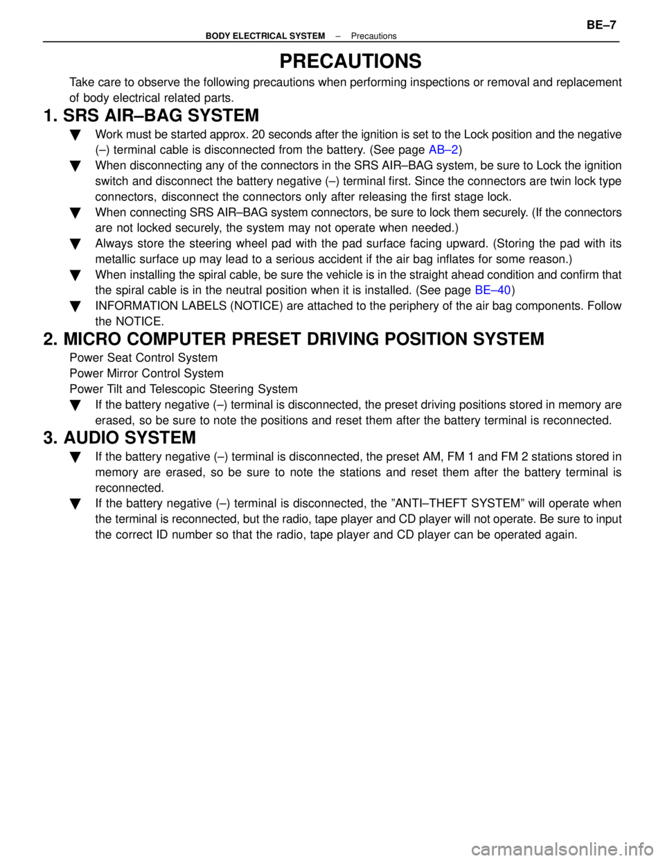
PRECAUTIONS
Take care to observe the following precautions when performing inspection\
s or removal and replacement
of body electrical related parts.
1. SRS AIR±BAG SYSTEM
�Work must be started approx. 20 seconds after the ignition is set to the Loc\
k position and the negative
(±) terminal cable is disconnected from the battery. (See page AB±2)
� When disconnecting any of the connectors in the SRS AIR±BAG system, be su\
re to Lock the ignition
switch and disconnect the battery negative (±) terminal first. Since the connectors are twin \
lock type
connectors, disconnect the connectors only after releasing the first stage lock.
� When connecting SRS AIR±BAG system connectors, be sure to lock them secur\
ely. (If the connectors
are not locked securely, the system may not operate when needed.)
� Always store the steering wheel pad with the pad surface facing upward. (Stor\
ing the pad with its
metallic surface up may lead to a serious accident if the air bag inflates for s\
ome reason.)
� When installing the spiral cable, be sure the vehicle is in the straight ahe\
ad condition and confirm that
the spiral cable is in the neutral position when it is installed. (See pag\
e BE±40)
� INFORMATION LABELS (NOTICE) are attached to the periphery of the air bag componen\
ts. Follow
the NOTICE.
2. MICRO COMPUTER PRESET DRIVING POSITION SYSTEM
Power Seat Control System
Power Mirror Control System
Power Tilt and Telescopic Steering System
�If the battery negative (±) terminal is disconnected, the preset driv\
ing positions stored in memory are
erased, so be sure to note the positions and reset them after the battery termi\
nal is reconnected.
3. AUDIO SYSTEM
�If the battery negative (±) terminal is disconnected, the preset AM, F\
M 1 and FM 2 stations stored in
memory are erased, so be sure to note the stations and reset them after the battery terminal is
reconnected.
� If the battery negative (±) terminal is disconnected, the ºANTI±\
THEFT SYSTEMº will operate when
the terminal is reconnected, but the radio, tape player and CD player will \
not operate. Be sure to input
the correct ID number so that the radio, tape player and CD player can be o\
perated again.
±
BODY ELECTRICAL SYSTEM PrecautionsBE±7
WhereEverybodyKnowsYourName
Page 3851 of 4087
204
AUTO ANTENNA
Bc1
9Bc1 24 Bc1 23 Bc1 8 C
C
D
D
M
3614 11912134
2
1
4
5
8
6
3
78 10
5
2 7
+B IG ACC ANT+B AMP+B ANTB ANTA GND
UP DOWN S VCC SIG SGND
L±YY
R±G
BR
R±W L±B
L±GW±B
IC
SENSOR +
± P±G
P±L
Y±R
L±W
W±B
W±B
8
9
10 4
P±L
P±G
L±Y
B±R
GR
P±GP±L
Y±R
L±W
P±G
P±L
Y±R
L±W
RADIO AND TAPE RLAYER
AUTO ANTENNA MOTOR AND RELAY A3 2
B
G
R
L
B±Y
FROM POWER SOURCE SYSTEM
(
SEE PAGE 56 )
12 1 2
3
AUTO ANTENNA CONTROL RELAY
AUTO ANTENNA MOTOR
BM
2
7
1C
61E 10 C
3
A 3
A 8
A 1
B
10
B4
BV1
7
BV1
18
BV1
4
BV1
19
Bc1
10
Bc2
1 IE 1
2
IG2
3
IQ2
11
BV2
7 BV1 2IQ1
3
I31
L±Y
L±Y
L±Y
L±Y
L±Y
GR
GR
GR
GR
GR
GR R2 ,R4 ,R5
D
BAC
(
W/ CD PLAYER )
( W/O CD PLAYER )
8
A
B
A32
20A
RADIO
NO. 1 15A
ECU±IG
7. 5A
RADIO
NO. 2 GR
( W/O CD PLAYER )
( W/ CD PLAYER )
GR
( W/ CD PLAYER )
(W/O CD PLAYER )
WhereEverybodyKnowsYourName
Page 3852 of 4087

4
XXXX10 4
XXXX10
BDB
R2 R2
A32
12 3
45678 A
A32
13
8X A
R4
3
89
C
R5
X23 456
7891011121314
205
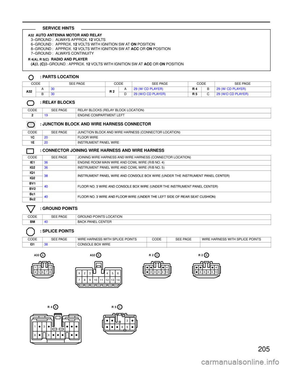
A32 AUTO ANTENNA MOTOR AND RELAY
3±GROUND : ALWAYS APPROX. 12 VOLTS
6±GROUND : APPROX. 12 VOLTS WITH IGNITION SW AT ON POSITION
8±GROUND : APPROX. 12 VOLTS WITH IGNITION SW AT ACC OR ON POSITION
7±GROUND : ALWAYS CONTINUITY
R 4(A), R 5(C) RADIO AND PLAYER
(A) 3, (C) 3±GROUND : APPROX. 12 VOLTS WITH IGNITION SW AT ACC OR ON POSITION
: PARTS LOCATION
CODESEE PAGECODESEE PAGECODESEE PAGE
A32A30R2A29 (W/ CD PLAYER)R 4B29 (W/ CD PLAYER)A32B30R 2D29 (W/O CD PLAYER)R 5C29 (W/O CD PLAYER)
: RELAY BLOCKS
CODESEE PAGERELAY BLOCKS (RELAY BLOCK LOCATION)
219ENGINE COMPARTMENT LEFT
: JUNCTION BLOCK AND WIRE HARNESS CONNECTOR
CODESEE PAGEJUNCTION BLOCK AND WIRE HARNESS (CONNECTOR LOCATION)
1C20FLOOR WIRE
1E20INSTRUMENT PANEL WIRE
: CONNECTOR JOINING WIRE HARNESS AND WIRE HARNESS
CODESEE PAGEJOINING WIRE HARNESS AND WIRE HARNESS (CONNECTOR LOCATION)
IE136ENGINE ROOM MAIN WIRE AND COWL WIRE (R/B NO. 4)
IG236INSTRUMENT PANEL WIRE AND COWL WIRE (R/B NO. 5)
IQ138INSTRUMENT PANEL WIRE AND CONSOLE BOX WIRE (UNDER THE INSTRUMENT PANEL CENTER)IQ238INSTRUMENT PANEL WIRE AND CONSOLE BOX WIRE (UNDER THE INSTRUMENT PANEL CENTER)
BV140FLOOR NO 3 WIRE AND CONSOLE BOX WIRE (UNDER THE INSTRUMENT PANEL CENTER)BV240FLOOR NO. 3 WIRE AND CONSOLE BOX WIRE (UNDER THE INSTRUMENT PANEL CENTER)
Bc140FLOOR NO 3 WIRE AND FLOOR WIRE (UNDER THE LEFT SIDE OF REAR SEAT CUSHION)Bc240FLOOR NO. 3 WIRE AND FLOOR WIRE (UNDER THE LEFT SIDE OF REAR SEAT CUSHION)
: GROUND POINTS
CODESEE PAGEGROUND POINTS LOCATION
BM40BACK PANEL CENTER
: SPLICE POINTS
CODESEE PAGEWIRE HARNESS WITH SPLICE POINTSCODESEE PAGEWIRE HARNESS WITH SPLICE POINTS
I3138CONSOLE BOX WIRE
SERVICE HINTS
WhereEverybodyKnowsYourName
Page 3855 of 4087
207
Bc1
17 Bc1 5Bc116 Bc1 19 Bc 1 20 Bc24Bc23
BBA BAA B
B
BCC
12 18 23 10 5 3 9
4
10
451 1
6
5 22 25 19 6 2 1
D3 GND3 GND2 MUTE RLI+ RLI± RLO+
RLO±
D3 GND2 GND1 TEL+ TEL± SP±CUT
GND AUD+ AUD± SP+
SP±
188 4512 5
12
415
Y±B
L
B
W±B B±R B±YL±B
V
LG
LL LG
V
L
LG
V
B±R B±Y
L±B
B
Y
O
B B BR
R±B BR
R±B
TLMT FR+ FR±
MOBILEPHONE RADIO AND PLAYER
TELEPHONE TRANSCEIVER AND SPEAKER RELAY T16
,T17
M1 R4,
R5 ,R
6
A
B
B
D2 3 4
D2
11
6
R
L±Y
L±Y
Y
G±WR±W
L±W
B±W
SPEAKER RELAY
L
BV1
10 BV2 2BV21
(
W/O CD PLAYER )
(
W/O CD PLAYER )
( W/ CD PLAYER )
( W/ CD PLAYER )
15
STEREO POWER
AMPLIFIER
LG L
FR+ FR±
S14
1
2
IP1
10
IP1 1 BT1
5
BT1 6
L
LG
LG L LG
L
FRONT DOOR
SPEAKER RH
F1 2
TELEPHONE TRANSCEIVER
A
3
(
W/ CD PLAYER )
(
W/O CD PLAYER )
A
BC
WhereEverybodyKnowsYourName
Page 3856 of 4087

208
CELLULAR MOBILE TELEPHONE
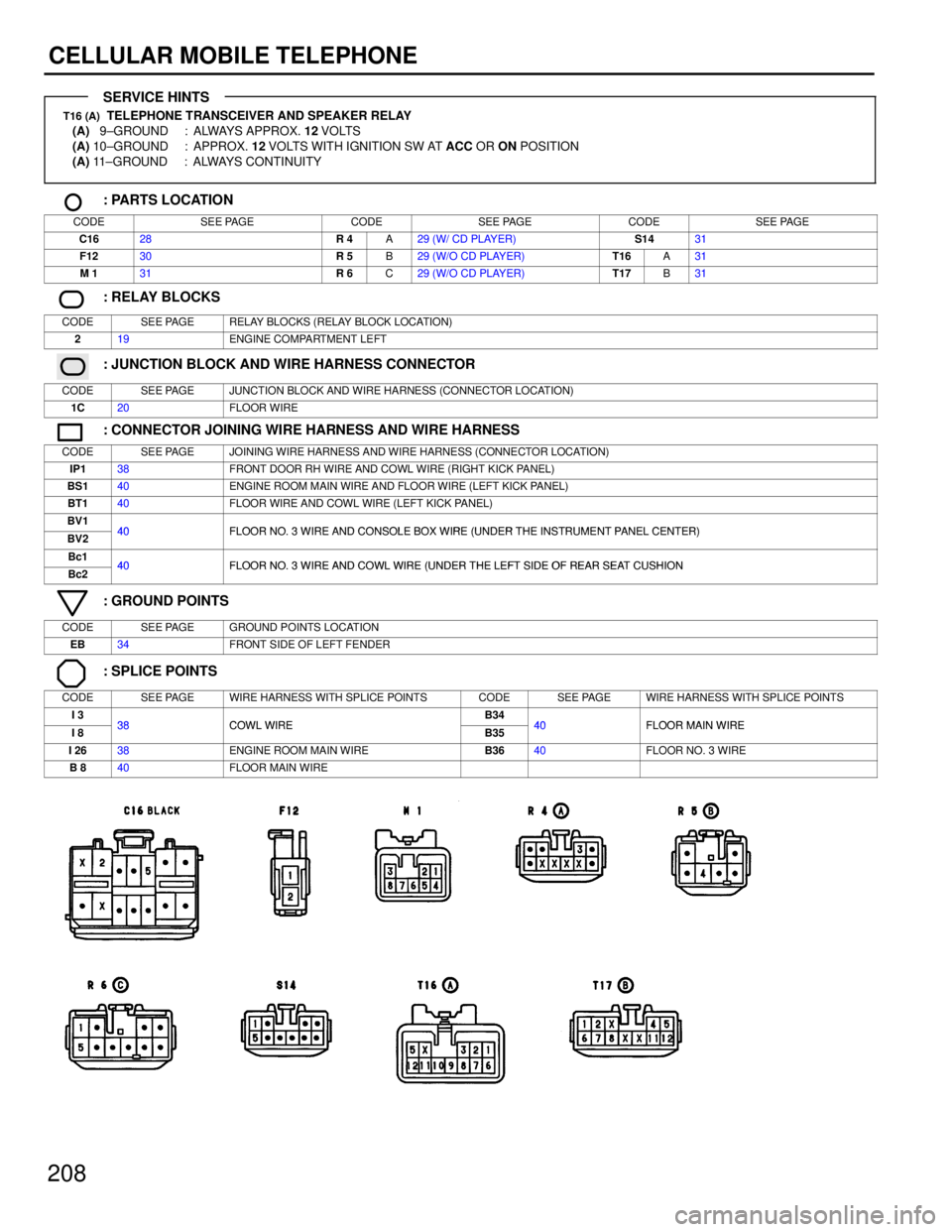
T16 (A) TELEPHONE TRANSCEIVER AND SPEAKER RELAY
(A) 9±GROUND : ALWAYS APPROX. 12 VOLTS
(A) 10±GROUND : APPROX. 12 VOLTS WITH IGNITION SW AT ACC OR ON POSITION
(A) 11±GROUND : ALWAYS CONTINUITY
: PARTS LOCATION
CODESEE PAGECODESEE PAGECODESEE PAGE
C1628R 4A29 (W/ CD PLAYER)S1431
F1230R 5B29 (W/O CD PLAYER)T16A31
M 131R 6C29 (W/O CD PLAYER)T17B31
: RELAY BLOCKS
CODESEE PAGERELAY BLOCKS (RELAY BLOCK LOCATION)
219ENGINE COMPARTMENT LEFT
: JUNCTION BLOCK AND WIRE HARNESS CONNECTOR
CODESEE PAGEJUNCTION BLOCK AND WIRE HARNESS (CONNECTOR LOCATION)
1C20FLOOR WIRE
: CONNECTOR JOINING WIRE HARNESS AND WIRE HARNESS
CODESEE PAGEJOINING WIRE HARNESS AND WIRE HARNESS (CONNECTOR LOCATION)
IP138FRONT DOOR RH WIRE AND COWL WIRE (RIGHT KICK PANEL)
BS140ENGINE ROOM MAIN WIRE AND FLOOR WIRE (LEFT KICK PANEL)
BT140FLOOR WIRE AND COWL WIRE (LEFT KICK PANEL)
BV140FLOOR NO 3 WIRE AND CONSOLE BOX WIRE (UNDER THE INSTRUMENT PANEL CENTER)BV240FLOOR NO. 3 WIRE AND CONSOLE BOX WIRE (UNDER THE INSTRUMENT PANEL CENTER)
Bc140FLOOR NO 3 WIRE AND COWL WIRE (UNDER THE LEFT SIDE OF REAR SEAT CUSHIONBc240FLOOR NO. 3 WIRE AND COWL WIRE (UNDER THE LEFT SIDE OF REAR SEAT CUSHION
: GROUND POINTS
CODESEE PAGEGROUND POINTS LOCATION
EB34FRONT SIDE OF LEFT FENDER
: SPLICE POINTS
CODESEE PAGEWIRE HARNESS WITH SPLICE POINTSCODESEE PAGEWIRE HARNESS WITH SPLICE POINTS
I 338COWL WIREB3440FLOOR MAIN WIREI 838COWL WIREB3540FLOOR MAIN WIRE
I 2638ENGINE ROOM MAIN WIREB3640FLOOR NO. 3 WIRE
B 840FLOOR MAIN WIRE
SERVICE HINTS
WhereEverybodyKnowsYourName
Page 3870 of 4087

28
ELECTRICAL WIRING ROUTING
Position of Parts in Instrument Panel
A 12 A/C Control Assembly C 9 CD Player
A 13 A/C Control Assembly C 10 Center Airbag Sensor Assembly
A 14 A/C Control Assembly C 11 Cigarette Lighter
A 15 A/C Control SW and Radio SW C 12 Combination Meter
A 16 A/C Evaporator Temp. Sensor C 13 Combination Meter
A 17 A/C Power Transistor C 14Combination Meter
A 18 A/C Power Transistor C 15 Combination SW
A 19 A/C Room Temp. Sensor C 16 Combination SW
A 20 A/C Solar Sensor C 17 Combination SW
A 21 A/T Indicator Light (for Shift Lever) C 19 Cruise Control ECU
A 22 ABS ECU (for M/T, w/o Traction Control) C 23 Clutch Start SW
A 23 ABS ECU (for M/T, w/o Traction Control) C 24 Cruise Control Clutch SW
A 24 ABS and Traction ECU
A 25 ABS and Traction ECU D 1 Diode (for Brake Fluid Level)
A 26 ABS and Traction ECU D 2 Diode (for Parking Brake)
A 27 Air Mix Control Servo Motor D 3 Diode (for Tension Reduser)
A 28 Air Vent Mode Control Servo Motor
A 29 Airbag Squib E 8 ECT Pattern Select SW
A 33 Air Inlet Control Servo Motor E 9 Engine and ECT ECU (for A/T) E 10 Engine and ECT ECU (for A/T)
B 2 Blower Motor E 11 Engine ECU (for M/T)
B 3 Blower Resistor (for Low Speed) E 12 Engine ECU (for M/T)
F 10 Fuel Lid Opener SW
G 1 Glove Box Light
G 2 Glove Box Light SW
WhereEverybodyKnowsYourName
Page 3871 of 4087

29
Position of Parts in Instrument Panel
H 7 Hazard SW S 10 Shift Lock ECUS 11 Step Light
I 14 Ignition Key Cylinder Light S 12 Stop Light SW
I 15 Ignition SW, Unlock Warning SW and Key Inter Lock Solenoid S 22 Short Connector
I 16 Integration Relay S 23 Short Connector S 24 Seat Heater SW (for M/T)
K 3 Kick Down SW T 6 TDCL (Total Diagnostic Communication Link)
L 1 Luggage Compartment Door Open SW T 7 Telescopic Position Sensor T 8 Theft Deterrent and Door Lock Control ECU
N 4 Noise Filter (for A/C System) T 9 Theft Deterrent and Door Lock Control ECU T 10 Tilt and Power Telescopic ECU
O 5 O/D Main SW T 11 Tilt and Power Telescopic ECU T 12 Traction Cut SW and Seat Heater SW (for A/T)
P 2 PPS ECU T 13 Traction ECU (for A/T)
P 3 Parking Brake SW T 14 Traction ECU (for A/T) T 15 Trip SW and Theft Deterrent Indicator Light
R 2 Radio and Player
R 3 Radio and Player W 6 Water Temp. Sensor (for A/C System)
R 4 Radio and Player (w/ CD Player) W 7 Wireless Door Lock Main SW
R 5 Radio and Player (w/o CD Player)
R 6 Radio and Player (w/o CD Player)
R 7 Remote Control Mirror ECU
R 8 Remote Control Mirror ECU
R 9 Rheostat
WhereEverybodyKnowsYourName