Page 2373 of 4087
17. INSTALL PS TUBESInstall the PS tube clamp with the bolt.
18. INSTALL ALTERNATOR (a) Install the alternator and A/T oil cooler pipe bracket withthe bolt and nut.
Torque: 37 N Vm (380 kgf Vcm, 27 ft Vlbf)
(b) Connect the alternator connector.
(c) Connect the alternator wire with the nut and cap.
19. INSTALL WIRE CLAMP (FOR ALTERNATOR) AND VSV (FOR EVAP SYSTEM)
(a) Install the wire clamp to the VSV bracket.
(b) Install the VSV with the two bolts.
20. CONNECT PS SOLENOID VALVE CONNECTOR
21. CONNECT ENGINE WIRE CONNECTORS
22. CONNECT THEFT DETERRENT HORN CONNECTOR
23. INSTALL GROUND CABLE TO BODY
±
ENGINE MECHANICAL Cylinder BlockEM±173
WhereEverybodyKnowsYourName
Page 3120 of 4087

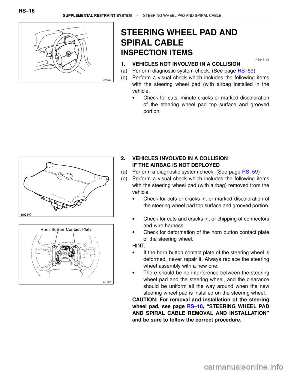
STEERING WHEEL PAD AND
SPIRAL CABLE
INSPECTION ITEMS
RS04B±01
1. VEHICLES NOT INVOLVED IN A COLLISION
(a) Perform diagnostic system check. (See page RS±59)
(b) Perform a visual check which includes the following items with the steering wheel pad (with airbag installed in the
vehicle.
wCheck for cuts, minute cracks or marked discoloration
of the steering wheel pad top surface and grooved
portion.
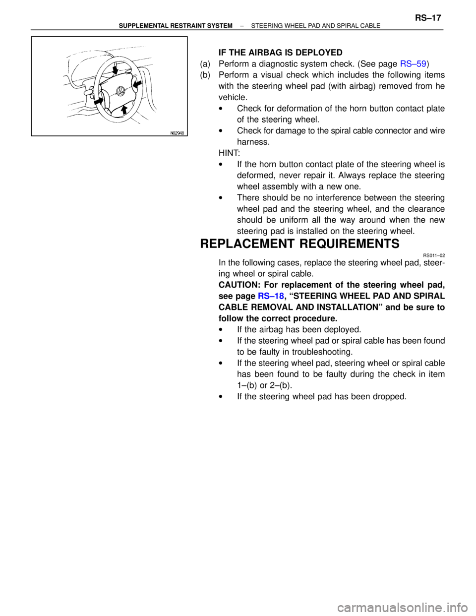
2. VEHICLES INVOLVED IN A COLLISION IF THE AIRBAG IS NOT DEPLOYED
(a) Perform a diagnostic system check. (See page RS±59)
(b) Perform a visual check which includes the following items with the steering wheel pad (with airbag) removed from the
vehicle.
wCheck for cuts or cracks in, or marked discoloration of
the steering wheel pad top surface and grooved portion.
w Check for cuts and cracks in, or chipping of connectors
and wire harness.
w Check for deformation of the horn button contact plate
of the steering wheel.
HINT:
w If the horn button contact plate of the steering wheel is
deformed, never repair it. Always replace the steering
wheel assembly with a new one.
w There should be no interference between the steering
wheel pad and the steering wheel, and the clearance
should be uniform all the way around when the new
steering wheel pad is installed on the steering wheel.
CAUTION: For removal and installation of the steering
wheel pad, see page RS±18, ªSTEERING WHEEL PAD
AND SPIRAL CABLE REMOVAL AND INSTALLATIONº
and be sure to follow the correct procedure.
RS±16
±
SUPPLEMENTAL RESTRAINT SYSTEM STEERING WHEEL PAD AND SPIRAL CABLE
WhereEverybodyKnowsYourName
Page 3121 of 4087

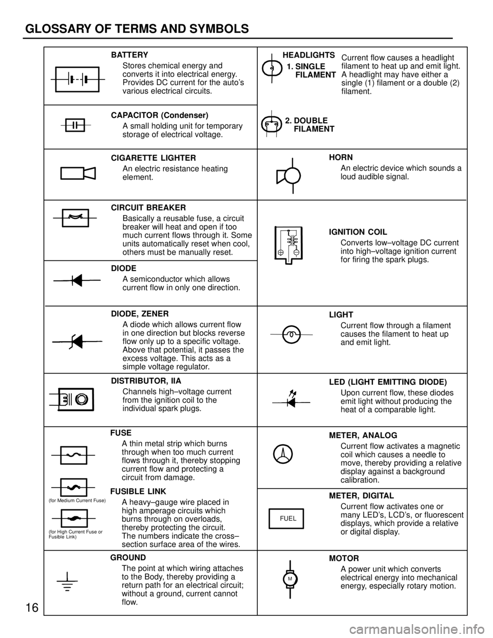
IF THE AIRBAG IS DEPLOYED
(a) Perform a diagnostic system check. (See page RS±59)
(b) Perform a visual check which includes the following items
with the steering wheel pad (with airbag) removed from he
vehicle.
wCheck for deformation of the horn button contact plate
of the steering wheel.
w Check for damage to the spiral cable connector and wire
harness.
HINT:
w If the horn button contact plate of the steering wheel is
deformed, never repair it. Always replace the steering
wheel assembly with a new one.
w There should be no interference between the steering
wheel pad and the steering wheel, and the clearance
should be uniform all the way around when the new
steering pad is installed on the steering wheel.
REPLACEMENT REQUIREMENTS
RS011±02
In the following cases, replace the steering wheel pad, steer-
ing wheel or spiral cable.
CAUTION: For replacement of the steering wheel pad,
see page RS±18, ªSTEERING WHEEL PAD AND SPIRAL
CABLE REMOVAL AND INSTALLATIONº and be sure to
follow the correct procedure.
w If the airbag has been deployed.
w If the steering wheel pad or spiral cable has been found
to be faulty in troubleshooting.
w If the steering wheel pad, steering wheel or spiral cable
has been found to be faulty during the check in item
1±(b) or 2±(b).
w If the steering wheel pad has been dropped.
±
SUPPLEMENTAL RESTRAINT SYSTEM STEERING WHEEL PAD AND SPIRAL CABLERS±17
WhereEverybodyKnowsYourName
Page 3868 of 4087

26
ELECTRICAL WIRING ROUTING
Position of Parts in Engine Compartment
A 1 A/C Ambient Temp. Sensor E 1 ECT Solenoid
A 2 A/C Lock Sensor and A/C Magnetic Clutch E 2 EFI Water Temp. Sensor
A 3 A/C High Pressure SW E 3 EGR Gas Temp. Sensor (for USA Spec.)
A 4 ABS Actuator E 5 Engine Hood Courtesy SW
A 5 ABS Actuator (w/ Traction Control) E 6 Engine Oil Level Warning SW
A 6 ABS Actuator (w/ Traction Control)
A 7 ABS Speed Sensor Front LH F 1 Front Airbag Sensor LH
A 8 ABS Speed Sensor Front RH F 2 Front Airbag Sensor RH
A 9 Air Flow Meter F 3 Front Clearance Light LH
A 10 Alternator F 4 Front Clearance Light RH
A 11 Alternator F 5Front Side Marker Light LH
A 33 ABS Actuator (w/o Traction Control) F 6 Front Side Marker Light RH F 7 Front Turn Signal Light LH
B 1 Brake Fluid Level SW F 8 Front Turn Signal Light RH
B 6 Back±Up Light SW (for M/T) F 9 Fuse Block
C 3 Check Connector H 1 Headlight Hi LH
C 6 Cornering Light LH H 2 Headlight Hi RH
C 7 Cornering Light RH H 3 Headlight Lo LH
C 8 Cruise Control Actuator H 4 Headlight Lo RH H 5 Horn LH
D 13 Distributor H 6 Horn RH
WhereEverybodyKnowsYourName
Page 3869 of 4087

27
Position of Parts in Engine Compartment
I 1 ISC Valve S 3Speed Sensor No. 1
I 2 Igniter S 4 Speed Sensor No. 2 (for ECT)
I 4 Ignition Coil S 6 Starter
I 6 Injector No. 1 S 7 Starter
I 7 Injector No. 2 S 8 Sub Throttle Actuator
I 8 Injector No. 3 S 9 Sub Throttle Position Sensor
I 9 Injector No. 4
I 10 Injector No. 5 T 1 Theft Deterrent Horn
I 11 Injector No. 6 T 2 Throttle Position Sensor T 3 Traction Brake Actuator
K 1 Knock Sensor No. 1 (on Front Side) T 4 Traction Brake Actuator
K 2 Knock Sensor No. 2 (on Rear Side) T 5 Traction pump and Motor
N 1 Neutral Start SW, Back±Up Light SW and A/T Indicator SW V 1 VSV (for EGR) (Exc. USA Spec) (for A/T) V 2 VSV (for EVAP)
N 2 Noise Filter (for Defogger System) V 4 VSV (for Water Valve)
N 3 Noise Filter (for Ignition System) V 7 VSV (for Intake Control Valve)
O 2 Oil Pressure SW W 1 Washer Level SW
O 3 Oxygen Sensor Main No. 1 (on Front Side) W 2 Washer Motor
O 4 Oxygen Sensor Main No. 2 (on Rear Side) W 3 Water Temp. Sender W 5 Wiper Motor
P 1 PPS Solenoid
P 20 Power Steering Pressure SW
WhereEverybodyKnowsYourName
Page 3917 of 4087

METER, ANALOGCurrent flow activates a magnetic
coil which causes a needle to
move, thereby providing a relative
display against a background
calibration.
LED (LIGHT EMITTING DIODE)
Upon current flow, these diodes
emit light without producing the
heat of a comparable light.
IGNITION COIL
Converts low±voltage DC current
into high±voltage ignition current
for firing the spark plugs.
1. SINGLE
FILAMENT
GROUND
The point at which wiring attaches
to the Body, thereby providing a
return path for an electrical circuit;
without a ground, current cannot
flow. Current flow causes a headlight
filament to heat up and emit light.
A headlight may have either a
single (1) filament or a double (2)
filament.
BATTERY
Stores chemical energy and
converts it into electrical energy.
Provides DC current for the auto's
various electrical circuits.
CAPACITOR (Condenser) A small holding unit for temporary
storage of electrical voltage.
CIRCUIT BREAKER Basically a reusable fuse, a circuit
breaker will heat and open if too
much current flows through it. Some
units automatically reset when cool,
others must be manually reset.
DIODE A semiconductor which allows
current flow in only one direction.
DIODE, ZENER A diode which allows current flow
in one direction but blocks reverse
flow only up to a specific voltage.
Above that potential, it passes the
excess voltage. This acts as a
simple voltage regulator.
FUSE A thin metal strip which burns
through when too much current
flows through it, thereby stopping
current flow and protecting a
circuit from damage.
FUSIBLE LINK A heavy±gauge wire placed in
high amperage circuits which
burns through on overloads,
thereby protecting the circuit.
The numbers indicate the cross±
section surface area of the wires. HORN
An electric device which sounds a
loud audible signal.
LIGHT Current flow through a filament
causes the filament to heat up
and emit light.
METER, DIGITAL Current flow activates one or
many LED's, LCD's, or fluorescent
displays, which provide a relative
or digital display.
MOTOR A power unit which converts
electrical energy into mechanical
energy, especially rotary motion.
CIGARETTE LIGHTER
An electric resistance heating
element.
DISTRIBUTOR, IIA Channels high±voltage current
from the ignition coil to the
individual spark plugs. 2. DOUBLE
FILAMENT
HEADLIGHTS
FUEL
(for High Current Fuse or
Fusible Link)
(for Medium Current Fuse)
M
16
GLOSSARY OF TERMS AND SYMBOLS
WhereEverybodyKnowsYourName
Page 3927 of 4087
1
C15 H 5, H 6 BLACK
X XX
X
14 X
X
111
HORN
2
5
IE19
4
44 IE 18
14 11E2
FROM POWER SOURCE SYSTEM
(
SEE PAGE 56 )
WW 25A
HAZ±HORN
HORN
RELAYBB
BG± R
B
12
6
HORN
HORN SW
[COMB. SW]
RH
LH
H5 H6
C15
3
HORN RELAY
2±3 : CLOSED WITH HORN SW ON
: PARTS LOCATION
CODESEE PAGECODESEE PAGECODESEE PAGE
C1528H 526H 626
: RELAY BLOCKS
CODESEE PAGERELAY BLOCKS (RELAY BLOCK LOCATION)
219ENGINE COMPARTMENT LEFT
423LEFT KICK PANEL (J/B NO.1 LEFT)
: CONNECTOR JOINING WIRE HARNESS AND WIRE HARNESS
CODESEE PAGEJOINING WIRE HARNESS AND WIRE HARNESS (CONNECTOR LOCATION)
IE136ENGINE ROOM MAIN WIRE AND COWL WIRE (R/B NO.4)
: SPLICE POINTS
CODESEE PAGEWIRE HARNESS WITH SPLICE POINTSCODESEE PAGEWIRE HARNESS WITH SPLICE POINTS
E 234ENGINE ROOM MAIN WIRE
SERVICE HINTS
WhereEverybodyKnowsYourName
Page 3964 of 4087

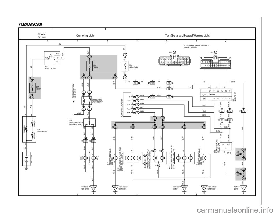
1234
7 LEXUS SC300
4ACC
IG1
ST 1
AM1 2
1J
7 1J
5
1B
4 1E
72
74
6 1
2
4
5
3
2
1C
4
1A
7
2 3EB 6
5 12 IQ1 10 IQ1
11 IQ1
10 IG1 23 I G1
IG2
8
IG2 9
IE1
9
IQ23
IQ2 13
IQ2 8
1H
11 1H 7
4
4 4
4
4
12
43
1E
19 1E 14 1C 31A4
3A
1
1J
1 3G
3
1E
18
IF
BM EA 10
3D
6
1K
2 3
23 B
16 A 17 A
5756
6
3
10 8 9
4 WW
W± RR± B
R±W G±Y
G±B W± R
G±R
WWW±B
G±R
W±RR±B
R± W
R± WR±B
W± B
G±R B±Y
W
R± W R±B
R± W
R±B
R± B
R±W
W± B
R±B
R±W
G±Y G±Y G±B
G±B
W±B
W±B
W±B
W±B
W±B
W± B
W± B
W±B W±B G±B
G±Y
WW
W±L W
W
B± Y
60A MAIN
100A AM1
120A ALT
I15
IGNITION SW 20A
TURN
25A
HA Z± HORN
TURN SIGNAL FLASHER
BATTERY
F7
F RONT T URN S I GNA L
LIGHT LH
R1 0
REAR TURN SI GNAL LI GHT LH
[REAR COMB. LIGHT LH]
R11
REAR TURN SIGNAL LIGHT RH
[ REAR COMB. LIGHT RH] F8
F RONT T URN S I GNA L
LIGHT RH C1 6
TURN SI GNAL SW
[COMB. SW]
TURN SIGNAL INDICATOR
LIGHT[ COMB. METER]
OFF
ON B1 F B2TLTBTR
H7
HA ZA RD SW
B
FOD FOE
FOG FOF
1I
1
1I
2
55 55
2 1 5
3
18 IE1
17 I E1
1 2 1
2
EA
8
11
10
W± G
G± R
G± R
W± B
W± B
W±B R±G
P± Y
R±G
P± Y R± YTo I ntegrat ion Relay
<5±2><4±2>
CORNERI NG
LIGHT RELAY
C16
CONE RI NG L I GHT
SW[COMB. SW]CORNERI NG LI GHT
C6
LH C7
RH
F9
FUSE BLOCK
Power
Source
Cornering Light Turn Signal and Hazard Warning Light40A
IGSW TURN SIGNAL INDICATOR LIGHT
[COMB. METER]
12 34 56 78
9 10 1112 13 14 1516 1718 17 18
1 2345 6789 10
23
22
21
20
19
15
14
13
12
11 16
AB
C13 C14
C13 A , C14 B
Front side of
r ight fender Fr ont side of
left fender Bac k panel
c enterFront side of
r ight fenderLeft kick
panel
6
5
WhereEverybodyKnowsYourName