Page 3198 of 4087
NGOK
INSPECTION PROCEDURE
1Preparation.
P1. Disconnect battery negative (±) terminal cable, andwait at least 90 seconds.
2. Remove steering wheel pad. (See page RS±19)
3. Disconnect connectors of front passenger airbag assembly (See page RS±32).
Caution: Store the steering wheel pad with the
surface facing upward.
2Check D squib circuit.
C
OK
PDisconnect center airbag sensor assembly connector.
Measure resistance between D+ and D± on spiral cable
side of connector between spiral cable and steering
wheel pad.
Resistance: Below 1 �
Go to Step �.
RS±94
±
SUPPLEMENTAL RESTRAINT SYSTEM TROUBLESHOOTING
WhereEverybodyKnowsYourName
Page 3199 of 4087
OKNG
OKNG
3Check spiral cable.
C
OK
PDisconnect connector between center airbag sensor
assembly and spiral cable.
Measure resistance between D
+ and D± on spiral cable
side of connector between spiral cable and steering
wheel pad.
Resistance: Below 1 �
Repair or replace spiral cable.
4Check harness between center airbag sensor assembly and spiral cable.
C
OK
Measure resistance between D+ and D± on center air-
bag sensor assembly side of connector between center
airbag sensor assembly and spiral cable.
Resistance: Below 1 �
Repair or replace harness or connector between center
airbag sensor assembly and spiral cable.
±
SUPPLEMENTAL RESTRAINT SYSTEM TROUBLESHOOTINGRS±95
WhereEverybodyKnowsYourName
Page 3200 of 4087

OKNG
OKNG
5Check center airbag sensor assembly.
C
OK
Hint
P1. Connect connector to center airbag sensor connec-
tor.
2. Connect connector between center airbag sensor assembly and spiral cable.
3. Using a service, wire, connect D
+ and D±. P+ and
P±.
4. Connect negative (±) terminal cable to battery and wait at least 2 second.
1. turn ignition switch ACC or ON, and wait at least 20
seconds.
Clear malfunction code. Turn ignition switch LOCK
and wait at least 20 seconds.
2. Turn ignition switch ACC or ON, and wait at least 20
seconds.
3. Using SST, connect terminals Tc and E
1 of DLC2.
SST 09843±18020
4. Check diagnostic trouble code.
Diagnostic trouble code 14 is not output.
Codes other than code 14 may be output at this time ,
but this is not relevant to this check.
Replace center airbag sensor assembly.
6Check D squib.
C
OK
Hint
P1. Turn ignition switch LOCK.
2. Disconnect battery negative (±) terminal cable, and wait at least 90 seconds.
3. Connect steering wheel pad (squib) connector.
4. Connect negative (±) terminal cable to battery, and wait at least 2 seconds.
1. Turn ignition switch ACC or ON, and wait at least 20
seconds.
Clear malfunction code. Turn ignition switch LOCK
and wait at least 20 seconds.
2. Turn ignition switch ACC or ON, and wait at least 20
seconds.
3. Using SST, connect terminals Tc and E
1 of DLC2.
SST 09843±18020
4. Check diagnostic trouble code.
Diagnostic trouble code 14 is not output.
Codes other t han code 14 may be output at this time, but
this is not relevant to this check.
Replace steering wheel pad.
From the results of the above inspection, the malfunctioning part can now be\
considered normal. To
make sure of this, use the simulation method to check.
RS±96±
SUPPLEMENTAL RESTRAINT SYSTEM TROUBLESHOOTING
WhereEverybodyKnowsYourName
Page 3203 of 4087
OKNG
INSPECTION PROCEDURE
1Preparation.
P1. Disconnect battery negative (±) terminal cable, andwait at least 90 seconds.
2. Remove steering wheel pad (See page RS±19).
3. Disconnect connectors of front passenger airbag assembly (See page RS±32).
Caution: Store the steering wheel pad with the
surface facing upward.
2Check front airbag sensor circuit (Measure resistance between terminals +SR \
and ±SR, +SL
and ±SL of center airbag sensor assembly connector.)
C
OK
PDisconnect center airbag sensor assembly connector.
Measure resistance between terminals +SR and ±SR,
+SL and ±SL of harness side connector of center airbag
sensor assembly.
Resistance: 755 � ± 885 �
Go to step �.
±
SUPPLEMENTAL RESTRAINT SYSTEM TROUBLESHOOTINGRS±99
WhereEverybodyKnowsYourName
Page 3204 of 4087

OKNG
3Check center airbag sensor assembly.
C
OK
Hint
P1. Connect connector to center airbag sensor assem-bly.
2. Using a service wire, connect D+ and D± on spiral cable side of connector between spiral cable and
steering wheel pad.
3. Using a service wire, connect P+ and P±n on center
airbag sensor assembly side of connector between
center airbag sensor assembly and front passen-
ger airbag.
4. Connect negative (±) terminal cable to battery, and wait at least 2 seconds.
1. Turn ignition switch AAC or ON, and wait at least 20 seconds.
Clear malfunction code. Turn ignition switch LOCK
and wait at least 20 seconds.
2. Turn ignition switch ACC or ON, and wait at least 20
seconds.
3. Using SST, connect terminals Tc and E
1 of DLC2.
SST 09843±18020
4. Check diagnostic trouble code.
Diagnostic trouble code 15 is not output.
Code other than code 15 may be output at this time, but
this is not relevant to this check.
Replace center airbag sensor assembly.
From the results of the above inspection, the malfunctioning part can now be\
considered normal. To
make sure of this, use the simulation method to check.
RS±100±
SUPPLEMENTAL RESTRAINT SYSTEM TROUBLESHOOTING
WhereEverybodyKnowsYourName
Page 3209 of 4087
OKNG
OKNG
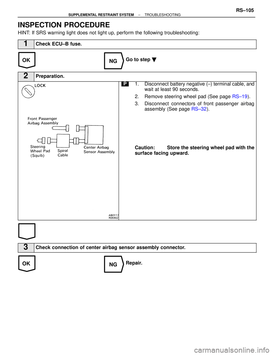
INSPECTION PROCEDURE
HINT: If SRS warning light does not light up, perform the following troublesh\
ooting:
1Check ECU±B fuse.
Go to step �
2Preparation.
P1. Disconnect battery negative (±) terminal cable, and
wait at least 90 seconds.
2. Remove steering wheel pad (See page RS±19).
3. Disconnect connectors of front passenger airbag assembly (See page RS±32).
Caution: Store the steering wheel pad with the
surface facing upward.
3Check connection of center airbag sensor assembly connector.
Repair.
±
SUPPLEMENTAL RESTRAINT SYSTEM TROUBLESHOOTINGRS±105
WhereEverybodyKnowsYourName
Page 3262 of 4087

������������������\
���� ������������������\
����Part tightened����� �����NVm������ ������kgf Vcm������ ������ft Vlbf
������������������\
���� ����������������")
TORQUE SPECIFICATIONS
SA0WG±03
(FRONT)
������������������\
���� ������������������\
����Part tightened����� �����NVm������ ������kgf Vcm������ ������ft Vlbf
������������������\
���� ������������������\
����Hub nut����� �����103������ ������1,050������ ������76
������������������\
���� ������������������\
����Front and rear adjusting cam bolt����� �����226������ ������2,300������ ������166
������������������\
���� ������������������\
����Axle hub lock nut����� �����199������ ������2,030������ ������147
������������������\
���� ������������������\
����Lower ball joint X Steering knuckle����� �����125������ ������1,270������ ������92
������������������\
���� ������������������\
����Tie rod end X Steering knuckle����� �����49������ ������500������ ������36
������������������\
���� ������������������\
����Steering knuckle X Upper suspension arm����� �����103������ ������1,050������ ������76
������������������\
���� ������������������\
����Lower ball foint X Lower suspension arm����� �����127������ ������1,300������ ������94
������������������\
���� ������������������\
����Disc brake caliper X Steering knuckle����� �����11 8������ ������1,200������ ������87
������������������\
���� ������������������\
����Speed sensor set bolt����� �����103������ ������80������ ������76 in. Vlbf
������������������\
���� ������������������\
����Front shock absorber X Body����� �����35������ ������360������ ������26
������������������\
���� ������������������\
����Front shock absorber X Lower suspension arm����� �����143������ ������1,460������ ������106
������������������\
���� ������������������\
����Upper suspension arm mounting nut����� �����164������ ������1,670������ ������121
������������������\
���� ������������������\
����Piston rod lock nut����� �����29������ ������300������ ������22
������������������\
���� ������������������\
����Stabilizer link X Lower suspension arm����� �����74������ ������750������ ������54
������������������\
���� ������������������\
����Stabilizer link X Stabilizer bar����� �����74������ ������750������ ������54
������������������\
���� ������������������\
����Stabilizer bar bracket X Body����� �����18������ ������180������ ������13
������������������\
���� ������������������\
����Steering knuckle X Disc brake dust cover����� �����19������ ������195������ ������14
(REAR)
������������������\
���� ������������������\
����Part tightened����� �����N Vm������ ������kgf Vcm������ ������ft Vlbf
������������������\
���� ������������������\
����Shock absorber X Lower suspension arm����� �����143������ ������1,460������ ������106������������������\
���� ������������������\
����Upper arm X Body����� �����164������ ������1,670������ ������271������������������\
���� ������������������\
����Rear axle carrier X Brake caliper����� �����104������ ������1,065������ ������77������������������\
���� ������������������\
����No. 1 lower arm X Rear axle carrier����� �����59������ ������600������ ������43������������������\
���� ������������������\
����No. 1 lower arm X Body����� �����184������ ������1,880������ ������136
������������������\
���� ������������������\
����No. 2 lower arm X Rear axle carrier����� �����150������ ������1,525������ ������11 0
������������������\
���� ������������������\
����No. 2 lower arm X Body����� �����184������ ������1,880������ ������136
������������������\
���� ������������������\
����Strut rod X Rear axle carrier����� �����184������ ������1,880������ ������136
������������������\
���� ������������������\
����Strut rod X Body����� �����184������ ������1,880������ ������136
������������������\
���� ������������������\
����Rear drive shaft X Axle hub����� �����289������ ������2,950������ ������213
������������������\
���� ������������������\
����Upper ball joint X Rear axle carrier����� �����109������ ������1,110������ ������80
������������������\
����Parking brake backing plate X Rear axle carrier�����26������260������19������������������\
���� ������������������\
����Rear drive shaft X Differential����� �����83������ ������850������ ������64������������������\
���� �
������������������\
���
������������������\
����Differential mounting bolt \
Front
Rear����� �
����
�����147
142������ �
�����
������1,500
1,450������ �
�����
������108
105
������������������\
���� ������������������\
����Differential carrier cover set bolt����� �����47������ ������475������ ������34
������������������\
���� ������������������\
����Suspension support X Body����� �����27������ ������280������ ������20
������������������\
���� ������������������\
����Suspension support X Shock absorber rod����� �����27������ ������280������ ������20
������������������\
���� ������������������\
����Stabilizer bar link nut����� �����74������ ������750������ ������54
������������������\
���� ������������������\
����Stabilizer bar bushing retainer bolt����� �����28������ ������290������ ������21
±
SUSPENSION AND AXLE SERVICE SPECIFICATIONSSA±129
WhereEverybodyKnowsYourName
Page 3267 of 4087
4. CHECK WHEEL BEARING LOOSENESS
(a) Check the backlash in bearing shaft direction.
Maximum: 0.05 mm (0.0020 in.)
(b) Check the axle hub deviation.
Maximum: 0.05 mm (0.0020 in.)
5. CHECK FRONT SUSPENSION FOR LOOSENESS
6. CHECK STEERING LINKAGE FOR LOOSENESS
7. CHECK BALL JOINT FOR EXCESSIVE LOOSENESS
8. CHECK SHOCK ABSORBER WORK PROPERLYwCheck for oil leak
w Check mounting busings for wear
w Bounce front and rear of the vehicle
SA±4
±
SUSPENSION AND AXLE GENERAL INSPECTION
WhereEverybodyKnowsYourName
 terminal cable, andwait at least 90 seconds.
2. Remove steering wheel pad. (See page RS±19)
3. Disconnect connectors o")

 terminal cable, andwait at least 90 seconds.
2. Remove steering wheel pad (See page RS±19).
3. Disconnect connectors o")
 Check the backlash in bearing shaft direction.
Maximum: 0.05 mm (0.0020 in.)
(b) Check the axle hub deviation.
Maximum: 0.05 mm (0.0020 in.)
5. CHECK FRONT SU")