Page 1049 of 4087

SPEED SENSOR SIGNAL CHECK
1. Turn the ignition switch to OFF.
2. Using SST, connect terminals Ts and E1 of DLC1.SST 09843±18020
3. Start the engine.
4. Check that the ABS warning light blinks. HINT: If the ABS warning light does not blink, inspect the ABS
warning light circuit (see page BR±144).
5. Drive vehicle straight forward. HINT: Drive vehicle faster than 45 km/h (28 mph) for several
seconds.
6. Stop the vehicle.
7. Using SST, connect terminals Tc and E1 of DLC1.
SST 09843±18020
8. Read the number of blinks of the ABS warning light. HINT: See the list of diagnosis trouble codes shown on the
next page.
If every sensor is normal, a normal code is output (A cycle of
0.25 sec. on and 0.25 sec. OFF is repeated).
If 2 or more malfunction are indicated at the same time, the
lowest numbered code will be displayed 1st.
9. After performing the check, disconnect terminals Ts and E1,Tc and E1 of DLC1, and ignition switch turned off.
BR±80
±
BRAKE SYSTEM ANTI±LOCK BRAKE SYSTEM (ABS)
WhereEverybodyKnowsYourName
Page 1413 of 4087

COMPRESSION CHECK
EG21U±02
HINT: If there is lack of power, excessive oil consumption or
poor fuel economy, measure the compression pressure.
1. WARM UP AND STOP ENGINE Allow the engine to warm up to normal operating tempera-
ture.
2. DISCONNECT NEGATIVE TERMINAL CABLE FROM BATTERY
CAUTION: Work must be started after 90 seconds from
the time the ignition switch is turned to the ªLOCKº posi-
tion and the negative (±) terminal cable is disconnected
from the battery.
3. REMOVE INTAKE AIR CONNECTOR
(a) Disconnect the following hoses: (1) Air hose from IAC valve
(2) Air hose (from air control valve on PS pump) from intake
air connector
(b) Remove the bolt holding the intake air connector to the cylinder head cover.
(c) Remove the 2 hose clamps.
(d) Disconnect the intake air connector from the throttle body
and air cleaner hose, and remove the intake air connector.
4. REMOVE UPPER HIGH±TENSION CORD COVER
(a) Remove the 2 bolts.
(b) Disconnect the front side claw groove of the upper cord cover
from the claw of lower cord cover, and remove the upper cord
cover.
±
1UZ±FE ENGINE ENGINE MECHANICALEG±37
WhereEverybodyKnowsYourName
Page 1703 of 4087
COMPRESSION CHECK
HINT: If there is lack of power, excessive oil consumption or
poor fuel economy, measure the compression pressure.
1. WARM UP AND STOP ENGINE Allow the engine to warm up to normal operating tempera-
ture.
2. REMOVE NO.3 TIMING BELT COVERS (See steps 1, 5 to 10 and 14 on pages EM±11 to 13)
3. DISCONNECT COLD START INJECTOR CONNECTOR
4. DISCONNECT RH CAM POSITION SENSOR CONNECTOR
(a) Disconnect the connector from the ignition coil bracket.
(b) Disconnect the sensor connector.
5. DISCONNECT LH CAM POSITION SENSOR CONNECTOR
6. REMOVE SPARK PLUGS (a) Disconnect the eight high±tension cords from the sparkplugs.
Disconnect the high±tension cords at rubber boot. Do
not pull on the cords.
NOTICE: Pulling on or bending the cords may damage
the conductor inside.
EM±30
±
ENGINE MECHANICAL Compression Check
WhereEverybodyKnowsYourName
Page 1973 of 4087

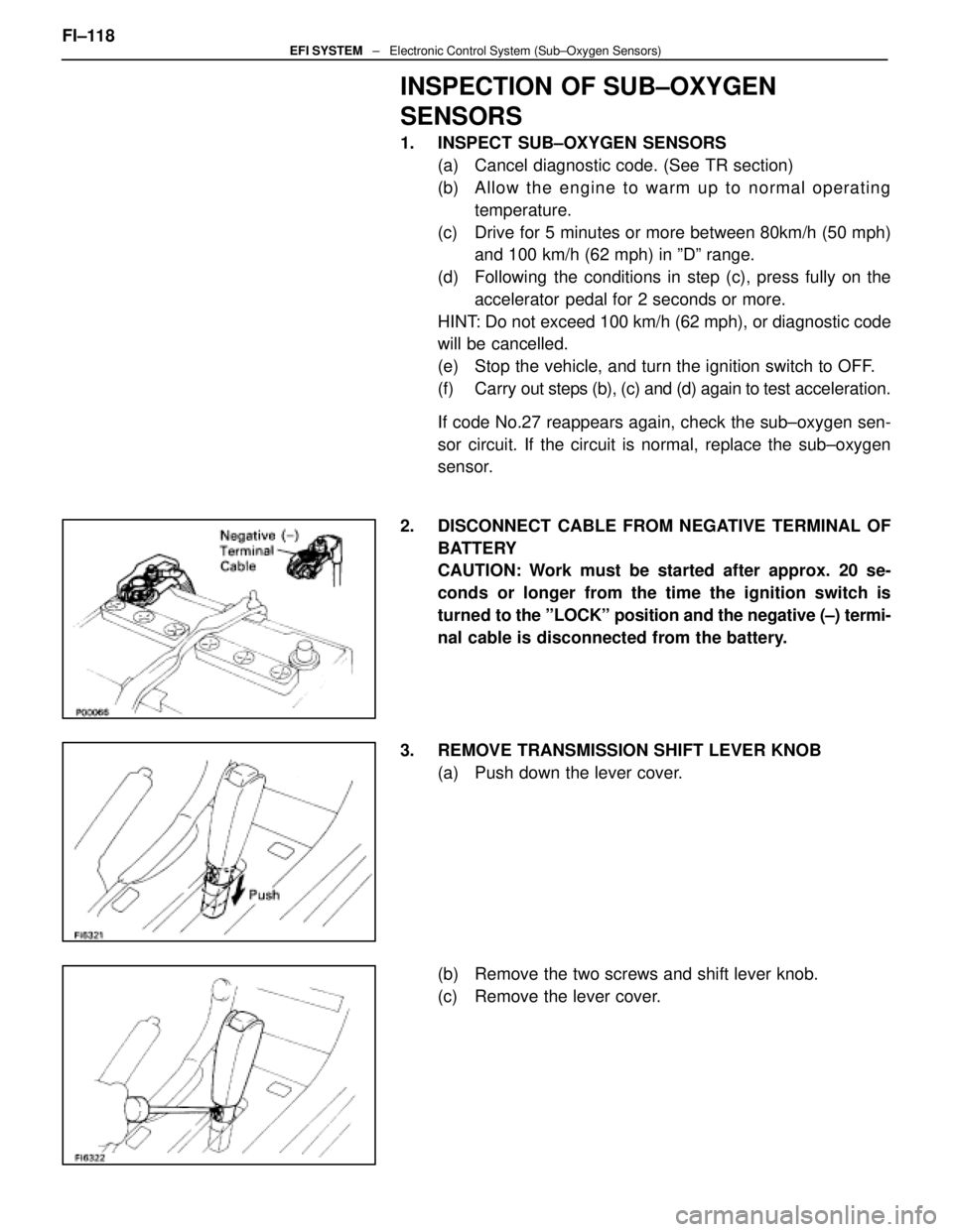
INSPECTION OF SUB±OXYGEN
SENSORS
1. INSPECT SUB±OXYGEN SENSORS(a) Cancel diagnostic code. (See TR section)
(b) A llo w th e en g in e to wa rm up to no rma l op e ra tin gtemperature.
(c) Drive for 5 minutes or more between 80km/h (50 mph) and 100 km/h (62 mph) in ºDº range.
(d) Following the conditions in step (c), press fully on the accelerator pedal for 2 seconds or more.
HINT: Do not exceed 100 km/h (62 mph), or diagnostic code
will be cancelled.
(e) Stop the vehicle, and turn the ignition switch to OFF.
(f) Carry out steps (b), (c) and (d) again to test acceleration.
If code No.27 reappears again, check the sub±oxygen sen-
sor circuit. If the circuit is normal, replace the sub±oxygen
sensor.
2. DISCONNECT CABLE FROM NEGATIVE TERMINAL OF BATTERY
CAUTION: Work must be started after approx. 20 se-
conds or longer from the time the ignition switch is
turned to the ºLOCKº position and the negative (±) termi-
nal cable is disconnected from the battery.
3. REMOVE TRANSMISSION SHIFT LEVER KNOB (a) Push down the lever cover.
(b) Remove the two screws and shift lever knob.
(c) Remove the lever cover.
FI±118
EFI SYSTEM
± Electronic Control System (Sub±Oxygen Sensors)
WhereEverybodyKnowsYourName
Page 1983 of 4087

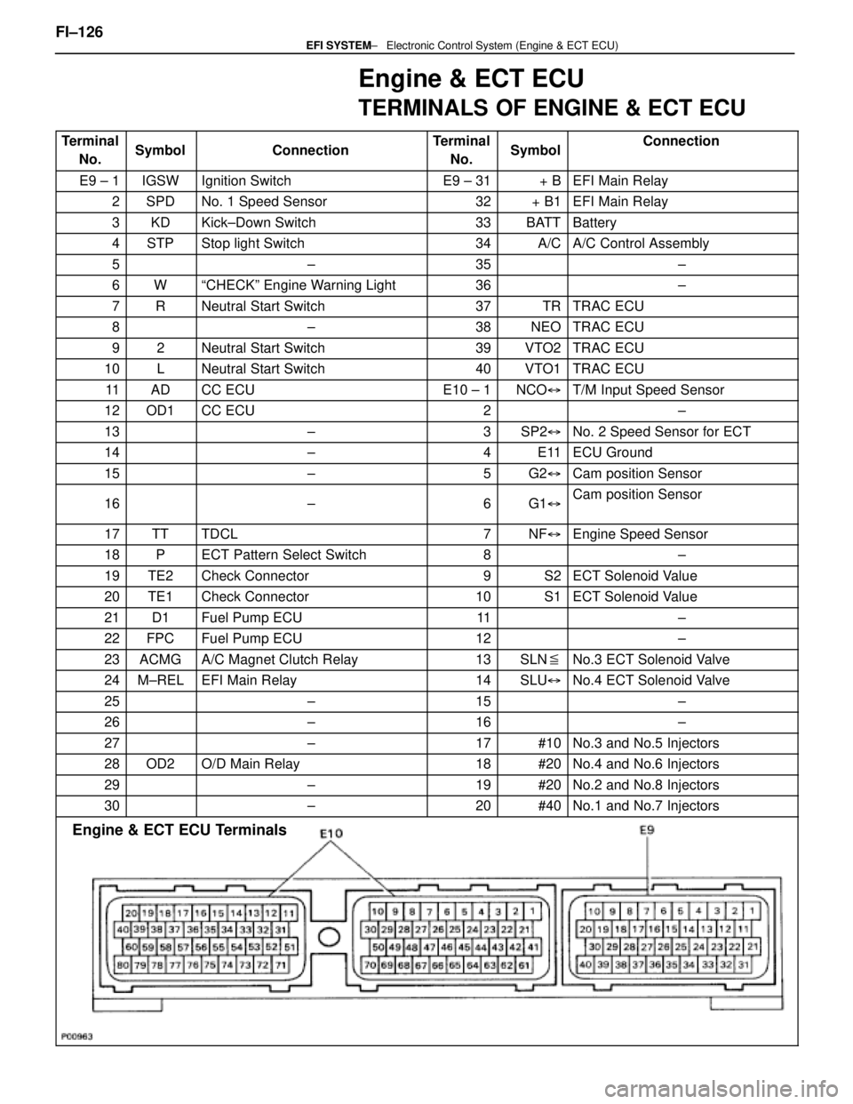
Engine & ECT ECU
TERMINALS OF ENGINE & ECT ECU
TerminalNo.SymbolConnectionTerminalNo.SymbolConnection
E9 ± 1IGSWIgnition SwitchE9 ± 31+ BEFI Main Relay
2SPDNo. 1 Speed Sensor32+ B1EFI Main Relay
3KDKick±Down Switch33BATTBattery
4STPStop light Switch34A/CA/C Control Assembly
5±35±
6WªCHECKº Engine Warning Light36±
7RNeutral Start Switch37TRTRAC ECU
8±38NEOTRAC ECU
92Neutral Start Switch39VTO2TRAC ECU
10LNeutral Start Switch40VTO1TRAC ECU
11ADCC ECUE10 ± 1NCO �T/M Input Speed Sensor
12OD1CC ECU2±
13±3SP2�No. 2 Speed Sensor for ECT
14±4E11ECU Ground
15±5G2�Cam position Sensor
16±6G1�Cam position Sensor
17TTTDCL7NF�Engine Speed Sensor
18PECT Pattern Select Switch8±
19TE2Check Connector9S2ECT Solenoid Value
20TE1Check Connector10S1ECT Solenoid Value
21D1Fuel Pump ECU11±
22FPCFuel Pump ECU12±
23ACMGA/C Magnet Clutch Relay13SLN �No.3 ECT Solenoid Valve
24M±RELEFI Main Relay14SLU�No.4 ECT Solenoid Valve
25±15±
26±16±
27±17#10No.3 and No.5 Injectors
28OD2O/D Main Relay18#20No.4 and No.6 Injectors
29±19#20No.2 and No.8 Injectors
30±20#40No.1 and No.7 Injectors
Engine & ECT ECU Terminals
FI±126 ± Electronic Control \
System (Engine & ECT ECU)EFI SYSTEM
WhereEverybodyKnowsYourName
Page 1994 of 4087

SERVICE SPECIFICATIONS
SERVICE DATA
Fuel pumpResistance0.2 ± 3.0 �
Cold start
injectorResistance
Fuel leakage2 ± 4 �
One drop or less per minute
Fuel pressure
regulatorFuel pressureat no vacuum265 ± 304 kPa
(2.7 ± 3.1 kgf/cm2, 38 ± 44 psi)
InjectorResistance
Injection volume
Difference between each cylinder
Fuel leakage13.4 ± 14.2 �
55 ± 70 cc (3.4 ± 4.3 cu in.) per 15 sec.
10 cc (0.6 cu in.) or less
One drop or less per minute
Air flow meterResistance (THA ± E2)at±20 °C (±4 °F)
at 0 °C (32 °F)
at 20 °C (68 °F)
at 40 °C (104 °F)
at 60 °C (140 °F)
at 80 °C (176 °F)10 ± 20 k �
4 ± 7 k �
2 ± 7 k �
0.9 ± 1.3 k �
0.4 ± 0.7 k �
0.2 ± 0.4 k �
Throttle bodyThrottle body fully closed angle6°
Throttle
positionClearance between
stop screw and leverBetween terminalsResistance
sensor
(main)0 mm
0.40 mm
0.65 mm0 in.
0.016 in.
0.026 in.VTA1 ± E2 IDL1 ± E2
IDL1 ± E2
VTA1 E2
0.2 ± 0.8 k �
2.3 k � or less
Infinity
33 100k �Throttle valve fully opened position
±VTA1 ± E2VC ± E2
y
3.3 ± 10.0 k �
4.0 ± 9.0 k �
Sub±throttle
positionClearance between
stop screw and leverBetween terminalsResistance
sensor
(w/ TRAC)0 mm
0.30 mm
0.50 mm0 in.
0.012 in.
0.020 in.VTA2 ± E2 IDL2 ± E2
IDL2 ± E2
VTA2 E2
0.2 ± 0.8 k �
2.3 k � or less
Infinity
33 100k �Throttle valve fully opened position
±VTA2 ± E2VC ± E2
y
3.3 ± 10.0 k �
4.0 ± 9.0 k �
Sub±throttle
actuator
(w/ TRAC)Resistance (ACM ± A and A, BCM ± B and B)0.5 ± 1.0 �
ISC valveResistance (B1 ± S1 and S3, B2 ± S2 and S4)10 ± 30 �
Cold start
injector time
switchResistance STA ± STJ below 15 °C (59 °F)
above 30 °C (86 °F)
STA ± Ground25 ± 45 �
65 ± 85
25 ± 85 �
VSV for fuel
pressure
controlResistance37 ± 44 �
FI±137 ± Service SpecificationsEFI SYSTEM
WhereEverybodyKnowsYourName
Page 2021 of 4087

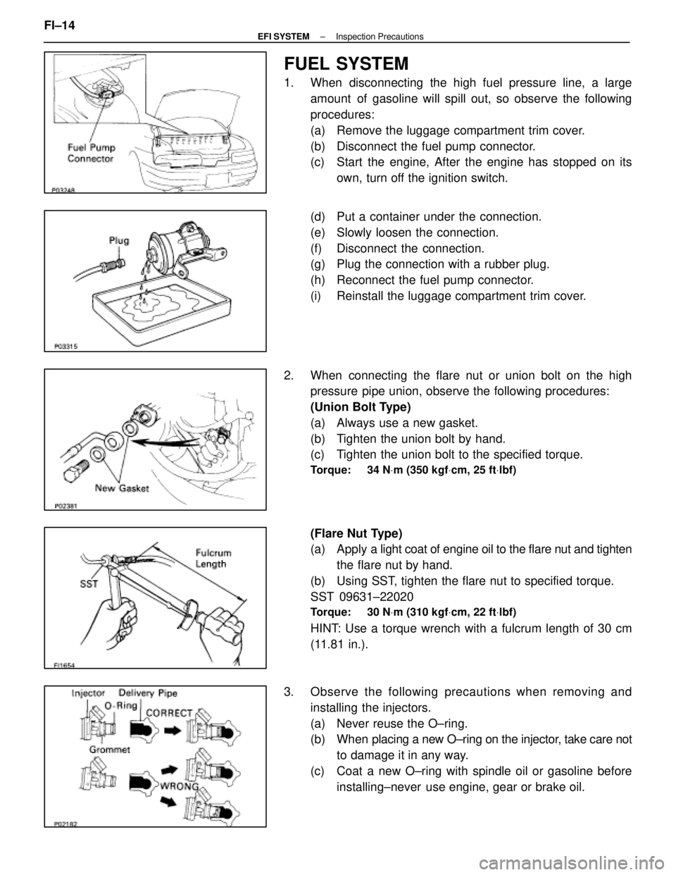
FUEL SYSTEM
1. When disconnecting the high fuel pressure line, a largeamount of gasoline will spill out, so observe the following
procedures:
(a) Remove the luggage compartment trim cover.
(b) Disconnect the fuel pump connector.
(c) Start the engine, After the engine has stopped on itsown, turn off the ignition switch.
(d) Put a container under the connection.
(e) Slowly loosen the connection.
(f) Disconnect the connection.
(g) Plug the connection with a rubber plug.
(h) Reconnect the fuel pump connector.
(i) Reinstall the luggage compartment trim cover.
2. When connecting the flare nut or union bolt on the high pressure pipe union, observe the following procedures:
(Union Bolt Type)
(a) Always use a new gasket.
(b) Tighten the union bolt by hand.
(c) Tighten the union bolt to the specified torque.
Torque: 34 N Vm (350 kgf Vcm, 25 ft Vlbf)
(Flare Nut Type)
(a) Apply a light coat of engine oil to the flare nut and tighten
the flare nut by hand.
(b) Using SST, tighten the flare nut to specified torque.
SST 09631±22020
Torque: 30 N Vm (310 kgf Vcm, 22 ft Vlbf)
HINT: Use a torque wrench with a fulcrum length of 30 cm
(11.81 in.).
3. Observe the following precautions when removing and installing the injectors.
(a) Never reuse the O±ring.
(b) When placing a new O±ring on the injector, take care not
to damage it in any way.
(c) Coat a new O±ring with spindle oil or gasoline before installing±never use engine, gear or brake oil.
FI±14
±
EFI SYSTEM Inspection Precautions
WhereEverybodyKnowsYourName
Page 2030 of 4087

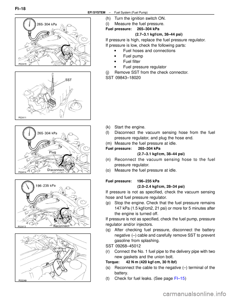
(h) Turn the ignition switch ON.
(i) Measure the fuel pressure.
Fuel pressure: 265±304 kPa (2.7±3.1 kgf/cm, 38±44 psi)
If pressure is high, replace the fuel pressure regulator.
If pressure is low, check the following parts:w Fuel hoses and connections
w Fuel pump
w Fuel filter
w Fuel pressure regulator
(j) Remove SST from the check connector.
SST 09843±18020
(k) Start the engine.
(l) Disconnect the vacuum sensing hose from the fuel pressure regulator, and plug the hose end.
(m) Measure the fuel pressure at idle.
Fuel pressure: 265±304 kPa
(2.7±3.1 kgf/cm, 38±44 psi)
(n) Re c onnect the vacuum sensing hose to the fuel
pressure regulator.
(o) Measure the fuel pressure at idle.
Fuel pressure: 196±235 kPa
(2.0±2.4 kgf/cm, 28±34 psi)
If pressure is not as specified, check the vacuum sensing
hose and fuel pressure regulator.
(p) Stop the engine. Check that the fuel pressure remains147 kPa (1.5 kgf/cm2, 21 psi) or more for 5 minutes after
the engine is turned off.
If pressure is not as specified, check the fuel pump, pressure
regulator and/or injectors.
(q) After checking fuel pressure, disconnect the battery
negative (±) cable and carefully remove SST to prevent
gasoline from splashing.
SST 09268±45012
(r) Connect the No. 1 fuel pipe to the delivery pipe with two new gaskets and the union bolt.
Torque: 42 N Vm (420 kgf Vcm, 30 ft Vlbf)
(s) Reconnect the cable to the negative (±) terminal of the
battery.
(t) Check for fuel leaks. (See page FI±15)
FI±18
±
EFI SYSTEM Fuel System (Fuel Pump)
WhereEverybodyKnowsYourName