Page 1269 of 4087
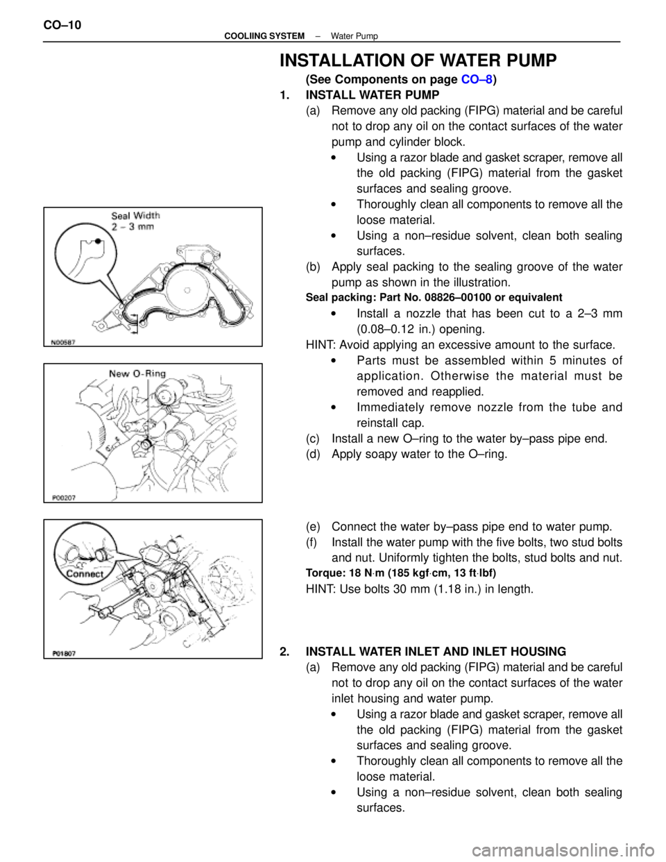
INSTALLATION OF WATER PUMP
(See Components on page CO±8)
1. INSTALL WATER PUMP (a) Remove any old packing (FIPG) material and be careful
not to drop any oil on the contact surfaces of the water
pump and cylinder block.
w Using a razor blade and gasket scraper, remove all
the old packing (FIPG) material from the gasket
surfaces and sealing groove.
w Thoroughly clean all components to remove all the
loose material.
w Using a non±residue solvent, clean both sealing
surfaces.
(b) Apply seal packing to the sealing groove of the water pump as shown in the illustration.
Seal packing: Part No. 08826±00100 or equivalent
w Install a nozzle that has been cut to a 2±3 mm
(0.08±0.12 in.) opening.
HINT: Avoid applying an excessive amount to the surface. w Parts must be assembled within 5 minutes of
application. Otherwise the material must be
removed and reapplied.
w Immediately remove nozzle from the tube and
reinstall cap.
(c) Install a new O±ring to the water by±pass pipe end.
(d) Apply soapy water to the O±ring.
(e) Connect the water by±pass pipe end to water pump.
(f) Install the water pump with the five bolts, two stud bolts and nut. Uniformly tighten the bolts, stud bolts and nut.
Torque: 18 N Vm (185 kgf Vcm, 13 ft Vlbf)
HINT: Use bolts 30 mm (1.18 in.) in length.
2. INSTALL WATER INLET AND INLET HOUSING (a) Remove any old packing (FIPG) material and be careful
not to drop any oil on the contact surfaces of the water
inlet housing and water pump.
w Using a razor blade and gasket scraper, remove all
the old packing (FIPG) material from the gasket
surfaces and sealing groove.
w Thoroughly clean all components to remove all the
loose material.
w Using a non±residue solvent, clean both sealing
surfaces.
CO±10
±
COOLIING SYSTEM Water Pump
WhereEverybodyKnowsYourName
Page 1270 of 4087
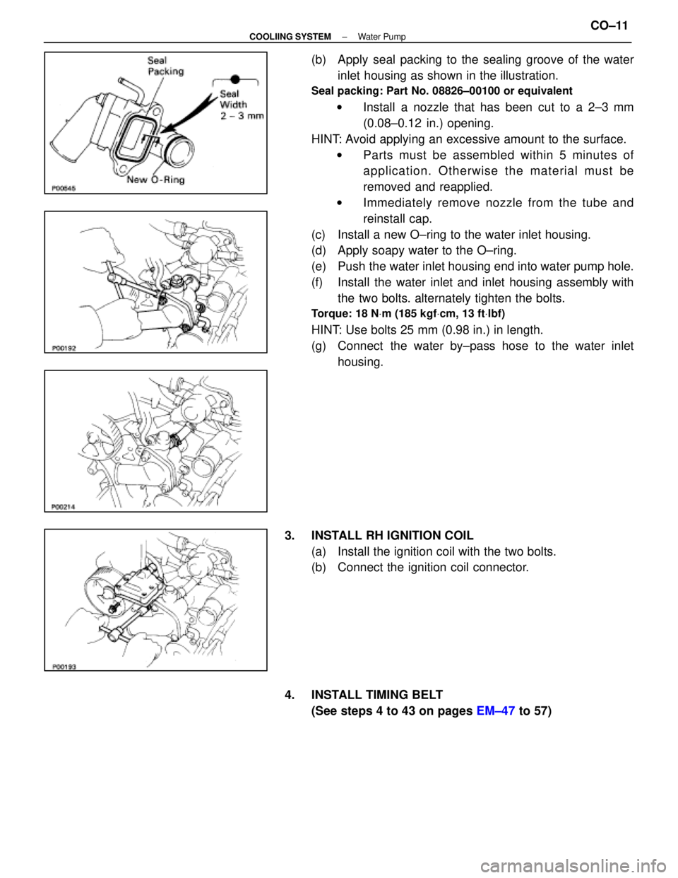
(b) Apply seal packing to the sealing groove of the waterinlet housing as shown in the illustration.
Seal packing: Part No. 08826±00100 or equivalent
w Install a nozzle that has been cut to a 2±3 mm
(0.08±0.12 in.) opening.
HINT: Avoid applying an excessive amount to the surface. w Parts must be assembled within 5 minutes of
application. Otherwise the material must be
removed and reapplied.
w Immediately remove nozzle from the tube and
reinstall cap.
(c) Install a new O±ring to the water inlet housing.
(d) Apply soapy water to the O±ring.
(e) Push the water inlet housing end into water pump hole.
(f) Install the water inlet and inlet housing assembly with the two bolts. alternately tighten the bolts.
Torque: 18 N Vm (185 kgf Vcm, 13 ft Vlbf)
HINT: Use bolts 25 mm (0.98 in.) in length.
(g) Connect the water by±pass hose to the water inlet
housing.
3. INSTALL RH IGNITION COIL (a) Install the ignition coil with the two bolts.
(b) Connect the ignition coil connector.
4. INSTALL TIMING BELT (See steps 4 to 43 on pages EM±47 to 57)
±
COOLIING SYSTEM Water PumpCO±11
WhereEverybodyKnowsYourName
Page 1271 of 4087
THERMOSTAT
HINT: Removing the thermostat would decrease the cooling
efficiency. Do not remove the thermostat, even if it tends to
overheat.
COMPONENTS
REMOVAL OF THERMOSTAT
1. DRAIN ENGINE COOLANT (See page CO±5)
2. REMOVE THERMOSTAT (a) Remove the two nuts holding the water inlet to the water
pump, and disconnect the water inlet from the water
pump.
(b) Remove the thermostat.
(c) Remove the gasket from the thermostat.
CO±10
±
COOLING SYSTEM Thermostat
WhereEverybodyKnowsYourName
Page 1275 of 4087
RADIATOR
CLEANING OF RADIATOR
Using water or a steam cleaner, remove any mud and dirt
from the radiator core.
NOTICE: If using a high pressure type cleaner, be careful
not to deform the fins of the radiator core. If the cleaner
nozzle pressure is 2,942±3,432 kPa (30±35 kgf/cm2,
427±498 psi), keep a distance at least 40±50 cm
(15.75±19.69 in.) between the radiator core and cleaner
nozzle.
INSPECTION OF RADIATOR
1. REMOVE RADIATOR CAP FROM RESERVOIR TANK
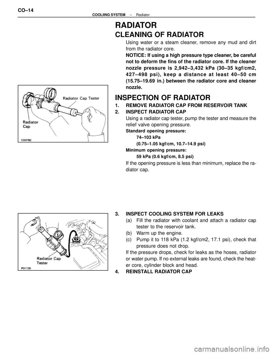
2. INSPECT RADIATOR CAPUsing a radiator cap tester, pump the tester and measure the
relief valve opening pressure.
Standard opening pressure:
74±103 kPa
(0.75±1.05 kgf/cm, 10.7±14.9 psi)
Minimum opening pressure:
59 kPa (0.6 kgf/cm, 8.5 psi)
If the opening pressure is less than minimum, replace the ra-
diator cap.
3. INSPECT COOLING SYSTEM FOR LEAKS (a) Fill the radiator with coolant and attach a radiator captester to the reservoir tank.
(b) Warm up the engine.
(c) Pump it to 118 kPa (1.2 kgf/cm2, 17.1 psi), check that pressure does not drop.
If the pressure drops, check for leaks as the hoses, radiator
or water pump. If no external leaks are found, check the heat-
er core, cylinder block and head.
4. REINSTALL RADIATOR CAP
CO±14
±
COOLIING SYSTEM Radiator
WhereEverybodyKnowsYourName
Page 1283 of 4087
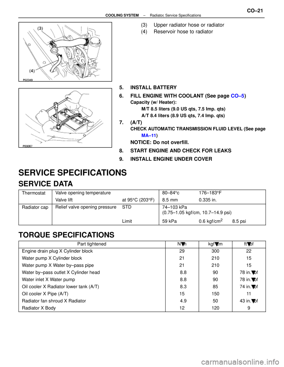
(3) Upper radiator hose or radiator
(4) Reservoir hose to radiator
5. INSTALL BATTERY
6. FILL ENGINE WITH COOLANT (See page CO±5)
Capacity (w/ Heater):
M/T 8.5 liters (9.0 US qts, 7.5 Imp. qts)
A/T 8.4 liters (8.9 US qts, 7.4 Imp. qts)
7. (A/T)
CHECK AUTOMATIC TRANSMISSION FLUID LEVEL (See pageMA±11 )
NOTICE: Do not overfill.
8. START ENGINE AND CHECK FOR LEAKS
9. INSTALL ENGINE UNDER COVER
SERVICE SPECIFICATIONS
SERVICE DATA
ThermostatValve opening temperature80±84 5c176±183 5F
Valve liftat 95 5C (203 5F) 8.5 mm0.335 in.
Radiator capRelief valve opening pressureSTD74±103 kPa
(0 75 1 05 k f/ 10 7 14 9 i)(0.75±1.05 kgf/cm, 10.7±14.9 psi)
Limit59 kPa0.6 kgf/cm28.5 psi
TORQUE SPECIFICATIONS
Part tightenedN �mkgf �cmft �lbf
Engine drain plug X Cylinder block2930022
Water pump X Cylinder block2121015
Water pump X Water by±pass pipe2121015
Water by±pass outlet X Cylinder head 8.89078 in. �lbf
Water inlet X Water pump 8.89078 in. �lbf
Oil cooler X Radiator lower tank (A/T) 8.38574 in. �lbf
Oil cooler X Pipe (A/T)1515011
Radiator fan shroud X Radiator 4.95043 in. �lbf
Radiator X Body121209
±
COOLING SYSTEM Radiator, Service SpecificationsCO±21
WhereEverybodyKnowsYourName
Page 1284 of 4087
ELECTRONICALLY CONTROLLED HYDRAULIC COOLING FAN
Description
In this way system, the cooling fan ECU controls the hydraulic pressure ac\
ting on the hydraulic motor, thus
controlling the speed of the cooling fan steplessly in response to the c\
ondition of the engine and air conditioner.
Operation
The hydraulic pump is driven by a drive belt (V±ribbed belt). The sole\
noid valve adjusts the volume of oil
sent from the hydraulic pump to the hydraulic motor which drives the fan dir\
ectly, thereby controlling the fan
speed. Oil which has passed through the hydraulic motor is cooled by the oil coole\
r before returning to the reservoir
tank. The solenoid valve is controlled by the computer in accordance with the E/G\
rpm, water temp. and A/C
signals. CO±22
±
COOLIING SYSTEM Electronically Controlled Hydraulic
Cooling Fan (Description, Operation)
WhereEverybodyKnowsYourName
Page 1291 of 4087
10. REMOVE LH ENGINE WIRE COVERRemove the two bolts and engine wire cover.
11. REMOVE VSV FOR EVAP SYSTEM Remove the two bolts, and disconnect the VSV from cylinder
head and timing belt cover.
12. REMOVE RH NO.3 TIMING BELT COVER Remove the three bolts and timing belt cover.
13. REMOVE LH NO.3 TIMING BELT COVER (a) Remove the four mounting bolts.
(b) Disconnect the cord grommet from the timing belt cover,
and remove the timing belt cover.
(c) Remove the cord grommet from the high±tension cord.
14. DISCONNECT RADIATOR HOSE FROM WATER INLET
15. REMOVE DRIVE BELT IDLER PULLEY Remove the pulley bolt, cover plate and idler pulley.
±
COOLIING SYSTEM Electronically Controlled Hydraulic
Cooling Fan (Hydraulic Pump)CO±29
WhereEverybodyKnowsYourName
Page 1305 of 4087
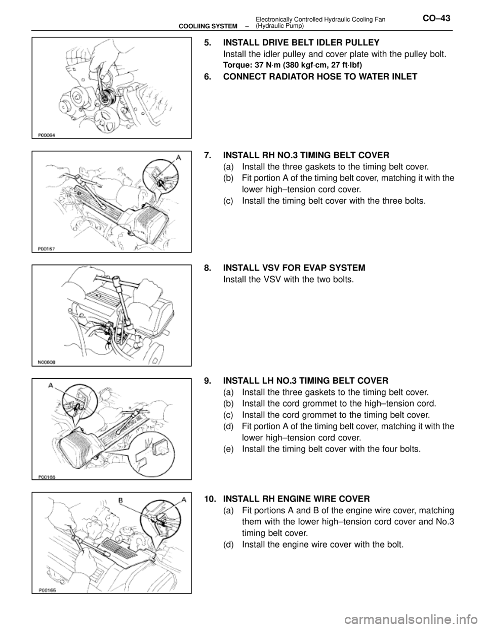
5. INSTALL DRIVE BELT IDLER PULLEYInstall the idler pulley and cover plate with the pulley bolt.
Torque: 37 N Vm (380 kgf Vcm, 27 ft Vlbf)
6. CONNECT RADIATOR HOSE TO WATER INLET
7. INSTALL RH NO.3 TIMING BELT COVER
(a) Install the three gaskets to the timing belt cover.
(b) Fit portion A of the timing belt cover, matching it with the
lower high±tension cord cover.
(c) Install the timing belt cover with the three bolts.
8. INSTALL VSV FOR EVAP SYSTEM Install the VSV with the two bolts.
9. INSTALL LH NO.3 TIMING BELT COVER (a) Install the three gaskets to the timing belt cover.
(b) Install the cord grommet to the high±tension cord.
(c) Install the cord grommet to the timing belt cover.
(d) Fit portion A of the timing belt cover, matching it with the
lower high±tension cord cover.
(e) Install the timing belt cover with the four bolts.
10. INSTALL RH ENGINE WIRE COVER (a) Fit portions A and B of the engine wire cover, matchingthem with the lower high±tension cord cover and No.3
timing belt cover.
(d) Install the engine wire cover with the bolt.
±
COOLIING SYSTEM Electronically Controlled Hydraulic Cooling Fan
(Hydraulic Pump)CO±43
WhereEverybodyKnowsYourName