Page 3725 of 4087
INSPECTION PROCEDURE
Check output condition of diag. code 43
Setting the test mode.
6. Turn ignition switch OFF.
7. Connect terminals TE2 and E1 of TDCL.
8. Turn ignition switch ON.(Don't start the engine)
9. Connect terminals TE1 and E1 of TDCL.
Check if code ª43º is output by the ªCHECKº en-
gine warning light.
Code ª43º is output.
Start the engine.
Check if the code ª43º disappear.
Code ª43º is not output.
Proceed to next circuit inspection shown on
matrix chart (See page
TR±39).
Check for open in harness and connector between engine (& ECT) ECU
and starter relay (See page IN±27)
Repair or replace harness or connector.
Check and replace engine (& ECT) ECU.
±
ENGINE TROUBLESHOOTING Circuit InspectionTR±97
WhereEverybodyKnowsYourName
Page 3729 of 4087
NGOK
OKNG
v
INSPECTION PROCEDURE
1Check output condition of diag. code 43.
C
OK
P
OK
C
Setting the test mode.
(2) Turn ignition switch OFF.
(2) Connect terminals TE2 and E1 of TDCL.
(2) Turn ignition switch ON.(Don't start the engine)
(2) Connect terminals TE1 and E1 of TDCL.
Check if code ª43º is output by the ªCHECKº engine
warning light.
Code ª43º is output.
Start the engine.
Check if the code ª43º disapears.
Code ª43º is not output.
Proceed to next circuit inspection shown on maxtric
chart (See page TR±35).
2Check for open in harness and connectors between engine & ECT ECU and st\
arter relay
(See page IN±27).
Repair or replace harness or connector.
Check and replace engine & ECT ECU.
±
ENGINE TROUBLESHOOTING Circuit InspectionTR±101
WhereEverybodyKnowsYourName
Page 3731 of 4087
CIRCUIT DESCRIPTION (Cont'd)
DIAGNOSIS CODE DETECTION DRIVING PATTERN
Purpose of the driving pattern.
(a) To simulate diag. code detecting condition after diag. code is recorded.
(b) To check that the malfunction is corrected when the repair is completed c\
onfirming that diag. code is nolonger detected.
Malfunction: Open or Short in Knock Sensor
�Start engine and warm up.
�After engine is warmed up, let it idle for 3 min.
�With the A/C ON, perform quick racing (5,000 rpm) three times.
(Rapidly depress the accelerator pedal and suddenly release it.)
HINT: If a malfunction exists, the ºCHECKº engine warning light will lig\
ht up when sudden racing is performed.
NOTICE: If the conditions in this test are not strictly followed, detection of t\
he malfunction will
not be possible.
±
ENGINE TROUBLESHOOTING Circuit InspectionTR±103
WhereEverybodyKnowsYourName
Page 3737 of 4087

CIRCUIT DESCRIPTION (Cont'd)
DIAGNOSIS TROUBLE CODE DETECTION DRIVING PATTERN
Purpose of the driving pattern.
(a) To simulate diag. trouble code detecting condition after diag. trouble co\
de is recorded.
(b) To check that the malfunction is corrected when the repair is completed co\
nfirming that diag. trouble codeis no longer detected.
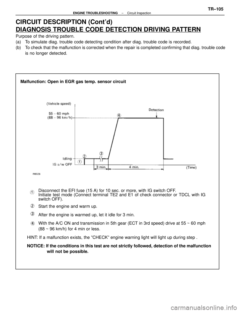
Malfunction: Open in EGR gas temp. sensor circuit
Disconnect the EFI fuse (15 A) for 10 sec. or more, with IG switch OFF\
.
Initiate test mode (Connect terminal TE2 and E1 of check connector or TDCL with\
IG
switch OFF).
Start the engine and warm up.
After the engine is warmed up, let it idle for 3 min.
With the A/C ON and transmission in 5th gear (ECT in 3rd speed) drive at 5\
5 ~ 60 mph
(88 ~ 96 km/h) for 4 min or less.
HINT: If a malfunction exists, the ºCHECKº engine warning light will l\
ight up during step .
NOTICE: If the conditions in this test are not strictly followed, detection of \
the malfunction will not be possible.
±
ENGINE TROUBLESHOOTING Circuit InspectionTR±105
WhereEverybodyKnowsYourName
Page 3743 of 4087
CIRCUIT DESCRIPTION (Cont'd)
DIAGNOSIS CODE DETECTION DRIVING PATTERN
Purpose of the driving pattern.
(a) To simulate diag. code detecting condition after diag. code is recorded.
(b) To check that the malfunction is corrected when the repair is completed c\
onfirming that diag. code is nolonger detected.
�Initiate test mode (See page TR±12).
�Start engine and warm up.
�After engine is warmed up, let it idle for 3 min.
�With the A/C ON and transmission in D range (O/D OFF), drive at 40±\
70 mph for 4 min.
HINT: If a malfunction exists, the ºCHECKº engine warning light will light up at 1±4 min. of driving at 40±70 mph (64±112 km/h).
NOTICE: If the conditions in this test are not strictly followed, detection of the\
malfunction will not be possible.
Malfunction: Open in EGR gas temp. sensor circuit
±
ENGINE TROUBLESHOOTING Circuit InspectionTR±109
WhereEverybodyKnowsYourName
Page 3758 of 4087

OKNG
OKNG
INSPECTION PROCEDURE
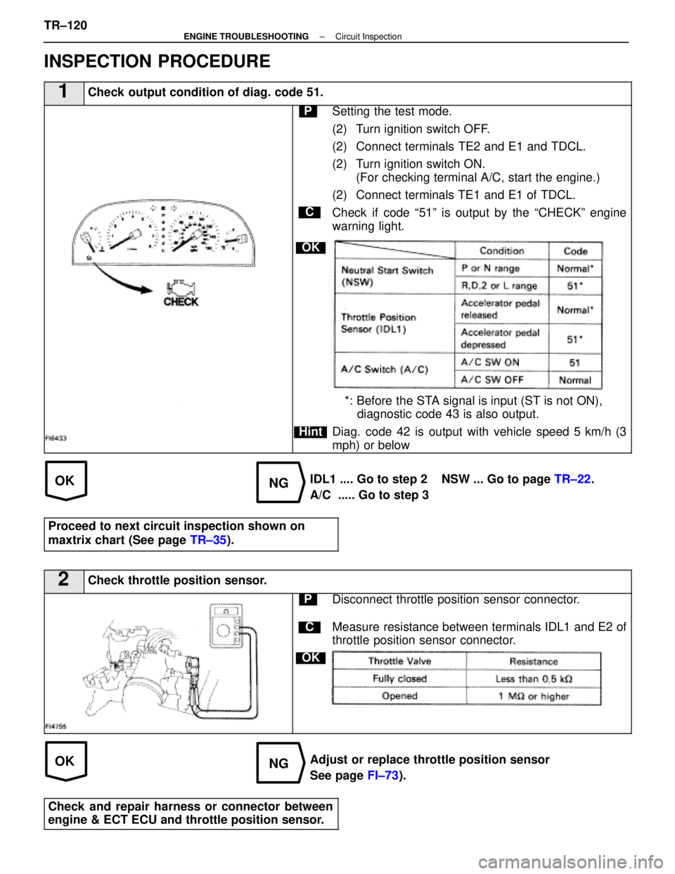
1Check output condition of diag. code 51.
C
OK
Hint
PSetting the test mode.
(2) Turn ignition switch OFF.
(2) Connect terminals TE2 and E1 and TDCL.
(2) Turn ignition switch ON.(For checking terminal A/C, start the engine.)
(2) Connect terminals TE1 and E1 of TDCL.
Check if code ª51º is output by the ªCHECKº engine
warning light.
*: Before the STA signal is input (ST is not ON), diagnostic code 43 is also output.
Diag. code 42 is output with vehicle speed 5 km/h (3
mph) or below
IDL1 .... Go to step 2 NSW ... Go to page TR±22.
A/C ..... Go to step 3
Proceed to next circuit inspection shown on
maxtrix chart (See page TR±35).
2Check throttle position sensor.
C
OK
PDisconnect throttle position sensor connector.
Measure resistance between terminals IDL1 and E2 of
throttle position sensor connector.
Adjust or replace throttle position sensor
See page FI±73).
Check and repair harness or connector between
engine & ECT ECU and throttle position sensor.
TR±120±
ENGINE TROUBLESHOOTING Circuit Inspection
WhereEverybodyKnowsYourName
Page 3868 of 4087

26
ELECTRICAL WIRING ROUTING
Position of Parts in Engine Compartment
A 1 A/C Ambient Temp. Sensor E 1 ECT Solenoid
A 2 A/C Lock Sensor and A/C Magnetic Clutch E 2 EFI Water Temp. Sensor
A 3 A/C High Pressure SW E 3 EGR Gas Temp. Sensor (for USA Spec.)
A 4 ABS Actuator E 5 Engine Hood Courtesy SW
A 5 ABS Actuator (w/ Traction Control) E 6 Engine Oil Level Warning SW
A 6 ABS Actuator (w/ Traction Control)
A 7 ABS Speed Sensor Front LH F 1 Front Airbag Sensor LH
A 8 ABS Speed Sensor Front RH F 2 Front Airbag Sensor RH
A 9 Air Flow Meter F 3 Front Clearance Light LH
A 10 Alternator F 4 Front Clearance Light RH
A 11 Alternator F 5Front Side Marker Light LH
A 33 ABS Actuator (w/o Traction Control) F 6 Front Side Marker Light RH F 7 Front Turn Signal Light LH
B 1 Brake Fluid Level SW F 8 Front Turn Signal Light RH
B 6 Back±Up Light SW (for M/T) F 9 Fuse Block
C 3 Check Connector H 1 Headlight Hi LH
C 6 Cornering Light LH H 2 Headlight Hi RH
C 7 Cornering Light RH H 3 Headlight Lo LH
C 8 Cruise Control Actuator H 4 Headlight Lo RH H 5 Horn LH
D 13 Distributor H 6 Horn RH
WhereEverybodyKnowsYourName
Page 3902 of 4087

67
2. CONTROL SYSTEM
*EFI (ELECTRONIC FUEL INJECTION) SYSTEM
THE EFI SYSTEM MONITORS THE ENGINE CONDITION THROUGH THE SIGNALS INPUT FROM EACH SENSOR (IN\
PUT SIGNALS
FROM (1) TO (13) ETC.) TO THE ECU. THE BEST FUEL INJECTION TIMING IS DECIDED BASED ON THIS DATA AND THE PROGRAM
MEMORIZED BY THE ECU, AND THE CONTROL SIGNAL IS OUTPUT TO TERMINALS #10, #20, #30, #40, #50 AND #60 OF THE ECU TO
OPERATE THE INJECTOR. (INJECT THE FUEL). THE EFI SYSTEM PRODUCES CONTROL OF FUEL INJECTION OPERATION BY THE
ECU IN RESPONSE TO THE DRIVING CONDITIONS.
* ESA (ELECTRONIC SPARK ADVANCE) SYSTEM
THE ESA SYSTEM MONITORS THE ENGINE CONDITION THROUGH THE SIGNALS INPUT TO THE ECU FROM EACH SENSOR (INPUT
SIGNALS FROM (1), (2), (4) TO (13) ETC.). THE BEST IGNITION TIMING IS DECIDED ACCORDING TO THIS DATA AND THE
MEMORIZED DATA IN THE ECU AND THE CONTROL SIGNAL IS OUTPUT TO TERMINAL IGT THIS SIGNAL CONTROLS THE IGNITER
TO PROVIDE THE BEST IGNITION TIMING FOR THE DRIVING CONDITIONS.
* OXYGEN SENSOR HEATER CONTROL SYSTEM (USA SPEC.)
THE OXYGEN SENSOR HEATER CONTROL SYSTEM TURNS THE HEATER ON WHEN THE INTAKE AIR VOLUME IS LOW (TEMP. OF
EXHAUST EMISSIONS IS LOW), AND WARMS UP THE OXYGEN SENSOR TO IMPROVE DETECTION PERFORMANCE OF THE
SENSOR.
THE ECU EVALUATES THE SIGNALS FROM EACH SENSOR (INPUT SIGNALS FROM (1), (2), (4)\
, (9) TO (11) ETC.,) AND OUTPUTS
CURRENT TO TERMINAL HT TO CONTROL THE HEATER.
* ISC (IDLE SPEED CONTROL) SYSTEM
THE ISC SYSTEM (STEP MOTOR TYPE) INCREASES THE RPM AND PROVIDES IDLING STABILITY FOR FAST IDLE±UP WHEN THE
ENGINE IS COLD, AND WHEN THE IDLE SPEED HAS DROPPED DUE TO ELECTRICAL LOAD AND SO ON. THE ECU EVALUATES
THE SIGNALS FROM EACH SENSOR (INPUT SIGNALS FROM (1), (4), (5), (8)\
, (9), (11) ETC.), OUTPUTS CURRENT TO TERMINAL ISC1,
ISC2, ISC3 AND ISC4 TO CONTROL ISC VALVE.
* EGR CONTROL SYSTEM
THE EGR CONTROL SYSTEM DETECTS THE SIGNAL FROM EACH SENSOR (INPUT SIGNALS \
FROM (1), (4), (9), (10) ETC.), AND
OUTPUTS CURRENT TO TERMINAL EGR TO CONTROL THE EGR VALVE.
* FUEL PUMP CONTROL SYSTEM
THE COMPUTER OUTPUTS CURRENT TO TERMINAL FPC AND CONTROLS THE FUEL PUMP ECU AND FUEL PUMP DRIVE SPEED
IN RESPONSE TO CONDITIONS.
* ACIS (ACOUSTIC CONTROL INDUCTION SYSTEM)
ACIS INCLUDES A VALVE IN THE BULKHEAD SEPARATING THE SURGE TANK INTO TWO PARTS. THIS VALE IS OPENED AND
CLOSED IN ACCORDANCE WITH THE DRIVING CONDITIONS TO CONTROL THE INTAKE MANIFOLD LENGTH IN TWO STAGES FOR
INCREASED ENGINE OUTPUT IN ALL RANGES FROM LOW TO HIGH SPEEDS.
THE ECU JUDGES THE VEHICLE SPEED BY THE SIGNALS ((4), (5)) FROM EACH \
SENSOR AND OUTPUTS SIGNALS TO THE
TERMINAL ACIS TO CONTROL THE VSV (FOR OPENING AND CLOSING THE INTAKE CONTROL VALVE).
3. DIAGNOSIS SYSTEM
WITH THE DIAGNOSIS SYSTEM, WHEN THERE IS A MALFUNCTION IN THE ECU SIGNAL\
SYSTEM, THE MALFUNCTIONING SYSTEM IS
RECORDED IN THE MEMORY. THE MALFUNCTIONING SYSTEM CAN BE FOUND BY READING THE CODE DISPLAYED BY THE
CHECKING ENGINE WARNING LIGHT.
4. FAIL±SAFE SYSTEM
WHEN A MALFUNCTION HAS OCCURRED IN ANY SYSTEM, IF THERE IS A POSSIBILITY OF \
ENGINE TROUBLE BEING CAUSED BY
CONTINUED CONTROL BASED ON THE SIGNALS FROM THAT SYSTEM, THE FAIL±SAFE SYSTEM EITHER CONTROLS THE SYSTEM
BY USING DATA (STANDARD VALUES) RECORDED IN THE ECU MEMORY OR ELSE STOPS THE ENGINE.
NOTE: THE SPECIFICATION DESCRIPTIONS ªUSA SPEC.º AND ªEXC. USA SPEC.º USED IN THIS SECTION INDICATE THE
FOLLOWING SPECIFICATIONS.
USA SPEC. : USA (50 STATES) SPECIFICATIONS
EXC. USA SPEC. : USA (EXCEPT CALIFORNIA) AND CANADIAN SPECIFICATIONS.
WhereEverybodyKnowsYourName