Page 597 of 4087

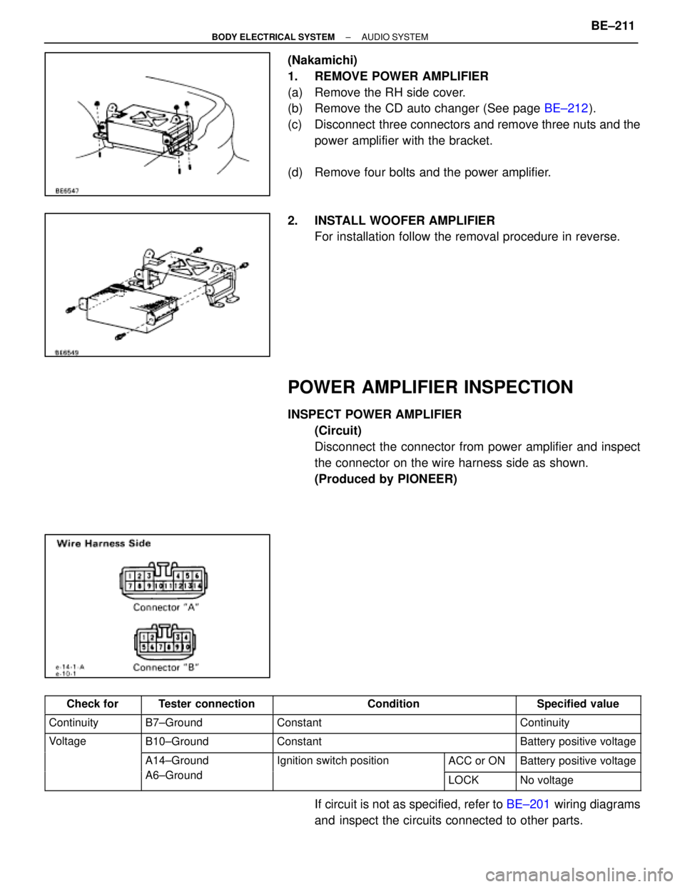
(Nakamichi)
1. REMOVE POWER AMPLIFIER
(a) Remove the RH side cover.
(b) Remove the CD auto changer (See page BE±212).
(c) Disconnect three connectors and remove three nuts and the power amplifier with the bracket.
(d) Remove four bolts and the power amplifier.
2. INSTALL WOOFER AMPLIFIER For installation follow the removal procedure in reverse.
POWER AMPLIFIER INSPECTION
INSPECT POWER AMPLIFIER
(Circuit)
Disconnect the connector from power amplifier and inspect
the connector on the wire harness side as shown.
(Produced by PIONEER)
������� �������Check for�������� ��������Tester connection��������������� ���������������Condition�������� ��������Specified value
������� �������Continuity�������� ��������B7±Ground��������������� ���������������Constant�������� ��������Continuity
������� �������Voltage�������� ��������B10±Ground��������������� ���������������Constant�������� ��������Battery positive voltage
������� ��������������� ��������A14±Ground
A6 G d
����������� �����������Ignition switch position����� �����ACC or ON�������� ��������Battery positive voltage������� ��������������� ��������A6±Ground����������� ���������������� �����LOCK�������� ��������No voltage
If circuit is not as specified, refer to BE±201 wiring diagrams
and inspect the circuits connected to other parts.
±
BODY ELECTRICAL SYSTEM AUDIO SYSTEMBE±211
WhereEverybodyKnowsYourName
Page 598 of 4087

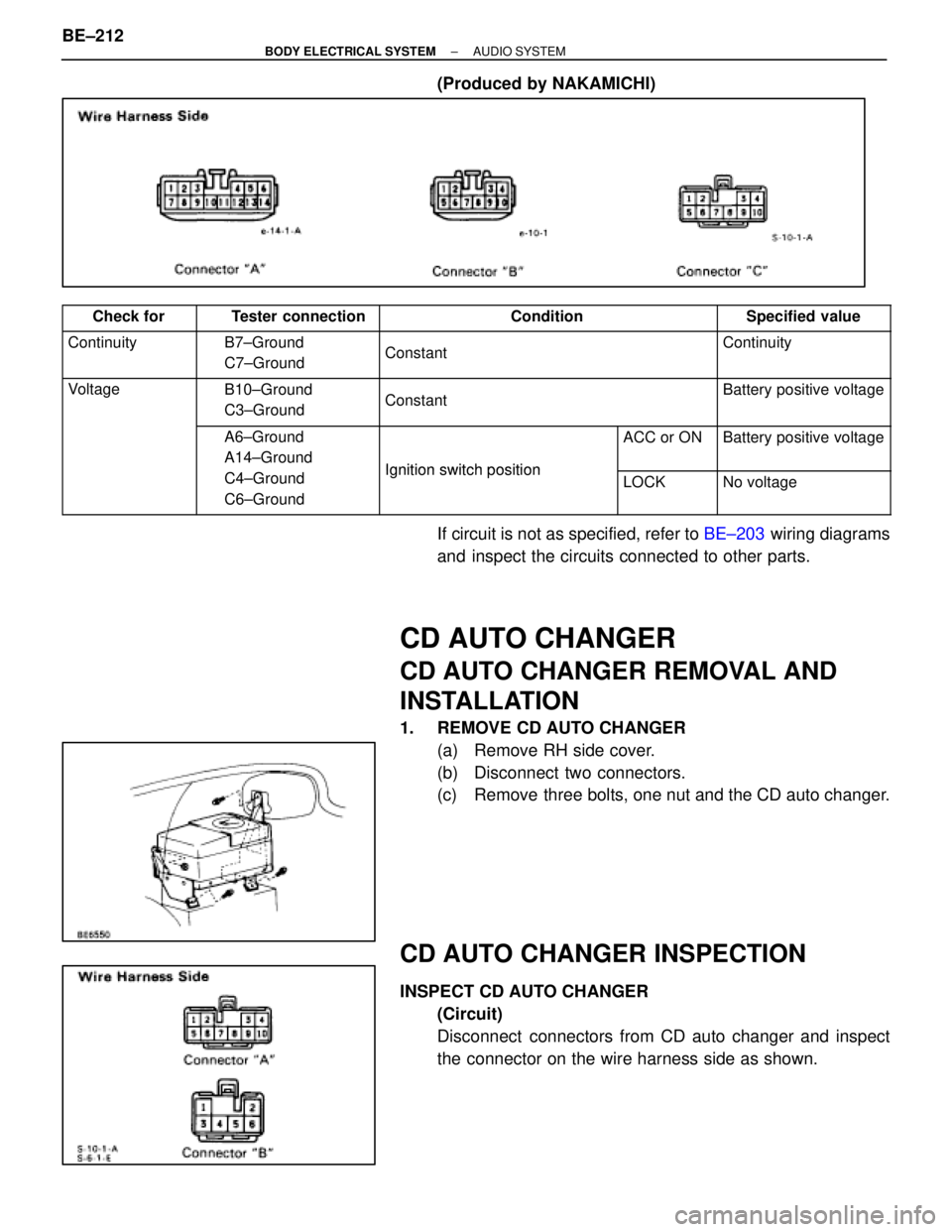
(Produced by NAKAMICHI)
������� �������Check for�������� ��������Tester connection��������������� ���������������Condition�������� ��������Specified value������� �
������
�������Continuity�������� �
�������
��������B7±Ground
C7±Ground��������������� �
��������������
���������������
Constant
��������
��������
��������Continuity
������� �
������
�������Voltage�������� �
�������
��������B10±Ground
C3±Ground��������������� �
��������������
���������������
Constant
��������
��������
��������Battery positive voltage
������� �
������
�������
�������� �
�������
��������A6±Ground
A14±Ground����������� �
����������
�����������
Ignition switchposition
����� �
����
�����
ACC or ON��������
��������
��������Battery positive voltage
������� �
������
�������
�������� �
�������
��������
C4±Ground
C6±Ground����������� �
����������
�����������
Ignition switch position����� �
����
�����
LOCK��������
��������
��������No voltage
If circuit is not as specified, refer to
BE±203 wiring diagrams
and inspect the circuits connected to other parts.
CD AUTO CHANGER
CD AUTO CHANGER REMOVAL AND
INSTALLATION
1. REMOVE CD AUTO CHANGER (a) Remove RH side cover.
(b) Disconnect two connectors.
(c) Remove three bolts, one nut and the CD auto changer.
CD AUTO CHANGER INSPECTION
INSPECT CD AUTO CHANGER(Circuit)
Disconnect connectors from CD auto changer and inspect
the connector on the wire harness side as shown.
BE±212
±
BODY ELECTRICAL SYSTEM AUDIO SYSTEM
WhereEverybodyKnowsYourName
Page 599 of 4087

������� �������
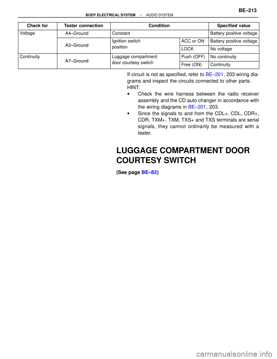
Check for�������� ��������Tester connection��������������� ���������������Condition�������� ��������Specified value
������� �������Voltage�������� ��������A4±Ground��������������� ���������������Constant�������� ��������Battery positive voltage
������� ��������������� ��������
A3±Ground
����������� �����������Ignition switch
iti
����� �����ACC or ON�������� ��������Battery positive voltage
������� ��������������� ��������A3±Ground����������� �����������position����� �����LOCK�������� ��������No voltage
������� �������Continuity�������� ��������
A7±Ground
����������� �����������Luggage compartment
d t it h
����� �����Push (OFF)�������� ��������No continuity������� ��������������� ��������A7±Ground����������� �����������door courtesy switch����� �����Free (ON)�������� ��������Continuity
If circuit is not as specified, refer to BE±201, 203 wiring dia-
grams and inspect the circuits connected to other parts.
HINT:
w Check the wire harness between the radio receiver
assembly and the CD auto changer in accordance with
the wiring diagrams in BE±201, 203.
w Since the signals to and from the CDL+, CDL, CDR+,
CDR, TXM+, TXM, TXS+ and TXS terminals are serial
signals, they cannot ordinarily be measured with a
tester.
LUGGAGE COMPARTMENT DOOR
COURTESY SWITCH
(See page BE±82)
±
BODY ELECTRICAL SYSTEM AUDIO SYSTEMBE±213
WhereEverybodyKnowsYourName
Page 648 of 4087
HORN SYSTEM
PARTS LOCATION
WIRING AND CONNECTOR DIAGRAMS
BE±262±
BODY ELECTRICAL SYSTEM HORN SYSTEM
WhereEverybodyKnowsYourName
Page 657 of 4087

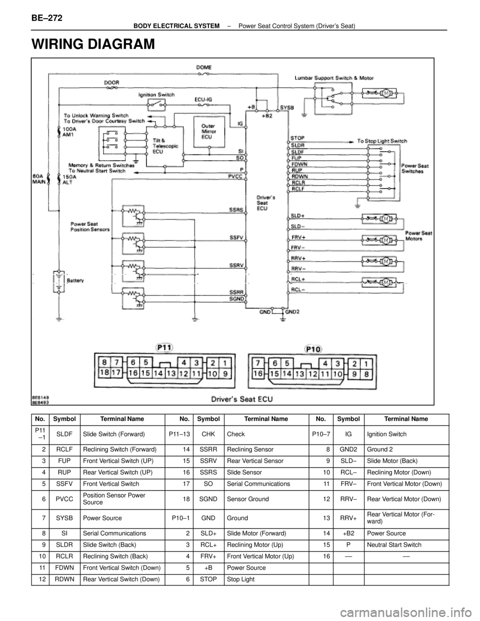
WIRING DIAGRAM
No.SymbolTerminal NameNo.SymbolTerminal NameNo.SymbolTerminal Name
P11
±1SLDFSlide Switch (Forward)P11±13CHKCheckP10±7IGIgnition Switch
2RCLFReclining Switch (Forward)14SSRRReclining Sensor8GND2Ground 2
3FUPFront Vertical Switch (UP)15SSRVRear Vertical Sensor9SLD±Slide Motor (Back)
4RUPRear Vertical Switch (UP)16SSRSSlide Sensor10RCL±Reclining Motor (Down)
5SSFVFront Vertical Switch17SOSerial Communications11FRV±Front Vertical Motor (Down)
6PVCCPosition Sensor Power
Source18SGNDSensor Ground12RRV±Rear Vertical Motor (Down)
7SYSBPower SourceP10±1GNDGround13RRV+Rear Vertical Motor (For-
ward)
8SISerial Communications2SLD+Slide Motor (Forward)14+B2Power Source
9SLDRSlide Switch (Back)3RCL+Reclining Motor (Up)15PNeutral Start Switch
10RCLRReclining Switch (Back)4FRV+Front Vertical Motor (Up)16±±±±
11FDWNFront Vertical Switch (Down)5+BPower Source
12RDWNRear Vertical Switch (Down)6STOPStop Light
BE±272±
BODY ELECTRICAL SYSTEM Power Seat Control System (Driver's Seat)
WhereEverybodyKnowsYourName
Page 668 of 4087
CIRCUIT INSPECTION
+B Power Source Circuit
CIRCUIT DESCRIPTION
This is the power source for motors such as the slide motor and reclining mo\
tor.
DIAGNOSTIC CHARTDIAGNOSTIC CHART
Check Door fuse.NG
Check for short in all harness and
components connected to the
DOOR fuse (See attached wiring
diagram).
Check voltage between terminals +B, +B2
and GND of ECU connector. OK
OKProceed to next circuit inspection
shown on matrix chart (See page
BE±276
).
Check continuity between terminal GND
of ECU connector and body ground. NG
NGRepair or replace harness or
connector.
OK
Check and repair harness or connector
between ECU and battery.
WIRING DIAGRAM
BE±284±
BODY ELECTRICAL SYSTEM Power Seat Control System (Driver's Seat)
WhereEverybodyKnowsYourName
Page 669 of 4087
OKNG
NGOK
OKNG
INSPECTION PROCEDURE
1Check DOOR fuse.
Check for short in all the harness and components con-
nected to the DOOR fuse (See attached wiring diagram).
2Check voltage between terminals +B, +B2 and GND of ECU connector.
C
OK
PRemove ECU with connectors still connected.
Measure voltage between terminals +B, +B2 and GND
of ECU connector.
Voltage: 10 ± 14 V
Proceed to next circuit inspection shown on matrix chart
(See page BE±276.)
3Check continuity between terminal GND of ECU connector and body ground.
C
OK
Measure resistance between terminal GND of ECU and
body ground.
Resistance: 1 � or less.
Repair or replace harness or connector.
Check and repair harness or connector between
ECU and battery.
±
BODY ELECTRICAL SYSTEM Power Seat Control System (Driver's Seat)BE±285
WhereEverybodyKnowsYourName
Page 670 of 4087
WIRING DIAGRAM
ECU Power Source Circuit
CIRCUIT DESCRIPTION
This circuit provides power for ECU operation and is also the power source f\
or the sensors.
DIAGNOSTIC CHARTDIAGNOSTIC CHART
Check DOME fuse.NGCheck for short in all the harness
and components connected to
DOME fuse.
(See attached wiring diagram).
OK
Check voltage between terminals SYSB
and SGND of ECU connector. Proceed to next circuit inspection
shown on matrix chart
(See page
BE±276).
Check continuity between terminal SGND
of ECU connector and body ground. OK
NG
OK NG
Replace or repair harness or
connector.
Check and repair harness or connector
between ECU and battery.
BE±286±
BODY ELECTRICAL SYSTEM Power Seat Control System (Driver's Seat)
WhereEverybodyKnowsYourName