Page 571 of 4087
Wiring and Connector Diagrams (Cont'd)
±
BODY ELECTRICAL SYSTEM Power Mirror Control SystemBE±185
WhereEverybodyKnowsYourName
Page 577 of 4087
FUEL LID OPENER SYSTEM
Parts Location
Wiring and Connector Diagrams
±
BODY ELECTRICAL SYSTEM Fuel Lid Opener SystemBE±191
WhereEverybodyKnowsYourName
Page 585 of 4087
Wiring and Connector Diagrams
±
BODY ELECTRICAL SYSTEM Audio SystemBE±199
WhereEverybodyKnowsYourName
Page 587 of 4087
Wiring and Connector Diagrams
±
BODY ELECTRICAL SYSTEM Audio SystemBE±201
WhereEverybodyKnowsYourName
Page 589 of 4087
Wiring and Connector Diagrams
±
BODY ELECTRICAL SYSTEM Audio SystemBE±203
WhereEverybodyKnowsYourName
Page 591 of 4087
Wiring and Connector Diagrams
±
BODY ELECTRICAL SYSTEM Audio SystemBE±205
WhereEverybodyKnowsYourName
Page 593 of 4087

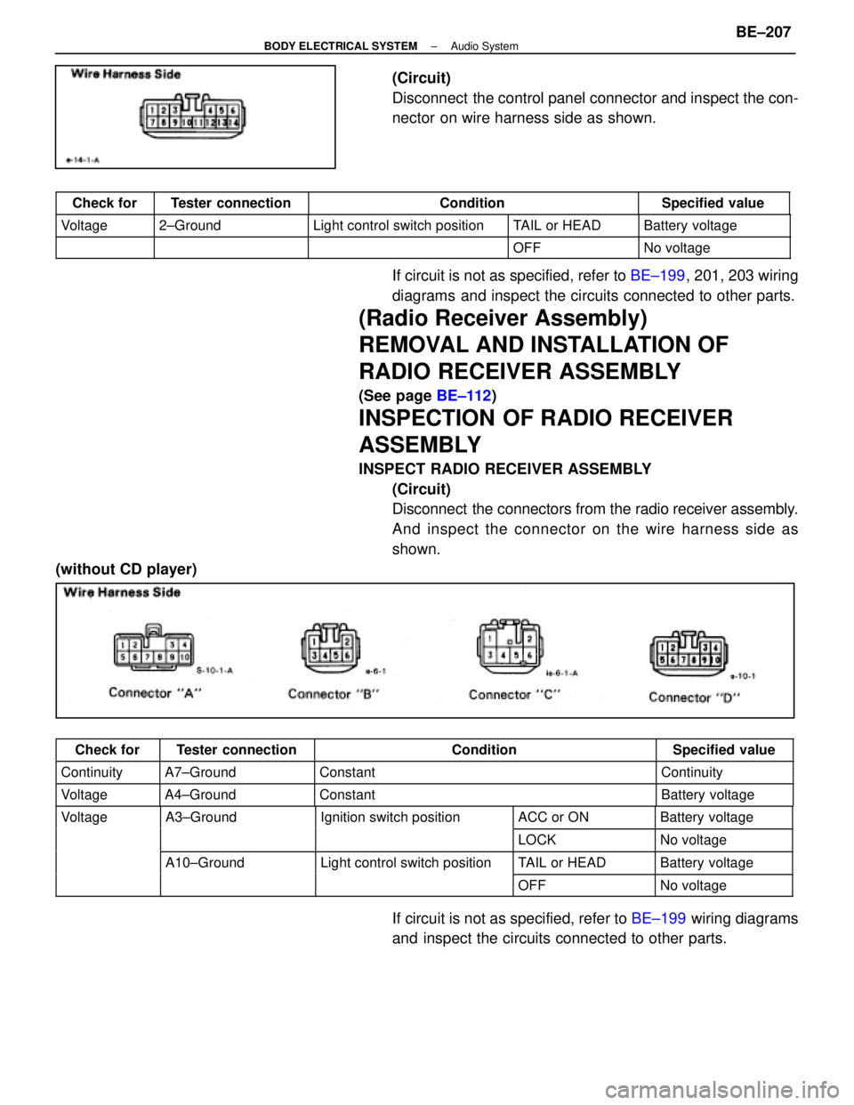
(Circuit)
Disconnect the control panel connector and inspect the con-
nector on wire harness side as shown.
Check forTester connectionConditionSpecified value
Voltage2±GroundLight control switch positionTAIL or HEADBattery voltage
OFFNo voltage
If circuit is not as specified, refer to BE±199, 201, 203 wiring
diagrams and inspect the circuits connected to other parts.
(Radio Receiver Assembly)
REMOVAL AND INSTALLATION OF
RADIO RECEIVER ASSEMBLY
(See page BE±112)
INSPECTION OF RADIO RECEIVER
ASSEMBLY
INSPECT RADIO RECEIVER ASSEMBLY
(Circuit)
Disconnect the connectors from the radio receiver assembly.
And inspect the connector on the wire harness side as
shown.
(without CD player)
Check forTester connectionConditionSpecified value
ContinuityA7±GroundConstantContinuity
VoltageA4±GroundConstantBattery voltage
VoltageA3±GroundIgnition switch positionACC or ONBattery voltageg
LOCKNo voltage
A10±GroundLight control switch positionTAIL or HEADBattery voltageg
OFFNo voltage
If circuit is not as specified, refer to BE±199 wiring diagrams
and inspect the circuits connected to other parts.
±
BODY ELECTRICAL SYSTEM Audio SystemBE±207
WhereEverybodyKnowsYourName
Page 596 of 4087

(c) Disconnect the connector and remove the wooferamplifier.
2. INSTALL WOOFER AMPLIFIER For installation, follow the removal procedure in reverse.
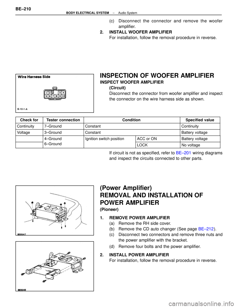
INSPECTION OF WOOFER AMPLIFIER
INSPECT WOOFER AMPLIFIER
(Circuit)
Disconnect the connector from woofer amplifier and inspect
the connector on the wire harness side as shown.
Check forTester connectionConditionSpecified value
Continuity7±GroundConstantContinuity
Voltage3±GroundConstantBattery voltage
4±GroundIgnition switch positionACC or ONBattery voltage
6±Ground
g
LOCKNo voltage
If circuit is not as specified, refer to BE±201 wiring diagrams
and inspect the circuits connected to other parts.
(Power Amplifier)
REMOVAL AND INSTALLATION OF
POWER AMPLIFIER
(Pioneer)
1. REMOVE POWER AMPLIFIER (a) Remove the RH side cover.
(b) Remove the CD auto changer (See page BE±212).
(c) Disconnect two connectors and remove three nuts and the power amplifier with the bracket.
(d) Remove four bolts and the power amplifier.
2. INSTALL POWER AMPLIFIER For installation, follow the removal procedure in reverse.
BE±210
±
BODY ELECTRICAL SYSTEM Audio System
WhereEverybodyKnowsYourName