1991 LEXUS SC300 key
[x] Cancel search: keyPage 823 of 4087

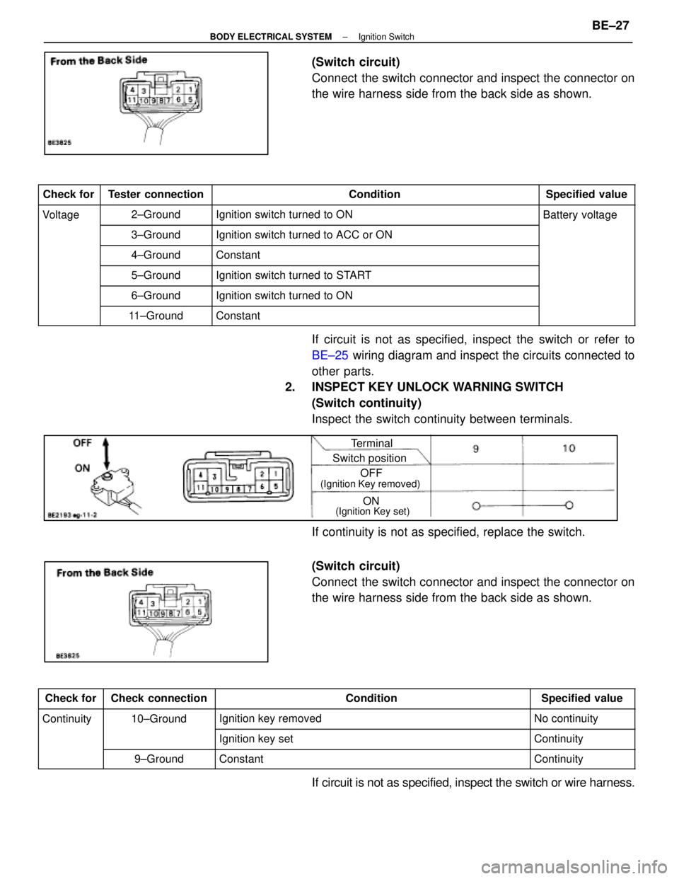
(Switch circuit)
Connect the switch connector and inspect the connector on
the wire harness side from the back side as shown.
Check forTester connectionConditionSpecified value
Voltage2±GroundIgnition switch turned to ONBattery voltage
3±GroundIgnition switch turned to ACC or ON
4±GroundConstant
5±GroundIgnition switch turned to START
6±GroundIgnition switch turned to ON
11±GroundConstant
If circuit is not as specified, inspect the switch or refer to
BE±25 wiring diagram and inspect the circuits connected to
other parts.
2. INSPECT KEY UNLOCK WARNING SWITCH
(Switch continuity)
Inspect the switch continuity between terminals.
Terminal
Switch position
ON
OFF
(Ignition Key removed)
(Ignition Key set)
If continuity is not as specified, replace the switch.
(Switch circuit)
Connect the switch connector and inspect the connector on
the wire harness side from the back side as shown.
Check forCheck connectionConditionSpecified value
Continuity10±GroundIgnition key removedNo continuity
Ignition key setContinuity
9±GroundConstantContinuity
If circuit is not as specified, inspect the switch or wire harness.
±
BODY ELECTRICAL SYSTEM Ignition SwitchBE±27
WhereEverybodyKnowsYourName
Page 845 of 4087

(Integration Relay)
REMOVAL AND INSTALLATION OF
INTEGRATION RELAY
(See page BE±16)
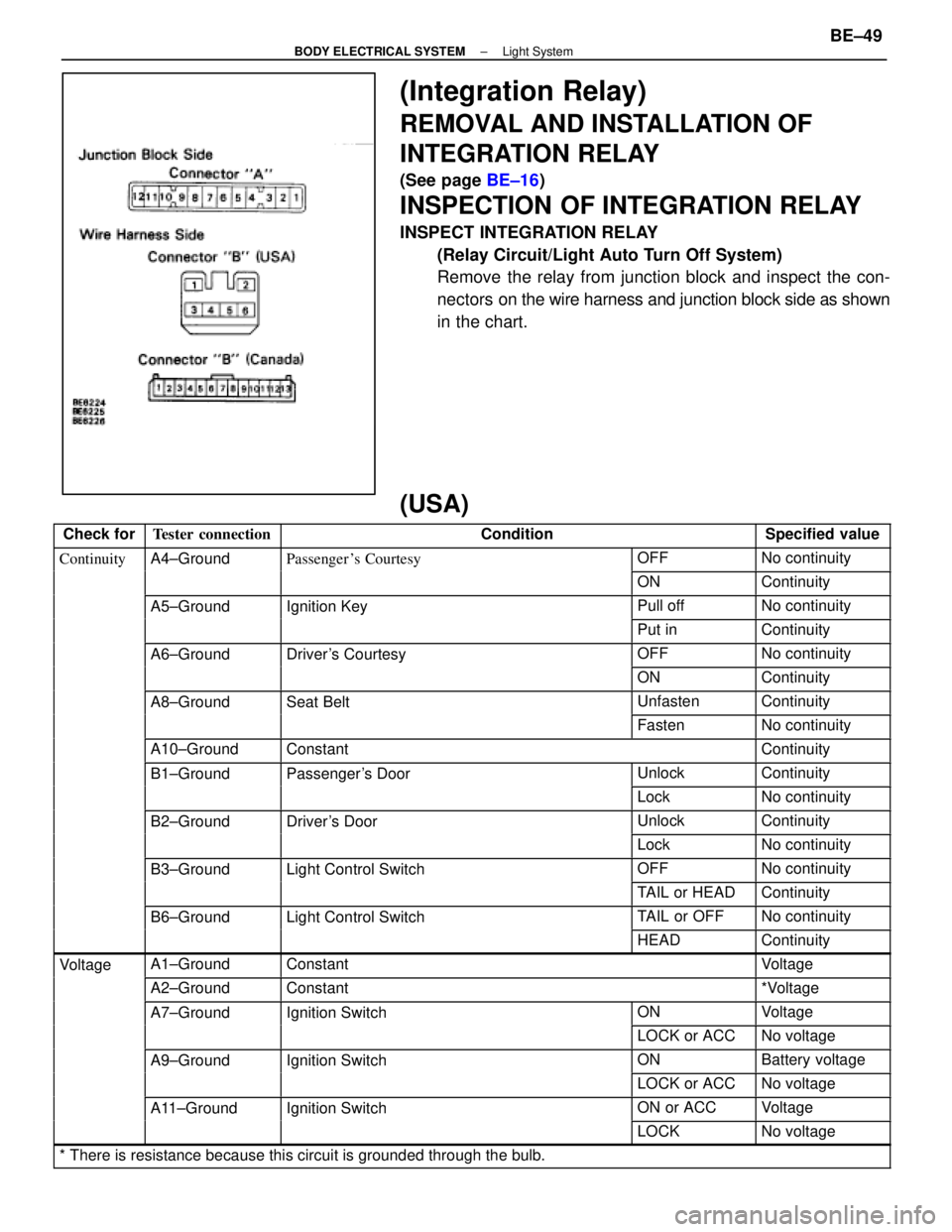
INSPECTION OF INTEGRATION RELAY
INSPECT INTEGRATION RELAY
(Relay Circuit/Light Auto Turn Off System)
Remove the relay from junction block and inspect the con-
nectors on the wire harness and junction block side as shown
in the chart.
(USA)
Check forTester connectionConditionSpecified value
ContinuityA4±GroundPassenger 's CourtesyOFFNo continuityygy
ONContinuity
A5±GroundIgnition KeyPull offNo continuitygy
Put inContinuity
A6±GroundDriver's CourtesyOFFNo continuityy
ONContinuity
A8±GroundSeat BeltUnfastenContinuity
FastenNo continuity
A10±GroundConstantContinuity
B1±GroundPassenger's DoorUnlockContinuityg
LockNo continuity
B2±GroundDriver's DoorUnlockContinuity
LockNo continuity
B3±GroundLight Control SwitchOFFNo continuityg
TAIL or HEADContinuity
B6±GroundLight Control SwitchTAIL or OFFNo continuityg
HEADContinuity
VoltageA1±GroundConstantVoltageg
A2±GroundConstant*Voltage
A7±GroundIgnition SwitchONVoltageg
LOCK or ACCNo voltage
A9±GroundIgnition SwitchONBattery voltageg
LOCK or ACCNo voltage
A11±GroundIgnition SwitchON or ACCVoltageg
LOCKNo voltage
* There is resistance because this circuit is grounded through the bulb.\
±
BODY ELECTRICAL SYSTEM Light SystemBE±49
WhereEverybodyKnowsYourName
Page 846 of 4087

(Canada)
Check forTester connectionConditionSpecified value
ContinuityA4±GroundPassenger's CourtesyOFFNo continuityygy
ONContinuity
A5±GroundIgnition KeyPull offNo continuitygy
Put inContinuity
A6±GroundDriver's CourtesyOFFNo continuityy
ONContinuity
A8±GroundSeat BeltUnfastenContinuity
FastenNo continuity
A10±GroundConstantContinuity
A12±GroundConstantContinuity
B1±GroundPassenger's DoorUnlockContinuityg
LockNo continuity
B2±GroundParking Brake
Switch PositionOFF (Switch pin
pushed in)No continuity
ON (Switch pin re-
leased)Continuity
B3±GroundDriver's DoorUnlockContinuity
LockNo continuity
B7±GroundHeadlight Dimmer
Switch PositionLow Beam or High
BeamNo continuity
FlashContinuity
B8±GroundHeadlight DimmerLow BeamNo continuityg
Switch PositionHigh Beam or FlashContinuity
B10±GroundLight Control SwitchOFFNo continuityg
HEAD or TAILContinuity
B12±GroundConstantContinuity
B13±GroundLight Control SwitchOFF or TAILNo continuityg
HEADContinuity
VoltageA1±GroundConstantVoltageg
A2±GroundConstant*Voltage
A7±GroundIgnition SwitchONVoltageg
LOCK or ACCNo voltage
A9±GroundIgnition SwitchON*Voltageg
LOCK or ACCNo voltage
A11±GroundIgnition SwitchON or ACCVoltageg
LOCKNo voltage
B4±GroundEngineSTOPNo voltageg
RunningVoltage
B11±GroundConstantVoltage
* There is resistance because this circuit is grounded through the bulb.\
If the circuit is as specified, trying replacing the relay with a
new one.
If the circuit is not as specified, refer to BE±35 wiring diagram
and inspect the circuit connected to other parts.
BE±50
±
BODY ELECTRICAL SYSTEM Light System
WhereEverybodyKnowsYourName
Page 895 of 4087

DESCRIPTION
The combination meter has various meters and gauges which show the vehicle'\
s condition, warning lights which
monitor abnormalities in the vehicle and inform the driver, indicator lights which inform the driver of the condition
of each part of vehicle, and a function for illumination and brightness ad\
justment of meters and gauges.
The component parts of this system and their functions are described in \
the following table.
Parts NameFunction
SpeedometerThe speedometer needle moves in accordance with signals from the speed s\
ensor to
indicate the vehicle's speed.
TachometerThe tachometer needle moves in accordance with signals from the igniter \
to indicate the
engine's speed.
Water Temperatrue
GaugeThe water temperature gauge's needle moves in accordance with signals from the send-
er gauge and indicates the temperature of the engine coolant.
Fuel GaugeThe fuel gauge needle moves in accordance with signals from the sender g\
auge, indicat-
ing the amount of fuel remaining in the fuel tank.
OdometerThe odometer counts the total distance traveled by the vehicle in accord\
ance with pulse
signals from the speed sensor.
Twin Trip Switch
The twin trip meter counts the distance traveled by the vehicle in accor\
dance with pulse
signals from the speed sensor. It can be reset using a switch and can be used to switch
between trip meters A and B.
Circuit Plate
This plate contains the circuitry for each meter and gauge and for each \
warning light and
indicator light, as well as an internal engine oil level warning drive c\
ircuit, drive circuits for
the odometer and trip meter and brightness adjustment circuitry for each\
indicator.
Speed SensorMounted in the transmission, this sensor outputs pulse signals to the co\
mbination meter
in accordance with the speed of the output shaft.
Twin Trip SwitchOperation of this switch switches between the A and B trip meters and se\
nds reset sig-
nals to the combination meter.
Water
Temperature Sender
GaugeThis sender converts engine coolant temperatures to a resistance value i\
n signal form to
the combination meter.
Fuel Sender GaugeThis sender converts the level of fuel remaining in fuel tank to resista\
nce value and
sends the resistance value in signal form to combination meter.
Rheostat Light
Control VolumeIn order to adjust the degree of illumination of the combination meter, the resistance val-
ue of the built±in variable resistor is sent to the combination meter\
and rheostat light
control.
Fuel Level Warning
SwitchWhen the level of fuel remaining falls below a predetermined level, cont\
inuity is estab-
lished with this switch, which is built into the fuel sender gauge, caus\
ing a warning light
to light up.
Low Oil Pressure
Warning SwitchThis switch is mounted on the engine block. Continuity is established in\
this switch when
the oil pressure is low, causing a warning light to light up.
Integration Relay (Seat
Belt Warning Relay)
This relay receives current from fuse GAUGE and DOME and is connected to\
each
buckle switch, door courtesy switch, key unlock warning switch and warni\
ng light. As
part of the seat belt warning system, it sounds a chime and lights a war\
ning light when
seat belts are unfastened. As part of the key unlock warning system, it \
sounds a chime
when the set conditions are fulfilled.
Light Failure SensorThis sensor senses when a bulb in rear combination light is burnt out an\
d lights up a
warning light.
BE±96±
BODY ELECTRICAL SYSTEM Combination Meter
WhereEverybodyKnowsYourName
Page 1435 of 4087

(c) Measure the protrusion of the push rod from the housing end.
Protrusion:
10.5 ± 11.5 mm (0.413 ± 0.453 in.)
If the protrusion is not as specified, replace the tensioner.
EG21R±02
TIMING BELT INSTALLATION
See Components for Removal and Installation:
1. INSTALL CRANKSHAFT TIMING PULLEY
(a) Align the timing pulley set key with the key groove of thepulley.
(b) Using SST and a hammer, tap in the timing pulley, facing the flange side inward.
SST 09223±46011
2. INSTALL NO.1 IDLER PULLEY
(a) Apply adhesive 2 or 3 threads of the pivot bolt.
Adhesive: Part No. 08833±00080, THREE BOND 1344,
LOCTITE 242 or equivalent
(b) Using a 10 mm hexagon wrench, install the plate washer and
idler pulley with the pivot bolt.
Torque: 34 N Vm (350 kgf Vcm, 25 ft Vlbf)
(c) Check that the pulley bracket moves smoothly.
3. INSTALL NO.2 IDLER PULLEY
(a) Install the idler pulley with the bolt.
Torque: 34 N Vm (350 kgf Vcm, 25 ft Vlbf)
(b) Check that the idler pulley moves smoothly.
4. TEMPORARILY INSTALL TIMING BELT
NOTICE: The engine should be cold.
(a) Using the crankshaft pulley bolt, turn the crankshaft and align
the timing marks of the crankshaft timing pulley and oil pump
body.
±
1UZ±FE ENGINE ENGINE MECHANICALEG±59
WhereEverybodyKnowsYourName
Page 1437 of 4087

8. INSTALL HYDRAULIC PUMP
(a) Install the hydraulic pump, solenoid valve connector clampand crankshaft position sensor wire clamp with the 2 bolts
and 2 nuts.
Torque:
16 NVm (160 kgf Vcm, 12 ft Vlbf) for 12 mm head
30 N Vm (310 kgf Vcm, 22 ft Vlbf) for 14 mm head
HINT: Each bolt length is indicated in the illustration.
Bolt length:
106 mm (4.17 in.) for A of 12 mm head
114 mm (4.49 in.) for B of 14 mm head
(b) Connect the solenoid valve connector.
9. INSTALL CRANKSHAFT PULLEY
(a) Align the pulley set key with the key groove of the crankshaft pulley.
(b) Using SST and a hammer, tap in the crankshaft pulley. SST 09223±46011
(c) Using SST, install the pulley bolt. SST 09213±70010, 09330±00021
Torque: 245 N Vm (2,500 kgf Vcm, 181 ft Vlbf)
10. INSTALL RH CAMSHAFT TIMING PULLEY
(a) Align the camshaft knock pin with the knock pin groove of the
timing pulley, and slide on the timing pulley.
(b) Slide the timing pulley on the camshaft, facing the ªRº mark forward.
(c) Using SST, install the pulley bolt. SST 09278±54012
Torque: 108 N Vm (1,100 kgf Vcm, 80 ft Vlbf)
±
1UZ±FE ENGINE ENGINE MECHANICALEG±61
WhereEverybodyKnowsYourName
Page 1696 of 4087

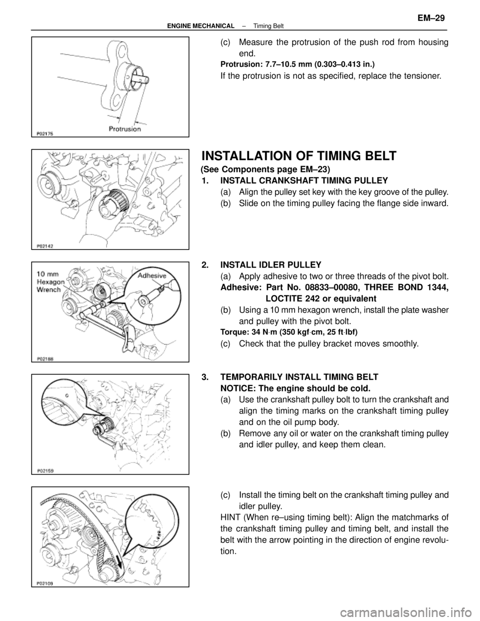
(c) Measure the protrusion of the push rod from housingend.
Protrusion: 7.7±10.5 mm (0.303±0.413 in.)
If the protrusion is not as specified, replace the tensioner.
INSTALLATION OF TIMING BELT
(See Components page EM±23)1. INSTALL CRANKSHAFT TIMING PULLEY (a) Align the pulley set key with the key groove of the pulley.
(b) Slide on the timing pulley facing the flange side inward.
2. INSTALL IDLER PULLEY (a) Apply adhesive to two or three threads of the pivot bolt.
Adhesive: Part No. 08833±00080, THREE BOND 1344, LOCTITE 242 or equivalent
(b) Using a 10 mm hexagon wrench, install the plate washer
and pulley with the pivot bolt.
Torque: 34 N Vm (350 kgf Vcm, 25 ft Vlbf)
(c) Check that the pulley bracket moves smoothly.
3. TEMPORARILY INSTALL TIMING BELT NOTICE: The engine should be cold.
(a) Use the crankshaft pulley bolt to turn the crankshaft andalign the timing marks on the crankshaft timing pulley
and on the oil pump body.
(b) Remove any oil or water on the crankshaft timing pulley and idler pulley, and keep them clean.
(c) Install the timing belt on the crankshaft timing pulley and
idler pulley.
HINT (When re±using timing belt): Align the matchmarks of
the crankshaft timing pulley and timing belt, and install the
belt with the arrow pointing in the direction of engine revolu-
tion.
±
ENGINE MECHANICAL Timing BeltEM±29
WhereEverybodyKnowsYourName
Page 1697 of 4087

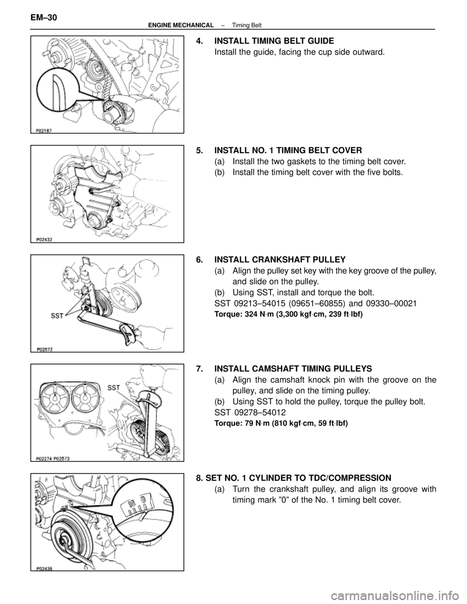
4. INSTALL TIMING BELT GUIDEInstall the guide, facing the cup side outward.
5. INSTALL NO. 1 TIMING BELT COVER (a) Install the two gaskets to the timing belt cover.
(b) Install the timing belt cover with the five bolts.
6. INSTALL CRANKSHAFT PULLEY (a) Align the pulley set key with the key groove of the pulley,
and slide on the pulley.
(b) Using SST, install and torque the bolt.
SST 09213±54015 (09651±60855) and 09330±00021
Torque: 324 N Vm (3,300 kgf Vcm, 239 ft Vlbf)
7. INSTALL CAMSHAFT TIMING PULLEYS
(a) Align the camshaft knock pin with the groove on thepulley, and slide on the timing pulley.
(b) Using SST to hold the pulley, torque the pulley bolt.
SST 09278±54012
Torque: 79 N Vm (810 kgf Vcm, 59 ft Vlbf)
8. SET NO. 1 CYLINDER TO TDC/COMPRESSION
(a) Turn the crankshaft pulley, and align its groove withtiming mark º0º of the No. 1 timing belt cover.
EM±30
±
ENGINE MECHANICAL Timing Belt
WhereEverybodyKnowsYourName