Page 788 of 4087

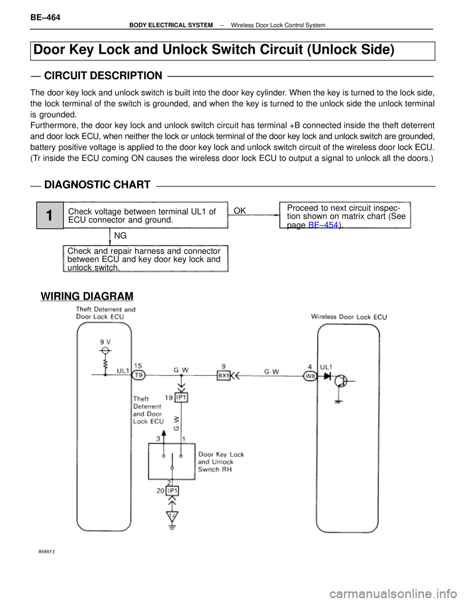
WIRING DIAGRAM
Door Key Lock and Unlock Switch Circuit (Unlock Side)
CIRCUIT DESCRIPTION
The door key lock and unlock switch is built into the door key cylinder. When the key is turned to the lock side,
the lock terminal of the switch is grounded, and when the key is turned to the unlock side the unlock terminal
is grounded.
Furthermore, the door key lock and unlock switch circuit has terminal +B\
connected inside the theft deterrent
and door lock ECU, when neither the lock or unlock terminal of the door key\
lock and unlock switch are grounded,
battery positive voltage is applied to the door key lock and unlock switch circuit of the wireless d\
oor lock ECU.
(Tr inside the ECU coming ON causes the wireless door lock ECU to output a \
signal to unlock all the doors.)
DIAGNOSTIC CHARTDIAGNOSTIC CHART
NGOK
Proceed to next circuit inspec-
tion shown on matrix chart (See
page
BE±454 ).
Check voltage between terminal UL1 of
ECU connector and ground.
Check and repair harness and connector
between ECU and key door key lock and
unlock switch.
1
BE±464±
BODY ELECTRICAL SYSTEM Wireless Door Lock Control System
WhereEverybodyKnowsYourName
Page 789 of 4087
NGOK
INSPECTION PROCEDURE
1Check voltage between terminal UL1 of ECU connector and body ground.
C
OK
P1. Remove the rear seat and RH quarter trim panel.
2. Remove the ECU.
3. Turn ignition switch on.
Measure voltage between terminal UL1 of ECU connec-
tor and body ground.
Voltage: 8 ± 10 V
Proceed to next circuit inspection shown on matrix chart
(See page BE±454).
Check and repair harness and connector between ECU and door key lock and\
unlock switch.
±
BODY ELECTRICAL SYSTEM Wireless Door Lock Control SystemBE±465
WhereEverybodyKnowsYourName
Page 790 of 4087
WIRING DIAGRAM
Door Key Lock and Unlock Switch Circuit (Lock Side)
CIRCUIT DESCRIPTION
Refer to page BE±464.
Tr inside the ECU coming ON causes the wireless door lock ECU to output a\
signal to lock all the doors.
DIAGNOSTIC CHARTDIAGNOSTIC CHART
NG OK
Proceed to next circuit inspec-
tion shown on matrix chart (See
page
BE±454 ).
Check voltage between terminal L1 of
ECU connector and body ground.
Check and repair harness and connector
between ECU and door key lock and un-
lock switch.
1
BE±466±
BODY ELECTRICAL SYSTEM Wireless Door Lock Control System
WhereEverybodyKnowsYourName
Page 791 of 4087
NGOK
INSPECTION PROCEDURE
1Check voltage between terminal L1 of wireless door lock ECU connector and bod\
y ground.
C
OK
P1. Remove the rear seat and RH quarter trim panel.
2. Remove the ECU.
3. Turn ignition switch on.
Measure voltage between terminal L1 of ECU connec-
tor and body ground.
Voltage: 8 ± 10 V
Proceed to next circuit inspection shown on matrix chart
(See page BE±454).
Check and repair harness and connector between ECU and door key lock and\
unlock switch.
±
BODY ELECTRICAL SYSTEM Wireless Door Lock Control SystemBE±467
WhereEverybodyKnowsYourName
Page 792 of 4087
WIRING DIAGRAM
Key Unlock Warning Switch Circuit
CIRCUIT DESCRIPTION
When the key is inserted in the ignition key cylinder the key unlock warning\
switch comes ON, and when the
key is not inserted switch is OFF.
When the key unlock warning switch is ON, the ECU operates the key confi\
nement prevention function.
DIAGNOSTIC CHARTDIAGNOSTIC CHART
NGOK
Proceed to next circuit inspec-
tion shown on matrix chart (See
page
BE±454 ).
Check voltage between terminal KSW of
ECU connector and body ground.
Check and repair harness and connector
between ECU and key unlock warning
switch.
1
BE±468±
BODY ELECTRICAL SYSTEM Wireless Door Lock Control System
WhereEverybodyKnowsYourName
Page 793 of 4087
NGOK
INSPECTION PROCEDURE
1Check voltage between terminal KSW of ECU connector and body ground.
C
OK
P1. Remove the rear seat and RH quarter trim panel.
2. Remove the ECU.
3. Key plate is not inserted in the key cylinder.
Measure voltage between terminal KSW of ECU con-
nector and body ground, when key plate is not inserted
in the key cylinder.
Voltage: 10 ± 14 V
Proceed to next circuit inspection shown on matrix chart
(See page BE±454).
Check and repair harness and connector between ECU and key unlock warnin\
g switch.
±
BODY ELECTRICAL SYSTEM Wireless Door Lock Control SystemBE±469
WhereEverybodyKnowsYourName
Page 821 of 4087
IGNITION SWITCH
Description
The ignition switch is supplied with power from the battery via a fusible l\
ink. Power is supplied to each fuse
and relay according to the position of the switch, whether ªCCº ``ONº or ªSTARTº. The key unlock warning
switch, which detects the set condition of the key, is built into this switch.
Parts Location
Wiring and Connector Diagrams
±
BODY ELECTRICAL SYSTEM Ignition SwitchBE±25
WhereEverybodyKnowsYourName
Page 822 of 4087

Parts Inspection
(Ignition Switch and Key Unlock
Warning Switch)
REMOVAL AND INSTALLATION OF
IGNITION SWITCH AND KEY UNLOCK
WARNING SWITCH
1. DISCONNECT BATTERY TERMINALSCAUTION: Work must be started after approx. 20 se-
conds or longer from the time the ignition switch is
turned to the ºLOCKº position and negative (±) terminal
cable is disconnected from the battery.
2. REMOVE FOLLOWING PARTS: (See page BO±112)
w No. 1 under cover
w No. 1 lower finish panel
w Console box assembly
w Instrument panel lower center
3. REMOVE IGNITION SWITCH (a) Disconnect connector.
(b) Remove three screws and the switch from the keycylinder and wire harness clamp.
4. INSTALL IGNITION SWITCH For installation, follow the removal procedure in reverse.
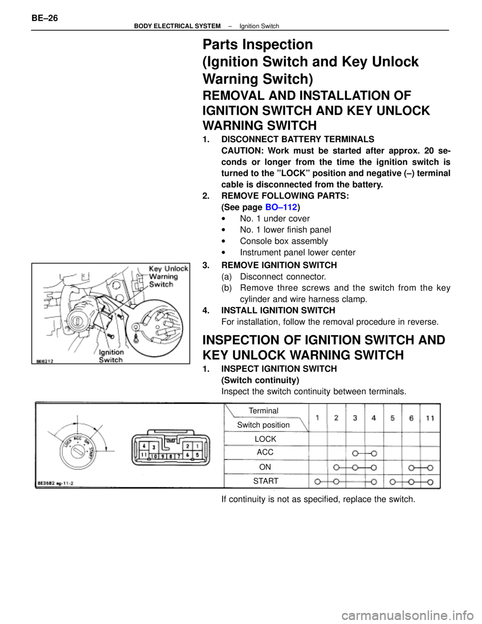
INSPECTION OF IGNITION SWITCH AND
KEY UNLOCK WARNING SWITCH
1. INSPECT IGNITION SWITCH(Switch continuity)
Inspect the switch continuity between terminals.
Terminal
Switch position LOCKACC
ON
START
If continuity is not as specified, replace the switch.
BE±26
±
BODY ELECTRICAL SYSTEM Ignition Switch
WhereEverybodyKnowsYourName