Page 3335 of 4087
wPack with grease all over the ball contact surface inside
the joint.
6. ASSEMBLE BOOT TO INBOARD JOINT
Before assembling the boot, pack with grease.
Grease capacity:
100±105 g (0.22±0.23 lb, 3.5±3.7 oz.)
HINT: Use the grease supplied in the boot kit.
NOTICE:
wKeep grease off the joint connection groove of the boot.
w Pack with grease all over the ball contact surface inside
the joint.
7. INSTALL NEW BOOT CLAMPS TO BOTH BOOTS
(a) Position the clamp onto the boot. HINT: Pinch the inboard side of the boot clamp, as shown in
the illustration.
(b) Place SST onto the clamp. SST 09521±24010
(c) Tighten SST so that the clamp is pinched.
NOTICE: Do not overtighten the SST.
(d) Using SST, adjust the clearance of the clamp. SST 09240±00020
Clearance:
0.8 mm (0.031 in.) or less
SA±72±
SUSPENSION AND AXLE REAR DRIVE SHAFT
WhereEverybodyKnowsYourName
Page 3336 of 4087
 The drive shaft is designed to move + 20 mm from the normalposition.
Drive shaft standard length:
RH 598.5 mm (23.563 in.)
LH 553.5 mm (21.791 in.)
8. INSTALL NEW END COVER
(a) Pack grease int")
(e) The drive shaft is designed to move + 20 mm from the normalposition.
Drive shaft standard length:
RH 598.5 mm (23.563 in.)
LH 553.5 mm (21.791 in.)
8. INSTALL NEW END COVER
(a) Pack grease into the end cover.
Grease capacity:50±55 g (0.11±0.12 lb, 1.8±1.9 oz.)
(b) Remove grease from the surface of the inboard joint facingthe cover.
(c) Glue on a new gasket, with the side with adhesive on it facing
toward the outer race side of the inboard joint.
(d) Align the bolt holes of the cover with those of the inboard joint.
(e) Install the 6 hexagon bolts and washer from the end cover side.
(f) Install the 6 nuts to the boot side.
(g) Using a 10 mm hexagon wrench, tighten the bolts. Do this in
the order shown, and repeat several times.
(h) Check that the claw of the end cover touches the inboard joint.
9. CHECK DRIVE SHAFT Check that operation of the joint is smooth within the sliding
region in the axial direction.
HINT: If a large angle is used for the cross±groove type joint,
the joint will feel like it is catching, but this does not indicate
an abnormality.
±
SUSPENSION AND AXLE REAR DRIVE SHAFTSA±73
WhereEverybodyKnowsYourName
Page 3337 of 4087
REAR DIFFERENTIAL
DESCRIPTION
SA091±07
The differential has an 8 inch ring gear to ensure accurate operation at high p\
ower output and high speed.
The differential is carried by a rear suspension member via rubber mounts to su\
ppress vibration and noise
being transmitted to the body.
SA±74±
SUSPENSION AND AXLE REAR DIFFERENTIAL
WhereEverybodyKnowsYourName
Page 3338 of 4087
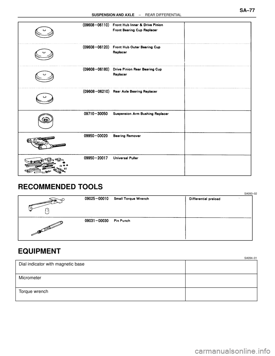
PREPARATION
SST (SPECIAL SERVICE TOOLS)
SA092±02
±
SUSPENSION AND AXLE REAR DIFFERENTIALSA±75
WhereEverybodyKnowsYourName
Page 3339 of 4087
SA±76±
SUSPENSION AND AXLE REAR DIFFERENTIAL
WhereEverybodyKnowsYourName
Page 3340 of 4087
RECOMMENDED TOOLS
SA093±02
EQUIPMENT
SA094±01������������������\
������� �
������������������\
������
������������������\
�������Dial indicator with magnetic base������������ �
�����������
������������
������������������\
������� �
������������������\
������
������������������\
�������Micrometer
������������������\
������� �
������������������\
������
������������������\
�������Torque wrench
±
SUSPENSION AND AXLE REAR DIFFERENTIALSA±77
WhereEverybodyKnowsYourName
Page 3341 of 4087

SA095±04������������������\
������� �
������������������\
������
�
������������������\
������
�
������������������\
������
������������������\
�������
08826±00110")
SSM (SPECIAL SERVICE MATERIALS)
SA095±04������������������\
������� �
������������������\
������
�
������������������\
������
�
������������������\
������
������������������\
�������
08826±00110 Seal packing 1389,
THREE BOND 1389 or equivalent������������ �
�����������
�
�����������
�
�����������
������������
Differential Carrier x Cover
������������������\
������� �
������������������\
������
�
������������������\
������
������������������\
�������
08833±00100 THREE BOND 1360K or equivalentDifferential Case x Ring Gear
LUBRICANT
SA096±02
������������ ������������Item������������� �������������Capacity������������� �������������Classification
������������ �
�����������
�
�����������
�
�����������
�
�����������
������������
Differential oil
������������� �
������������
�
������������
�
������������
�
������������
�������������
1.35 liters (1.43 US qts, 1.19 lmp. qts)
������������� �
������������
�
������������
�
������������
�
������������
�������������
API GL±5 Hypoid Gear Oil
[Above±18
�C (0 �F)]
SAE 90
[Below±18 �C (0 �F)]
SAE 80W or 80W±90
SA±78±
SUSPENSION AND AXLE REAR DIFFERENTIAL
WhereEverybodyKnowsYourName
Page 3342 of 4087
ON±VEHICLE REPAIR
COMPONENTS
SA097±02
SIDE GEAR SHAFT OIL SEAL
REPLACEMENT
SA0V1±04
1. DRAIN DIFFERENTIAL OIL
2. REMOVE REAR DRIVE SHAFT(See page SA±65)
3. REMOVE SIDE GEAR SHAFT
(a) Using SST and 2 bolts, remove the side gear shaft. SST 09520±22010
(b) Remove the snap ring from the side gear shaft.
4. REMOVE SIDE GEAR SHAFT OIL SEAL Using SST, remove the oil seal.
SST 09308±00010
±
SUSPENSION AND AXLE REAR DIFFERENTIALSA±79
WhereEverybodyKnowsYourName


SA092±02
±
SUSPENSION AND AXLE REAR DIFFERENTIALSA±75
WhereEverybodyKnowsYourName")


3. REMOVE SIDE GEAR SHAFT
(a) Using S")