Page 116 of 4087
 Remove console upper panel.(See page BO-111 ).
(2) Remove A/C control assembly with connec±")
Check voltage between terminals HR of air conditioner control assem-
bly connector and body ground.
(1) Remove console upper panel.(See page BO-111 ).
(2) Remove A/C control assembly with connec±
tors still connected.
Proceed to next circuit inspection shown on ma-
trix chart (See page AC-36).
Check heater main relay.
Check continuity between each pair of terminals of
heater main relay shown below.
Measure voltage between terminals HR of air condi-
tioner control assembly and body ground when
ignition switch is on and off.
(1) Apply battery voltage between terminals 1
and 3
(2) Check continuity between each pair of ter±minal shown below.
Replace heater main relay.
Remove HTR fuse from J/B No. 1.
Check continuity of HTR fuse
Continuity
Check for short in all the harness and
components connected to the HTR fuse
See attached wiring diagram).
Check and repair harness and connector between air conditioner control \
assembly and battery.
INSPECTION PROCEDURE
±
AIR CONDITIONING SYSTEM TroubleshootingAC±77
WhereEverybodyKnowsYourName
Page 117 of 4087
������������������\
������������������\
�
������������������\
�����������������
������������������\
������������������\
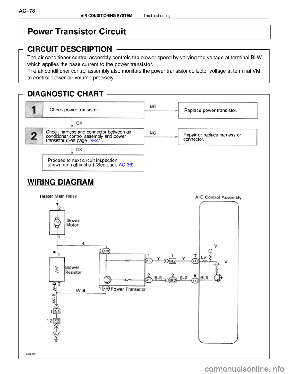
Power Transistor Circuit
CIRCUIT DESCRIPTION
The air conditioner control assembly controls the blower speed by varying the vo\
ltage at terminal BLW
which applies the base current to the power transistor.
The air conditioner control assembly also monitors the power transistor col\
lector voltage at terminal VM,
to control blower air volume precisely.
DIAGNOSTIC CHART
WIRING DIAGRAM
Check power transistor.
Check harness and connector between air
conditioner control assembly and power
transistor (See page
IN±27).
Proceed to next circuit inspection
shown on matrix chart (See page AC-36).
Replace power transistor.
Repair or replace harness or
connector.
AC±78±
AIR CONDITIONING SYSTEM Troubleshooting
WhereEverybodyKnowsYourName
Page 119 of 4087
������������������\
������������������\
�
������������������\
�����������������
������������������\
������������������\
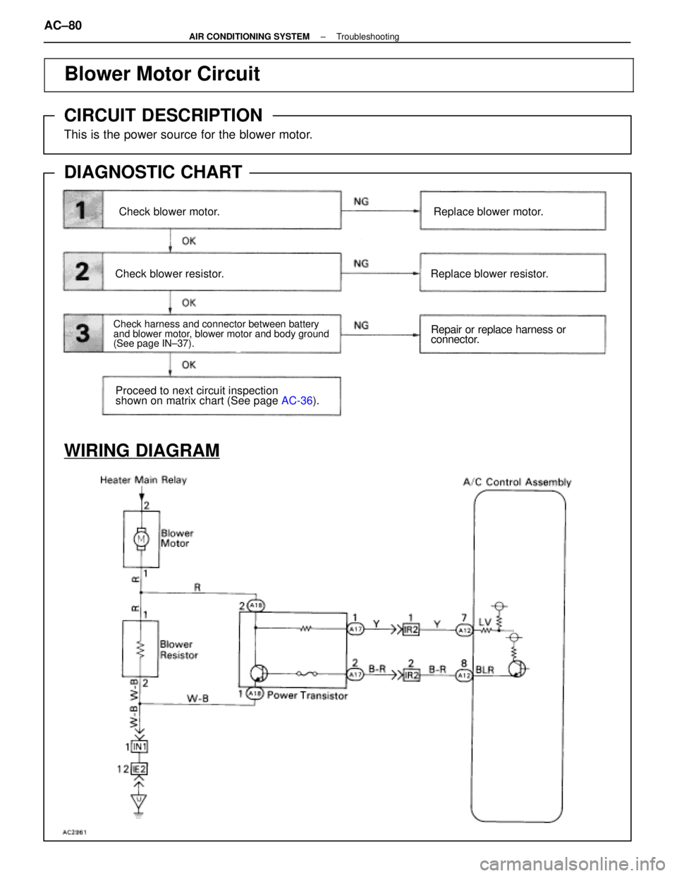
Blower Motor Circuit
CIRCUIT DESCRIPTION
This is the power source for the blower motor.
DIAGNOSTIC CHART
WIRING DIAGRAM
Check blower motor.
Check harness and connector between battery
and blower motor, blower motor and body ground
(See page IN±37).
Check blower resistor.
Replace blower motor.Replace blower motor.
Replace blower resistor.
Repair or replace harness or
connector.
Proceed to next circuit inspection
shown on matrix chart (See page
AC-36).
AC±80±
AIR CONDITIONING SYSTEM Troubleshooting
WhereEverybodyKnowsYourName
Page 121 of 4087
������������������\
������������������\
�
������������������\
�����������������
������������������\
������������������\
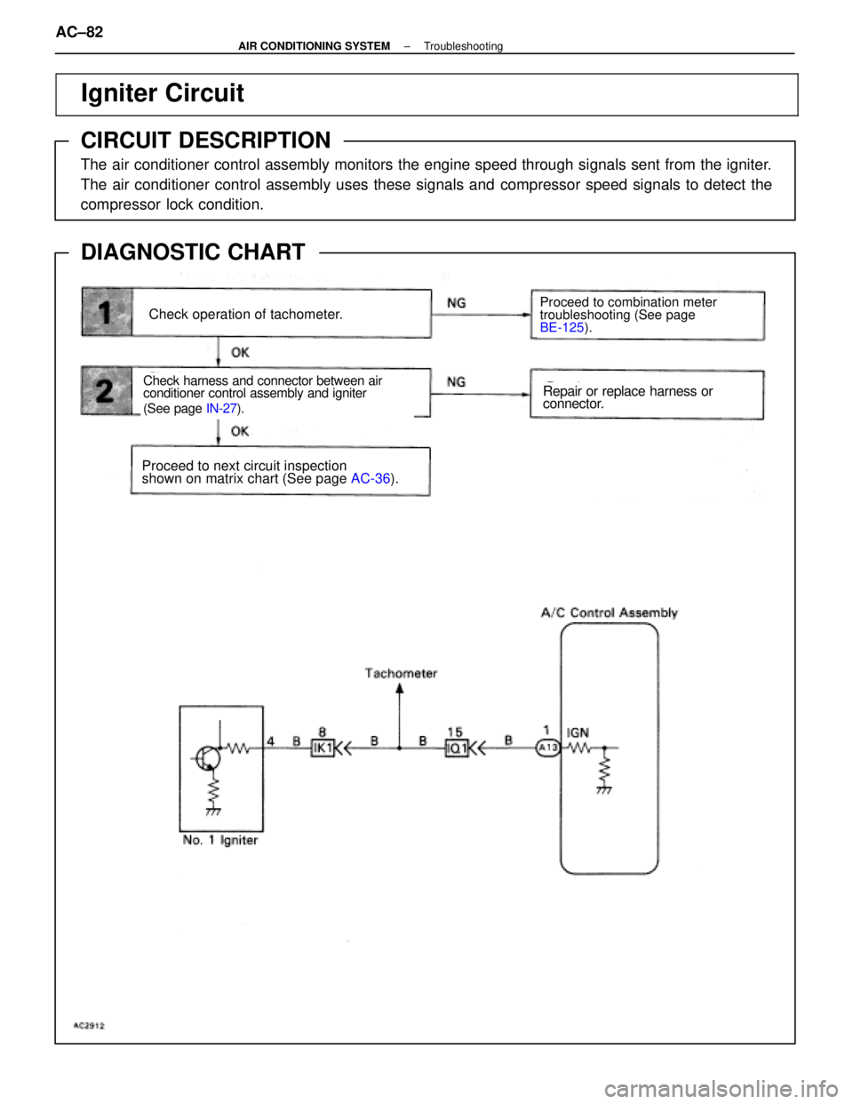
Igniter Circuit
CIRCUIT DESCRIPTION
The air conditioner control assembly monitors the engine speed through sign\
als sent from the igniter.
The air conditioner control assembly uses these signals and compressor speed signals to detect the
compressor lock condition.
DIAGNOSTIC CHART
WIRING DIAGRAM
Check operation of tachometer.
Check harness and connector between air
conditioner control assembly and igniter
(See page IN-27).
Proceed to combination meter
troubleshooting (See page
BE-125 ).
Proceed to next circuit inspection
shown on matrix chart (See page AC-36).
Repair or replace harness or
connector.
AC±82±
AIR CONDITIONING SYSTEM Troubleshooting
WhereEverybodyKnowsYourName
Page 123 of 4087
������������������\
������������������\
�
������������������\
�����������������
������������������\
������������������\
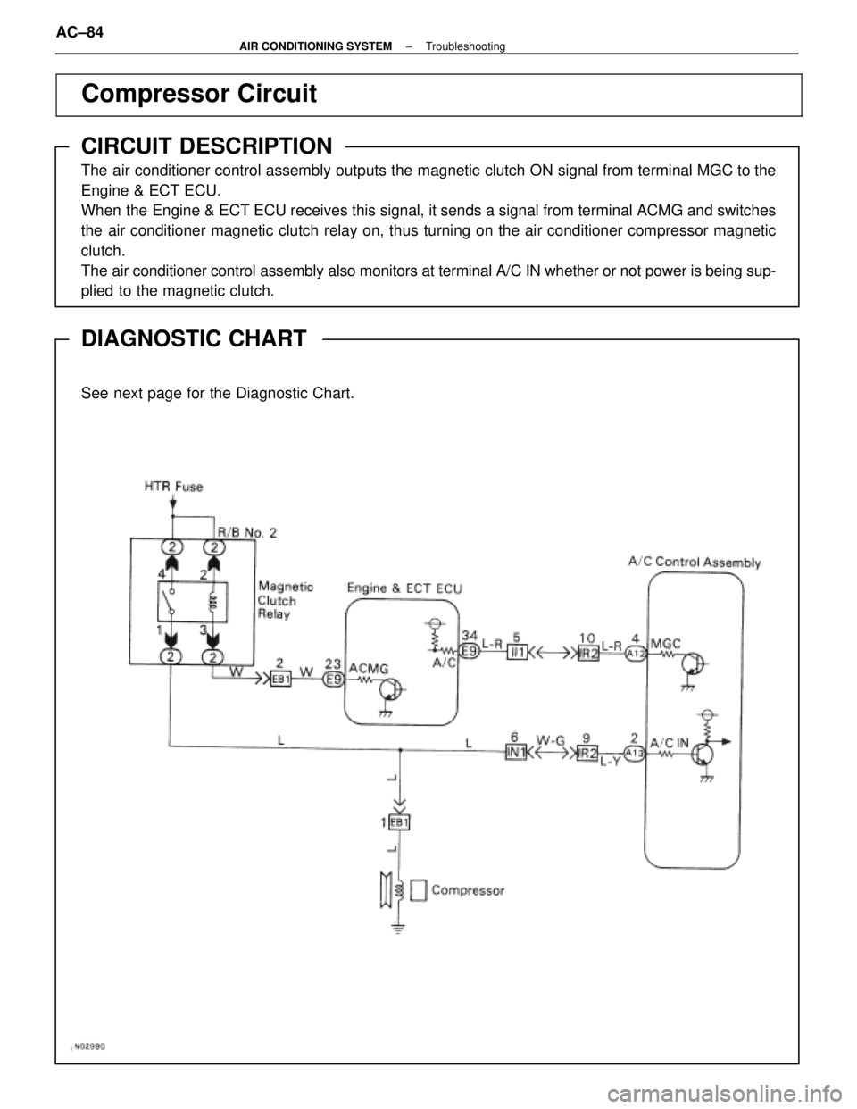
Compressor Circuit
CIRCUIT DESCRIPTION
The air conditioner control assembly outputs the magnetic clutch ON signal \
from terminal MGC to the
Engine & ECT ECU.
When the Engine & ECT ECU receives this signal, it sends a signal from terminal A\
CMG and switches
the air conditioner magnetic clutch relay on, thus turning on the air condi\
tioner compressor magnetic
clutch.
The air conditioner control assembly also monitors at terminal A/C IN wheth\
er or not power is being sup-
plied to the magnetic clutch.
DIAGNOSTIC CHART
See next page for the Diagnostic Chart.
WIRING DIAGRAM
AC±84±
AIR CONDITIONING SYSTEM Troubleshooting
WhereEverybodyKnowsYourName
Page 128 of 4087

������������������\
������������������\
�
������������������\
�����������������
������������������\
������������������\
Water Valve VSV Circuit
CIRCUIT DESCRIPTION
If the target air mix damper position is on the hot side beyond a predeter\
mined level, the A/C control
assembly turns ON Tr inside the A/C control assembly.
This turns the water valve VSV ON so that engine coolant flows to the he\
ater core.
If the target air mix damper position is on the cool side beyond a prede\
termined level, the A/C control
assembly OFF Tr inside the A/C control assembly.
This turns OFF the VSV and stops circulation of engine coolant to the he\
ater core, thus increasing the
cooling performance.
DIAGNOSTIC CHART
Check voltage between terminal WV of A/C
control assembly connector and body
ground .
Check water valve VSV.
Check for open and short in harness
and connector between VSV and A/C
control assembly .
Check and replace A/C control assembly.
Replace water valve VSV.
Repair or replace harness or
connector.
Proceed to next circuit inspection
shown on matrix chart
(See page
AC-36).
WIRING DIAGRAM
AC±90±
AIR CONDITIONING SYSTEM Troubleshooting
WhereEverybodyKnowsYourName
Page 130 of 4087

������������������\
������������������\
�
������������������\
�����������������
������������������\
������������������\
Temperature Control Switch Circuit
CIRCUIT DESCRIPTION
By turning the temp. control switch, the set temperature of the
A/C can be adjusted in steps of 1
°F (USA) or 0.5 °C (Canada).
Turning the switch fully will set the A/C to MAX. COLD or MAX.
HOT.
The ECU calculates the set temperature from the combination
of Hi (5 V) or Low (0 V) terminals SET 1 ~ 5 of the temp. control
SW and displays the set temperature on the LCD display.
If a malfunction occurs in the temp. control SW circuit, malfunc-
tions such as not being able to set the desired temperature oc-
cur.
DIAGNOSTIC CHART
WIRING DIAGRAM
Check for open and short in harness and
connector between A/C control assembly and
temp. control SW.
Check temp. control switch.
Proceed to next circuit inspection
shown on matrix chart (See page
AC-36 ).
Replace temp. control switch.
Repair or replace harness or
connector.
Check and replace A/C control assembly.
Check voltage between terminal SET 1 ~ 5
and SG of A/C control assembly.
AC±92±
AIR CONDITIONING SYSTEM Troubleshooting
WhereEverybodyKnowsYourName
Page 135 of 4087
������������������\
������������������\
�
������������������\
�����������������
������������������\
������������������\
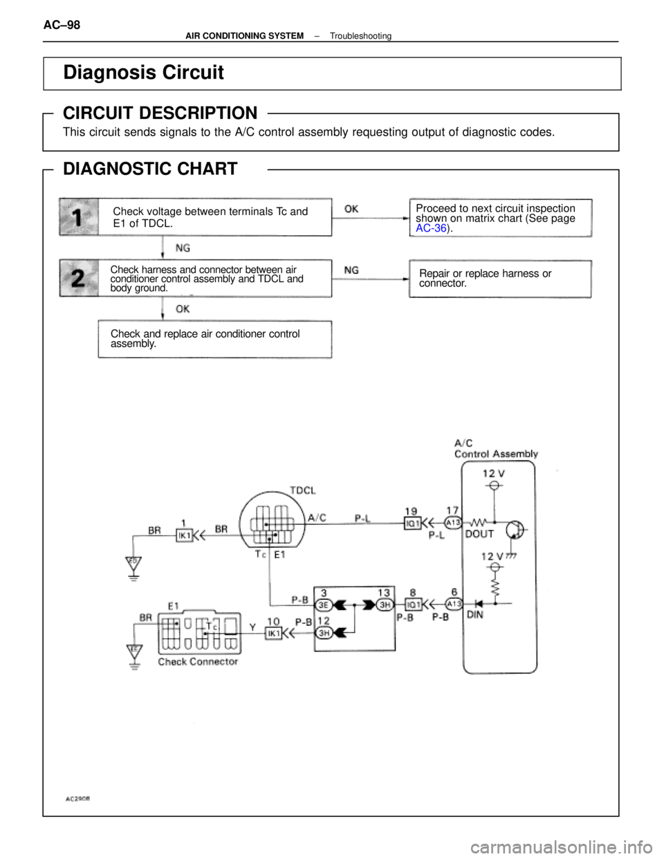
Diagnosis Circuit
CIRCUIT DESCRIPTION
This circuit sends signals to the A/C control assembly requesting output of \
diagnostic codes.
DIAGNOSTIC CHART
WIRING DIAGRAM
Check voltage between terminals Tc and
E1 of TDCL.
Check harness and connector between air
conditioner control assembly and TDCL and
body ground.
Proceed to next circuit inspection
shown on matrix chart (See page
AC-36
).
Repair or replace harness or
connector.
Check and replace air conditioner control
assembly.
AC±98±
AIR CONDITIONING SYSTEM Troubleshooting
WhereEverybodyKnowsYourName