Page 2553 of 4087
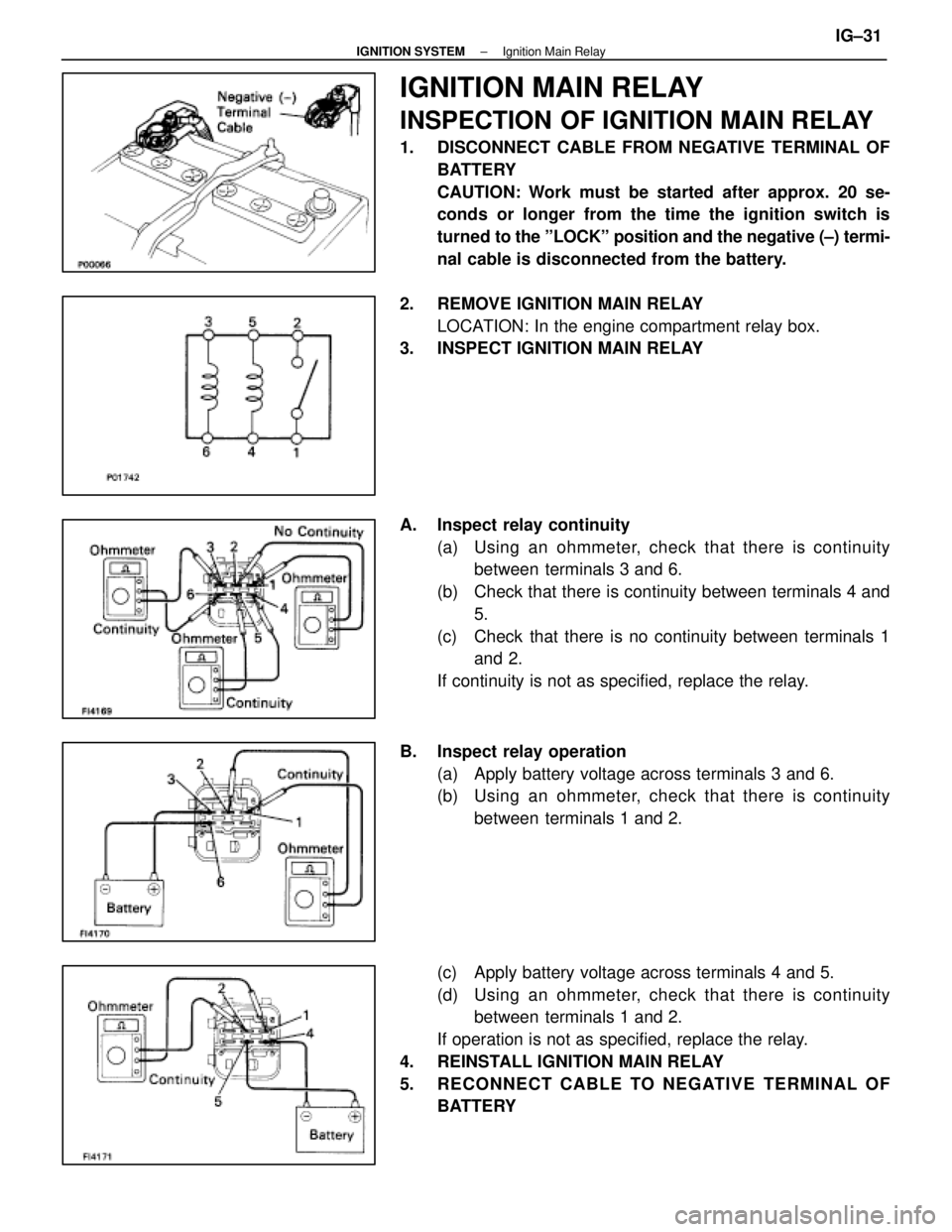
IGNITION MAIN RELAY
INSPECTION OF IGNITION MAIN RELAY
1. DISCONNECT CABLE FROM NEGATIVE TERMINAL OFBATTERY
CAUTION: Work must be started after approx. 20 se-
conds or longer from the time the ignition switch is
turned to the ºLOCKº position and the negative (±) termi-
nal cable is disconnected from the battery.
2. REMOVE IGNITION MAIN RELAY LOCATION: In the engine compartment relay box.
3. INSPECT IGNITION MAIN RELAY
A. Inspect relay continuity
(a) Using an ohmmeter, check that there is continuitybetween terminals 3 and 6.
(b) Check that there is continuity between terminals 4 and 5.
(c) Check that there is no continuity between terminals 1 and 2.
If continuity is not as specified, replace the relay.
B. Inspect relay operation (a) Apply battery voltage across terminals 3 and 6.
(b) Using an ohmmeter, check that there is continuitybetween terminals 1 and 2.
(c) Apply battery voltage across terminals 4 and 5.
(d) Using an ohmmeter, check that there is continuity between terminals 1 and 2.
If operation is not as specified, replace the relay.
4. REINSTALL IGNITION MAIN RELAY
5. RECONNECT CABLE TO NEGATIVE TERMINAL OF BATTERY
±
IGNITION SYSTEM Ignition Main RelayIG±31
WhereEverybodyKnowsYourName
Page 2610 of 4087
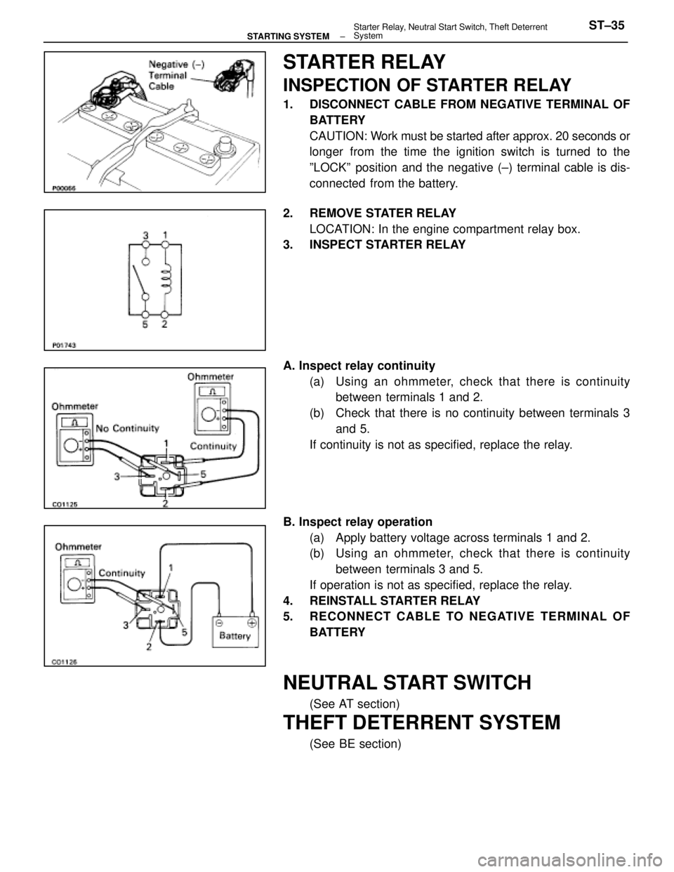
STARTER RELAY
INSPECTION OF STARTER RELAY
1. DISCONNECT CABLE FROM NEGATIVE TERMINAL OFBATTERY
CAUTION: Work must be started after approx. 20 seconds or
longer from the time the ignition switch is turned to the
ºLOCKº position and the negative (±) terminal cable is dis-
connected from the battery.
2. REMOVE STATER RELAY LOCATION: In the engine compartment relay box.
3. INSPECT STARTER RELAY
A. Inspect relay continuity
(a) Using an ohmmeter, check that there is continuitybetween terminals 1 and 2.
(b) Check that there is no continuity between terminals 3 and 5.
If continuity is not as specified, replace the relay.
B. Inspect relay operation (a) Apply battery voltage across terminals 1 and 2.
(b) Using an ohmmeter, check that there is continuitybetween terminals 3 and 5.
If operation is not as specified, replace the relay.
4. REINSTALL STARTER RELAY
5. RECONNECT CABLE TO NEGATIVE TERMINAL OF BATTERY
NEUTRAL START SWITCH
(See AT section)
THEFT DETERRENT SYSTEM
(See BE section)
±
STARTING SYSTEM Starter Relay, Neutral Start Switch, Theft Deterrent
SystemST±35
WhereEverybodyKnowsYourName
Page 2635 of 4087
YESNO
NOYES
YES
NO
OKNG
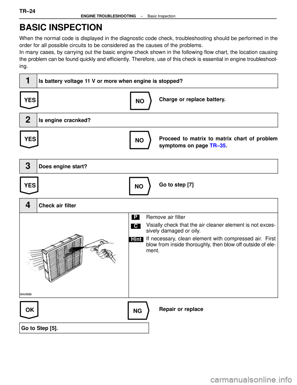
BASIC INSPECTION
When the normal code is displayed in the diagnostic code check, troubleshoot\
ing should be performed in the
order for all possible circuits to be considered as the causes of the pr\
oblems.
In many cases, by carrying out the basic engine check shown in the follo\
wing flow chart, the location causing
the problem can be found quickly and ef ficiently. Therefore, use of this check is essential in engine troubleshoot-
ing.
1Is battery voltage 11 V or more when engine is stopped?
Charge or replace battery.
2Is engine cracnked?
Proceed to matrix to matrix chart of problem
symptoms on page TR±35.
3Does engine start?
Go to step [7]
4Check air filter
C
Hint
PRemove air filter
Visially check that the air cleaner element is not exces-
sively damaged or oily.
If necessary, clean element with compressed air. First
blow from inside thoroughly, then blow off outside of ele-
ment.
Repair or replace
Go to Step [5].
TR±24±
ENGINE TROUBLESHOOTING Basic Inspection
WhereEverybodyKnowsYourName
Page 2871 of 4087
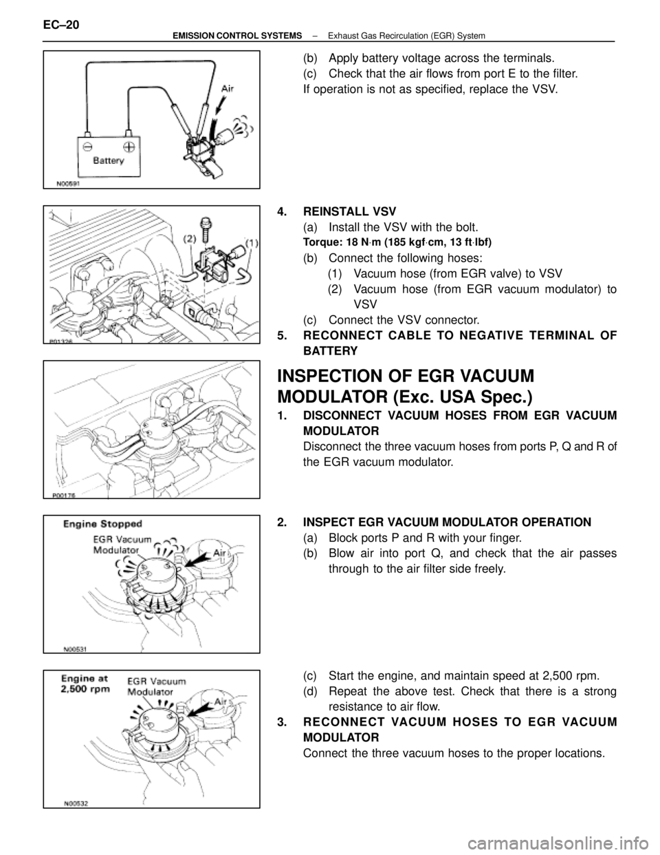
(b) Apply battery voltage across the terminals.
(c) Check that the air flows from port E to the filter.
If operation is not as specified, replace the VSV.
4. REINSTALL VSV (a) Install the VSV with the bolt.
Torque: 18 N Vm (185 kgf Vcm, 13 ft Vlbf)
(b) Connect the following hoses:
(1) Vacuum hose (from EGR valve) to VSV
(2) Vacuum hose (from EGR vacuum modulator) to VSV
(c) Connect the VSV connector.
5. RECONNECT CABLE TO NEGATIVE TERMINAL OF BATTERY
INSPECTION OF EGR VACUUM
MODULATOR (Exc. USA Spec.)
1. DISCONNECT VACUUM HOSES FROM EGR VACUUMMODULATOR
Disconnect the three vacuum hoses from ports P, Q and R of
the EGR vacuum modulator.
2. INSPECT EGR VACUUM MODULATOR OPERATION (a) Block ports P and R with your finger.
(b) Blow air into port Q, and check that the air passesthrough to the air filter side freely.
(c) Start the engine, and maintain speed at 2,500 rpm.
(d) Repeat the above test. Check that there is a strong resistance to air flow.
3. RECONNECT VACUUM HOSES TO EGR VACUUM MODULATOR
Connect the three vacuum hoses to the proper locations.
EC±20
±
EMISSION CONTROL SYSTEMS Exhaust Gas Recirculation (EGR) System
WhereEverybodyKnowsYourName
Page 2927 of 4087
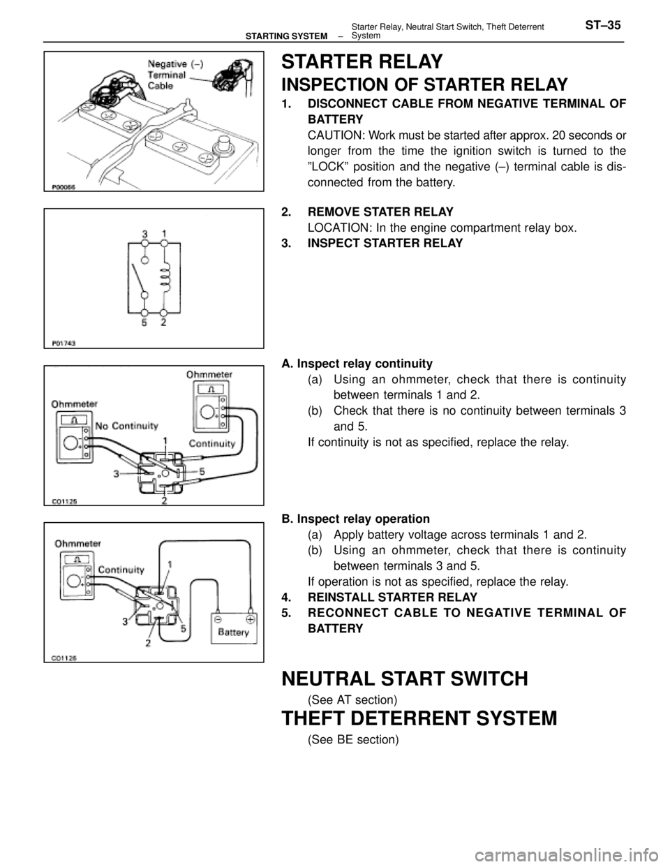
STARTER RELAY
INSPECTION OF STARTER RELAY
1. DISCONNECT CABLE FROM NEGATIVE TERMINAL OFBATTERY
CAUTION: Work must be started after approx. 20 seconds or
longer from the time the ignition switch is turned to the
ºLOCKº position and the negative (±) terminal cable is dis-
connected from the battery.
2. REMOVE STATER RELAY LOCATION: In the engine compartment relay box.
3. INSPECT STARTER RELAY
A. Inspect relay continuity
(a) Using an ohmmeter, check that there is continuitybetween terminals 1 and 2.
(b) Check that there is no continuity between terminals 3 and 5.
If continuity is not as specified, replace the relay.
B. Inspect relay operation (a) Apply battery voltage across terminals 1 and 2.
(b) Using an ohmmeter, check that there is continuitybetween terminals 3 and 5.
If operation is not as specified, replace the relay.
4. REINSTALL STARTER RELAY
5. RECONNECT CABLE TO NEGATIVE TERMINAL OF BATTERY
NEUTRAL START SWITCH
(See AT section)
THEFT DETERRENT SYSTEM
(See BE section)
±
STARTING SYSTEM Starter Relay, Neutral Start Switch, Theft Deterrent
SystemST±35
WhereEverybodyKnowsYourName
Page 3397 of 4087
YESNO
NOYES
YES
NO
OKNG
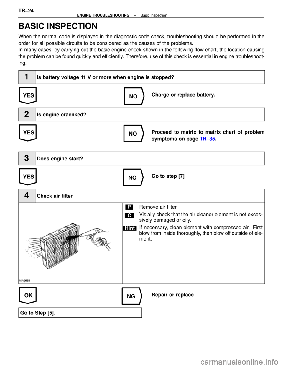
BASIC INSPECTION
When the normal code is displayed in the diagnostic code check, troubleshoot\
ing should be performed in the
order for all possible circuits to be considered as the causes of the pr\
oblems.
In many cases, by carrying out the basic engine check shown in the follo\
wing flow chart, the location causing
the problem can be found quickly and ef ficiently. Therefore, use of this check is essential in engine troubleshoot-
ing.
1Is battery voltage 11 V or more when engine is stopped?
Charge or replace battery.
2Is engine cracnked?
Proceed to matrix to matrix chart of problem
symptoms on page TR±35.
3Does engine start?
Go to step [7]
4Check air filter
C
Hint
PRemove air filter
Visially check that the air cleaner element is not exces-
sively damaged or oily.
If necessary, clean element with compressed air. First
blow from inside thoroughly, then blow off outside of ele-
ment.
Repair or replace
Go to Step [5].
TR±24±
ENGINE TROUBLESHOOTING Basic Inspection
WhereEverybodyKnowsYourName
Page 3609 of 4087
YESNO
NOYES
YES
NO
OKNG
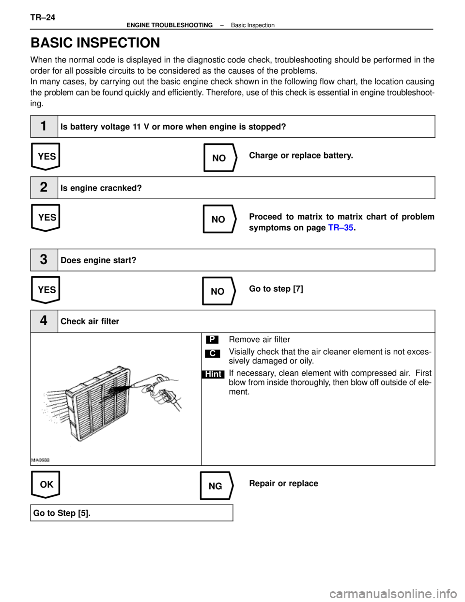
BASIC INSPECTION
When the normal code is displayed in the diagnostic code check, troubleshoot\
ing should be performed in the
order for all possible circuits to be considered as the causes of the pr\
oblems.
In many cases, by carrying out the basic engine check shown in the follo\
wing flow chart, the location causing
the problem can be found quickly and ef ficiently. Therefore, use of this check is essential in engine troubleshoot-
ing.
1Is battery voltage 11 V or more when engine is stopped?
Charge or replace battery.
2Is engine cracnked?
Proceed to matrix to matrix chart of problem
symptoms on page TR±35.
3Does engine start?
Go to step [7]
4Check air filter
C
Hint
PRemove air filter
Visially check that the air cleaner element is not exces-
sively damaged or oily.
If necessary, clean element with compressed air. First
blow from inside thoroughly, then blow off outside of ele-
ment.
Repair or replace
Go to Step [5].
TR±24±
ENGINE TROUBLESHOOTING Basic Inspection
WhereEverybodyKnowsYourName
Page 3928 of 4087

3
HOW TO USE THIS MANUAL
This manual provides information on the electrical circuits in on vehicles b\
y dividing
them into a circuit for each system.
The actual wiring of each system circuit is shown from the point where the \
power source
is received from the battery as far as each ground point. (All circuit di\
agrams are shown
with the switches in the OFF position.)
When troubleshooting any problem, first understand the operation of the circ\
uit where
the problem was detected (see System Circuit section), the power source supplying
power to that circuit (see Power Source section), and the ground points (s\
ee Ground
Points section). See the System Outline to understand the circuit opera\
tion.
When the circuit operation is understood, begin troubleshooting of the probl\
em circuit
to isolate the cause. Use Relay Location and Electrical Routing sections t\
o find each
part, junction block and wiring harness connectors, wiring harness and wiring\
harness
connectors, splice points, and ground points of each system circuit. Internal wirin\
g for
each junction block is also provided for better understanding of connection \
within a
junction block.
Wiring related to each system is indicated in each system circuit by arrows (from
, to ). When overall connections are required, see the Overall Wiring Diagram
at the end of this manual.
WhereEverybodyKnowsYourName