Page 689 of 4087

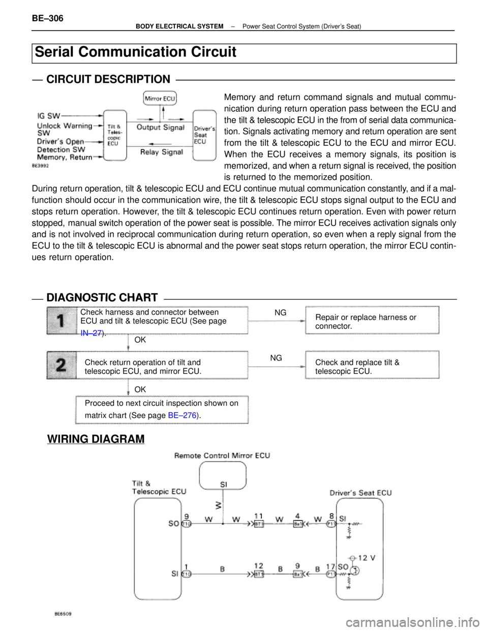
WIRING DIAGRAM
Check harness and connector between
ECU and tilt & telescopic ECU (See page
IN±27). NG
NG
OK
OK
Check return operation of tilt and
telescopic ECU, and mirror ECU. Repair or replace harness or
connector.
Check and replace tilt &
telescopic ECU.
Proceed to next circuit inspection shown on
matrix chart (See page BE±276).
Serial Communication Circuit
CIRCUIT DESCRIPTION
Memory and return command signals and mutual commu-
nication during return operation pass between the ECU and
the tilt & telescopic ECU in the from of serial data communica-
tion. Signals activating memory and return operation are sent
from the tilt & telescopic ECU to the ECU and mirror ECU.
When the ECU receives a memory signals, its position is
memorized, and when a return signal is received, the position
is returned to the memorized position.
During return operation, tilt & telescopic ECU and ECU continue mutual communi\
cation constantly, and if a mal-
function should occur in the communication wire, the tilt & telescopic ECU stops signal output to the ECU and
stops return operation. However, the tilt & telescopic ECU continues return operation. Even with power \
return
stopped, manual switch operation of the power seat is possible. The mirror ECU receives activation signals only
and is not involved in reciprocal communication during return operation, so\
even when a reply signal from the
ECU to the tilt & telescopic ECU is abnormal and the power seat stops retur\
n operation, the mirror ECU contin-
ues return operation.
DIAGNOSTIC CHARTDIAGNOSTIC CHART
BE±306±
BODY ELECTRICAL SYSTEM Power Seat Control System (Driver's Seat)
WhereEverybodyKnowsYourName
Page 698 of 4087
WIRING DIAGRAM
Terminal of ECU
No.SymbolTerminal NameNo.SymbolTerminal Name
P12±1SYSBPower SourceP12±10PFSWReclining Front Limit Switch
2SLSWSlide Limit Switch11SSRSSlide Sensor
3PVCCPosition Sensor Power Source12PBCLPassenger's Buckle Switch
4DOUT±±13RRSWReclining Rear Limit Switch
5SLDRSlide Switch (Back)14CHKCheck
6SLDFSlide Switch (Forward)15SGNDSensor Ground
7SLD+Slide Motor (Forward)16GNDGround
8+BPower Source17SLD±Slide Motor (Back)
9PRDCTension Reducer18
±
BODY ELECTRICAL SYSTEM Power Seat Control System (Passenger's Seat)BE±317
WhereEverybodyKnowsYourName
Page 705 of 4087
WIRING DIAGRAM
CIRCUIT INSPECTION
ECU Power Source Circuit
CIRCUIT DESCRIPTION
This circuit provides power for ECU operation and is also the power source f\
or the slide position sensor.
DIAGNOSTIC CHARTDIAGNOSTIC CHART
Check DOME fuse.NG
OK
NG NG
OK
OK Check for short in all the harness
and components connected to
DOME fuse. (See attached wir-
ing diagram).
Check voltage between terminals SYSB and
GND of ECU connector. Proceed to next circuit inspection
shown on matrix chart.
(See page
BE±319).
Check continuity between terminal GND of
ECU connector and body ground. Repair or replace harness or
connector.
Check and repair harness or connector
between ECU and battery.
BE±324±
BODY ELECTRICAL SYSTEM Power Seat Control System (Passenger's Seat)
WhereEverybodyKnowsYourName
Page 707 of 4087

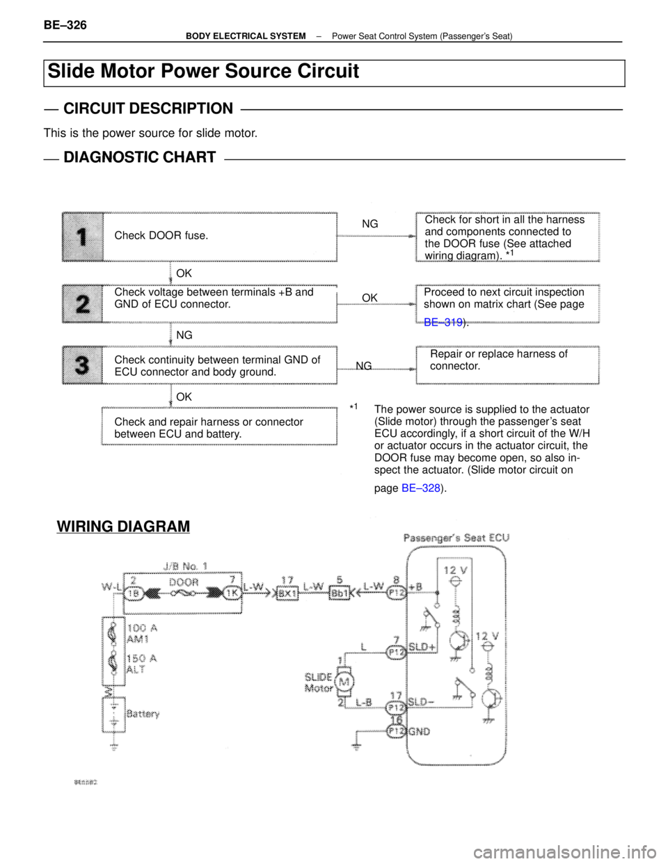
Check DOOR fuse.NG
OK
NG
OK NGOK Check for short in all the harness
and components connected to
the DOOR fuse (See attached
wiring diagram). *
1
Check voltage between terminals +B and
GND of ECU connector.
Proceed to next circuit inspection
shown on matrix chart (See page
BE±319
).
Check continuity between terminal GND of
ECU connector and body ground. Repair or replace harness of
connector.
Check and repair harness or connector
between ECU and battery. *
1The power source is supplied to the actuator
(Slide motor) through the passenger's seat
ECU accordingly, if a short circuit of the W/H
or actuator occurs in the actuator circuit, the
DOOR fuse may become open, so also in-
spect the actuator. (Slide motor circuit on
page
BE±328 ).
WIRING DIAGRAM
Slide Motor Power Source Circuit
CIRCUIT DESCRIPTION
This is the power source for slide motor.
DIAGNOSTIC CHARTDIAGNOSTIC CHART
BE±326±
BODY ELECTRICAL SYSTEM Power Seat Control System (Passenger's Seat)
WhereEverybodyKnowsYourName
Page 708 of 4087
OKNG
NGOK
OKNG
INSPECTION PROCEDURE
1Check DOOR fuse.
Check for short in all the harness components con-
nected to the DOOR fuse and repair them (See attached
wiring diagram). *1
2Check voltage between terminals +B and GND of ECU connector.
C
OK
PRemove passenger's seat ECU with connectors still
connected.
Measure voltage between terminals +B and GND of
ECU connector.
Voltage: 10 ± 14 V
Proceed to next circuit inspection shown on matrix chart
(See page BE±319).
3Check continuity between terminal GND of ECU connector and body ground.
C
OK
Measure resistance between terminal GND of ECU and
body ground.
Resistance: 1 � or less
Repair or replace harness or connector.
Check and repair harness or connector between
ECU and battery.
±
BODY ELECTRICAL SYSTEM Power Seat Control System (Passenger's Seat)BE±327
WhereEverybodyKnowsYourName
Page 709 of 4087
WIRING DIAGRAM
Slide Motor Circuit
CIRCUIT DESCRIPTION
The passenger's seat ECU control the slide motor.
DIAGNOSTIC CHARTDIAGNOSTIC CHART
Check slide motor.NG
NG
OK
OK Replace motor.
Repair or replace harness or
connector.
Check harness and connector between
ECU and motor (See page
IN±27).
Proceed to next circuit inspection shown
on matrix chart (See page BE±319).
BE±328±
BODY ELECTRICAL SYSTEM Power Seat Control System (Passenger's Seat)
WhereEverybodyKnowsYourName
Page 711 of 4087
WIRING DIAGRAM
Position Sensor Circuit
CIRCUIT DESCRIPTION
The position sensor senses movement of the seat and send
pulse signals to the ECU. The position sensor sends pulses
to the ECU in proportion to the amount of seat movement, as
shown in the diagram on the left.
If a malfunction occurs in a position sensor and a sensor sig-
nal is not input to the ECU even when the motor operates, the
ECU prohibits return operation.
DIAGNOSTIC CHARTDIAGNOSTIC CHART
Inspect the circuit which is malfunctioning.
Position sensor check.OK
NG
OK
OK NG
NG Proceed to next circuit inspection
shown on matrix chart (See page
BE±319
)
Replace position sensor.
Check position sensor.
Check harness and connectors between
ECU and position sensor (See page IN±27). Repair or replace harness or
connector.
Check and replace ECU.
BE±330±
BODY ELECTRICAL SYSTEM Power Seat Control System (Passenger's Seat)
WhereEverybodyKnowsYourName
Page 715 of 4087

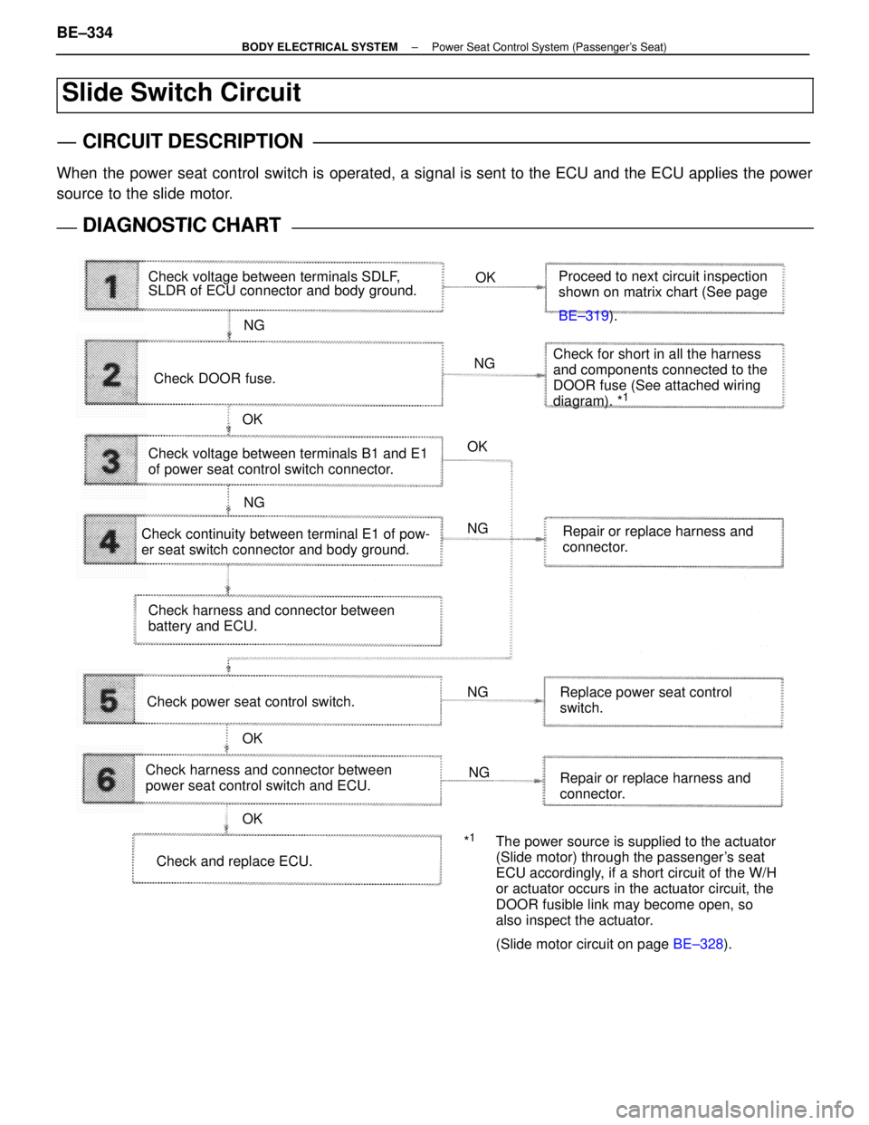
Slide Switch Circuit
CIRCUIT DESCRIPTION
When the power seat control switch is operated, a signal is sent to the ECU and the ECU applies the power
source to the slide motor.
DIAGNOSTIC CHARTDIAGNOSTIC CHART
Check voltage between terminals SDLF,
SLDR of ECU connector and body ground.OK
NG
OK OK
OK
OK NG
NG NG
NG
NG Proceed to next circuit inspection
shown on matrix chart (See page
BE±319
).
Check DOOR fuse. Check for short in all the harness
and components connected to the
DOOR fuse (See attached wiring
diagram). *
1
Check voltage between terminals B1 and E1
of power seat control switch connector.
Check continuity between terminal E1 of pow-
er seat switch connector and body ground. Repair or replace harness and
connector.
Check harness and connector between
battery and ECU.
Check power seat control switch. Replace power seat control
switch.
Check harness and connector between
power seat control switch and ECU. Repair or replace harness and
connector.
Check and replace ECU. *
1The power source is supplied to the actuator
(Slide motor) through the passenger's seat
ECU accordingly, if a short circuit of the W/H
or actuator occurs in the actuator circuit, the
DOOR fusible link may become open, so
also inspect the actuator.
(Slide motor circuit on page
BE±328).
BE±334±
BODY ELECTRICAL SYSTEM Power Seat Control System (Passenger's Seat)
WhereEverybodyKnowsYourName