Page 377 of 4087
ON±VEHICLE REPAIR
AT06Y±04
CAUTION: Work must be started after 90 seconds from
the time the ignition switch is turned to the ªLOCKº posi-
tion and the negative (±) terminal cable is disconnected
from the battery.
EXTENSION HOUSING
EXTENSION HOUSING REAR OIL SEAL
REPLACEMENT
AT0QW±01
1. DRAIN ATF
2. REMOVE FRONT EXHAUST PIPE AND HEAT INSULATOR
(See pages EG±204)
3. REMOVE PROPELLER SHAFT (See pages PR±6)
4. REMOVE TRANSMISSION OUTPUT FLANGE
(a) Using a hammer and chisel, loosen the staked part of the nut.
HINT: Shift the shift lever to the P position.
(b) Using SST, remove the nut.
SST 09060±20100
(c) Tap the output flange with a plastic hammer to remove it and 2 washers.
(d) Using a screwdriver, remove the oil seal from the output flange.
5. REMOVE EXTENSION HOUSING REAR OIL SEAL Using SST, remove the oil seal.
SST 09308±00010
AT±14
±
A304E (1UZ±FE) AUTOMATIC TRANSMISSION EXTENSION HOUSING
WhereEverybodyKnowsYourName
Page 386 of 4087
ASSEMBLY REMOVAL AND INSTALLATION
AT0GJ±02
Remove and install the parts, as shown.
NOTICE: Work must be started after 90 seconds from the time the ignition switch i\
s turned to the ªLOCKº
position and the negative (±) terminal cable is disconnected from t\
he battery.
±
A304E (1UZ±FE) AUTOMATIC TRANSMISSION ASSEMBLY REMOVAL AND INSTALLATIONAT±23
WhereEverybodyKnowsYourName
Page 398 of 4087
MIRROR
Outside Rear View Mirror
COMPONENTS
REMOVAL AND INSTALLATION OF
OUTSIDE REAR VIEW MIRROR
HINT: Install the mirror by following the removal sequence
in reverse.
1. DISCONNECT BATTERY CABLE FROM NEGATIVE TERMINAL
CAUTION: Work must be started after approx. 20 se-
conds or longer from the time the ignition switch is
turned to the ºLOCKº position and the negative (±) termi-
nal cable is disconnected from the battery.
2. REMOVE DOOR TRIM UPPER PANEL Removal: (See step 5 on page BO±34)
Installation: (See step 16 on page BO±40)
3. REMOVE MIRROR (a) Connect the connector, install the mirror with two bolts.
(b) Connect the connector, install the speaker with twobolts.
BO±42
±
BODY Mirror (Outside Rear View Mirror)
WhereEverybodyKnowsYourName
Page 441 of 4087
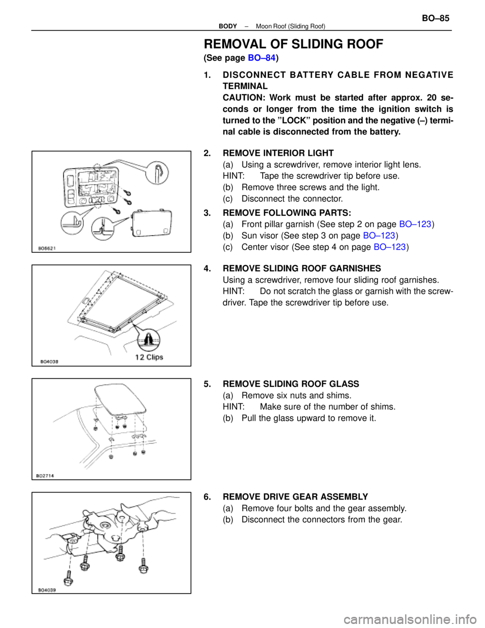
REMOVAL OF SLIDING ROOF
(See page BO±84)
1. DISCONNECT BATTERY CABLE FROM NEGATIVE TERMINAL
CAUTION: Work must be started after approx. 20 se-
conds or longer from the time the ignition switch is
turned to the ºLOCKº position and the negative (±) termi-
nal cable is disconnected from the battery.
2. REMOVE INTERIOR LIGHT (a) Using a screwdriver, remove interior light lens.
HINT: Tape the screwdriver tip before use.
(b) Remove three screws and the light.
(c) Disconnect the connector.
3. REMOVE FOLLOWING PARTS: (a) Front pillar garnish (See step 2 on page BO±123)
(b) Sun visor (See step 3 on page BO±123)
(c) Center visor (See step 4 on page BO±123)
4. REMOVE SLIDING ROOF GARNISHES Using a screwdriver, remove four sliding roof garnishes.
HINT: Do not scratch the glass or garnish with the screw-
driver. Tape the screwdriver tip before use.
5. REMOVE SLIDING ROOF GLASS (a) Remove six nuts and shims.
HINT: Make sure of the number of shims.
(b) Pull the glass upward to remove it.
6. REMOVE DRIVE GEAR ASSEMBLY (a) Remove four bolts and the gear assembly.
(b) Disconnect the connectors from the gear.
±
BODY Moon Roof (Sliding Roof)BO±85
WhereEverybodyKnowsYourName
Page 465 of 4087
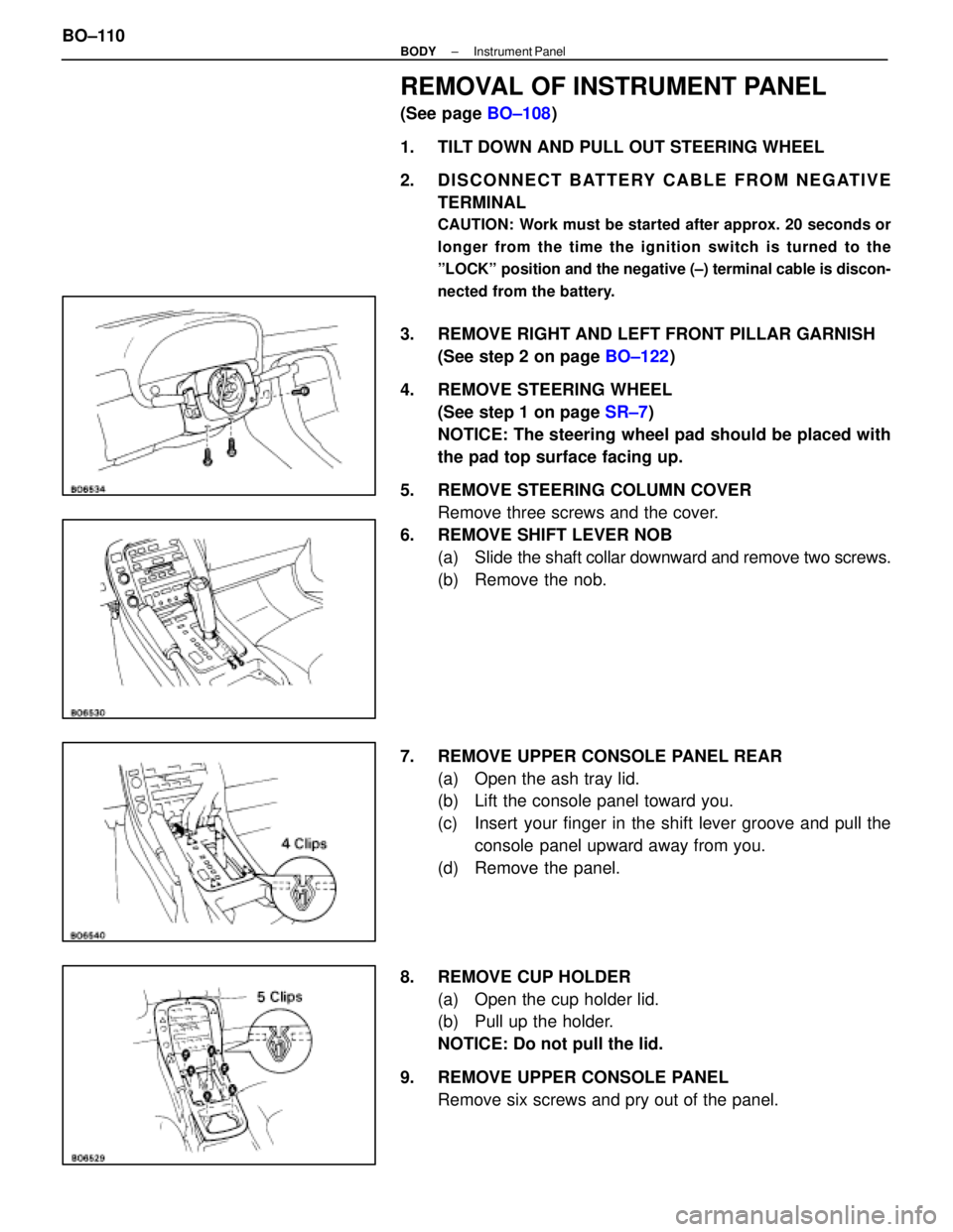
REMOVAL OF INSTRUMENT PANEL
(See page BO±108)
1. TILT DOWN AND PULL OUT STEERING WHEEL
2. DISCONNECT BATTERY CABLE FROM NEGATIVE TERMINAL
CAUTION: Work must be started after approx. 20 seconds or
longer from the time the ignition switch is turned to the
ºLOCKº position and the negative (±) terminal cable is discon-
nected from the battery.
3. REMOVE RIGHT AND LEFT FRONT PILLAR GARNISH(See step 2 on page BO±122)
4. REMOVE STEERING WHEEL (See step 1 on page SR±7)
NOTICE: The steering wheel pad should be placed with
the pad top surface facing up.
5. REMOVE STEERING COLUMN COVER Remove three screws and the cover.
6. REMOVE SHIFT LEVER NOB (a) Slide the shaft collar downward and remove two screws.
(b) Remove the nob.
7. REMOVE UPPER CONSOLE PANEL REAR (a) Open the ash tray lid.
(b) Lift the console panel toward you.
(c) Insert your finger in the shift lever groove and pull theconsole panel upward away from you.
(d) Remove the panel.
8. REMOVE CUP HOLDER (a) Open the cup holder lid.
(b) Pull up the holder.
NOTICE: Do not pull the lid.
9. REMOVE UPPER CONSOLE PANEL Remove six screws and pry out of the panel.
BO±110
±
BODY Instrument Panel
WhereEverybodyKnowsYourName
Page 496 of 4087
ExampleGENERAL INFORMATION
HANDLING PRECAUTIONS
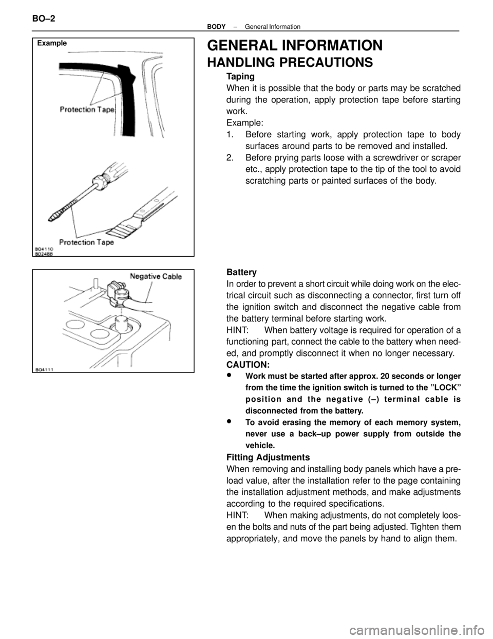
Taping
When it is possible that the body or parts may be scratched
during the operation, apply protection tape before starting
work.
Example:
1. Before starting work, apply protection tape to bodysurfaces around parts to be removed and installed.
2. Before prying parts loose with a screwdriver or scraper etc., apply protection tape to the tip of the tool to avoid
scratching parts or painted surfaces of the body.
Battery
In order to prevent a short circuit while doing work on the elec-
trical circuit such as disconnecting a connector, first turn off
the ignition switch and disconnect the negative cable from
the battery terminal before starting work.
HINT: When battery voltage is required for operation of a
functioning part, connect the cable to the battery when need-
ed, and promptly disconnect it when no longer necessary.
CAUTION:
wWork must be started after approx. 20 seconds or longer
from the time the ignition switch is turned to the ºLOCKº
position and the negative (±) terminal cable is
disconnected from the battery.
wTo avoid erasing the memory of each memory system,
never use a back±up power supply from outside the
vehicle.
Fitting Adjustments
When removing and installing body panels which have a pre-
load value, after the installation refer to the page containing
the installation adjustment methods, and make adjustments
according to the required specifications.
HINT: When making adjustments, do not completely loos-
en the bolts and nuts of the part being adjusted. T ighten them
appropriately, and move the panels by hand to align them.
BO±2
±
BODY General Information
WhereEverybodyKnowsYourName
Page 502 of 4087
SRS AIRBAG
(See page AB±2)
The LEXUS SC300 is equipped with an SRS (Supplemental Restraint System)\
airbag.
Failure to carry out service operations in the correct sequence could cause the airbag system to deploy,
possibly leading to a serious accident.
When removal or installation of airbag parts and the yellow wire harness\
and connector for the airbag is
necessary, refer to the precautionary notices in the AB section before performing\
the operation.
�Work must be started after 20 seconds or longer from the time the ignition switch is set to the LOCK
position and the negative (±) terminal cable is disconnected from the batte\
ry.
(The airbag system is equipped with a back±up power source so that if wor\
k is started within 20 se-
conds of disconnecting the negative (±) terminal cable of the batte\
ry, the airbag may be deployed.
�To avoid erasing the memory of each memory system, never use a back±up power supply from
outside the vehicle.
�Before repairs, remove the airbag sensors if shocks are likely to be applied t\
o the sensors during
repaires.
�The front airbag sensor set bolt has been anti±rust treated. When the\
sensor is removed, always
replace the set bolt with a new one.
�If the front airbag sensors, center airbag sensor or steering wheel pad ha\
ve been dropped, or if there
are cracks, dents or other defects in the case, bracket or connector, replace them with new ones.
�Never use airbag parts from another vehicle. When replacing parts, repla\
ce them with new parts.
�Do not expose the front airbag sensors, center airbag sensor or steering w\
heel pad directly to hot air
or flames.
�The airbag system's wire harness is integrated with the cowl wire harness assembly. The wires for the
airbag wire harness are encased in a yellow corrugated tube. All the connector\
s for the system are
also a standard yellow color. If the airbag system wire harness becomes disconnected or the
connector becomes broken due to an accident, etc., repair or replace it as shown \
on page AB±20.
�The steering wheel must be fitted correctly to the steering column with the\
spiral cable at the neutral
position; otherwise, cable disconnection and other troubles may result. \
Refer to page AB±14 of this
manual concerning correct steering wheel installation.
�When removing the steering wheel pad or handling a new steering wheel pad, i\
t should be placed with
the pad top surface facing up. In this case, the twin±lock type connector lock lever should be in the
locked state and care should be taken to place it so the connector will not be damaged. (\
Storing the
pad with its metallic surface up may lead to a serious accident if the a\
irbag inflates for some reason.)
�Grease should not be applied to the steering wheel pad and the pad should not \
be cleaned with
detergents of any kind.
�Store the steering wheel pad where the ambient temperature remains below 93 �C (200 �F), without
high humidity and away from electrical noise.
�Information labels are attached to the periphery of the airbag component\
s. Follow the notices.
�When the ignition switch is at ACC or ON and the airbag warning light remains on, the cent\
er airbag
sensor assembly has detected a malfunction code. (See page AB±30).
BO±8
±
BODY General Information
WhereEverybodyKnowsYourName
Page 539 of 4087
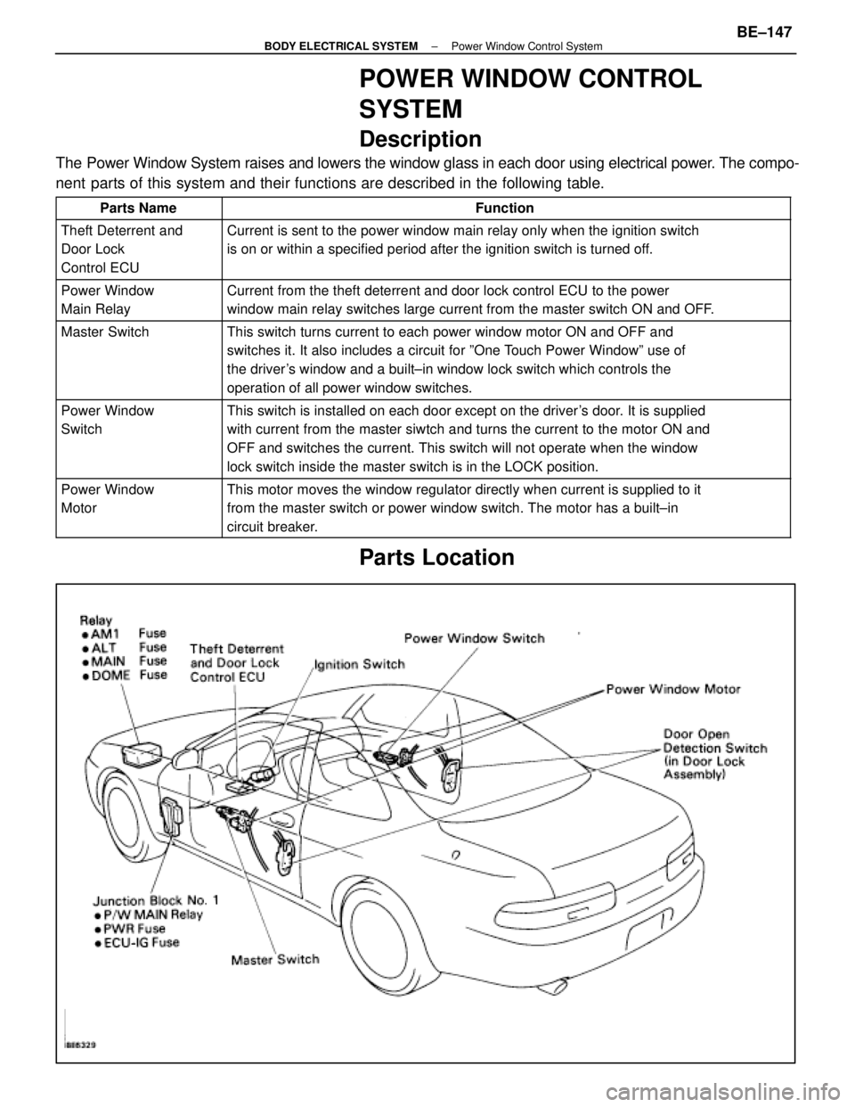
POWER WINDOW CONTROL
SYSTEM
Description
The Power Window System raises and lowers the window glass in each door usi\
ng electrical power. The compo-
nent parts of this system and their functions are described in the following\
table.
Parts NameFunction
Theft Deterrent and
Door Lock
Control ECUCurrent is sent to the power window main relay only when the ignition sw\
itch
is on or within a specified period after the ignition switch is turned o\
ff.
Power Window
Main RelayCurrent from the theft deterrent and door lock control ECU to the power
window main relay switches large current from the master switch ON and O\
FF.
Master SwitchThis switch turns current to each power window motor ON and OFF and
switches it. It also includes a circuit for ºOne Touch Power Windowº use of
the driver's window and a built±in window lock switch which controls the
operation of all power window switches.
Power Window
SwitchThis switch is installed on each door except on the driver's door. It is supplied
with current from the master siwtch and turns the current to the motor O\
N and
OFF and switches the current. This switch will not operate when the wind\
ow
lock switch inside the master switch is in the LOCK position.
Power Window
MotorThis motor moves the window regulator directly when current is supplied \
to it
from the master switch or power window switch. The motor has a built±\
in
circuit breaker.
Parts Location
±
BODY ELECTRICAL SYSTEM Power Window Control SystemBE±147
WhereEverybodyKnowsYourName