Page 748 of 1640

Starting Syste m
Starter Tes t
NOTE : Th e ai r temperatur e mus t b e betwee n 5 9 an d
100° F (1 5 an d 38°C ) befor e testing .
Recommende d Procedure :
• Us e a starte r syste m tester .
• Connec t an d operat e th e equipmen t i n accor -
danc e wit h manufacturer' s instructions .
Alternate Procedure :
• Us e th e followin g equipment :
- Ammeter, 0-400 A
- Voltmeter , 0-2 0 V (accurat e withi n 0. 1
volt )
- Tachometer , 0—120 0 rp m
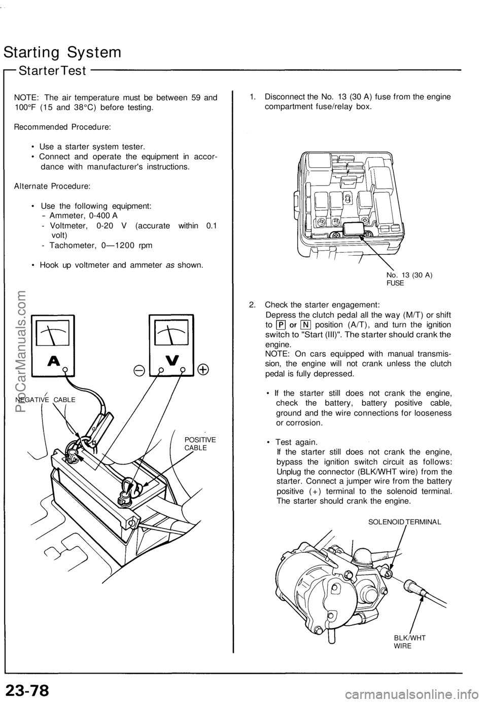
• Hoo k u p voltmete r an d ammete r as shown .
NEGATIV E CABL E
POSITIV ECABLE
1. Disconnec t th e No . 1 3 (3 0 A ) fus e fro m th e engin e
compartmen t fuse/rela y box .
No. 1 3 (3 0 A )FUS E
2. Chec k th e starte r engagement :
Depres s th e clutc h peda l al l th e wa y (M/T ) o r shif t
to positio n (A/T) , an d tur n th e ignitio n
switch to "Star t (III)" . Th e starte r shoul d cran k th e
engine .
NOTE : O n car s equippe d wit h manua l transmis -
sion , th e engin e wil l no t cran k unles s th e clutc h
peda l i s full y depressed .
• I f th e starte r stil l doe s no t cran k th e engine ,
chec k th e battery , batter y positiv e cable ,
groun d an d th e wir e connection s fo r loosenes s
o r corrosion .
• Tes t again .
I f th e starte r stil l doe s no t cran k th e engine ,
bypas s th e ignitio n switc h circui t a s follows :
Unplu g th e connecto r (BLK/WH T wire ) fro m th e
starter . Connec t a jumpe r wir e fro m th e batter y
positiv e (+ ) termina l t o th e solenoi d terminal .
Th e starte r shoul d cran k th e engine .
SOLENOI D TERMINA L
BLK/WHTWIRE
ProCarManuals.com
Page 761 of 1640

Ignition Syste m
Idle Spee d Inspectio n
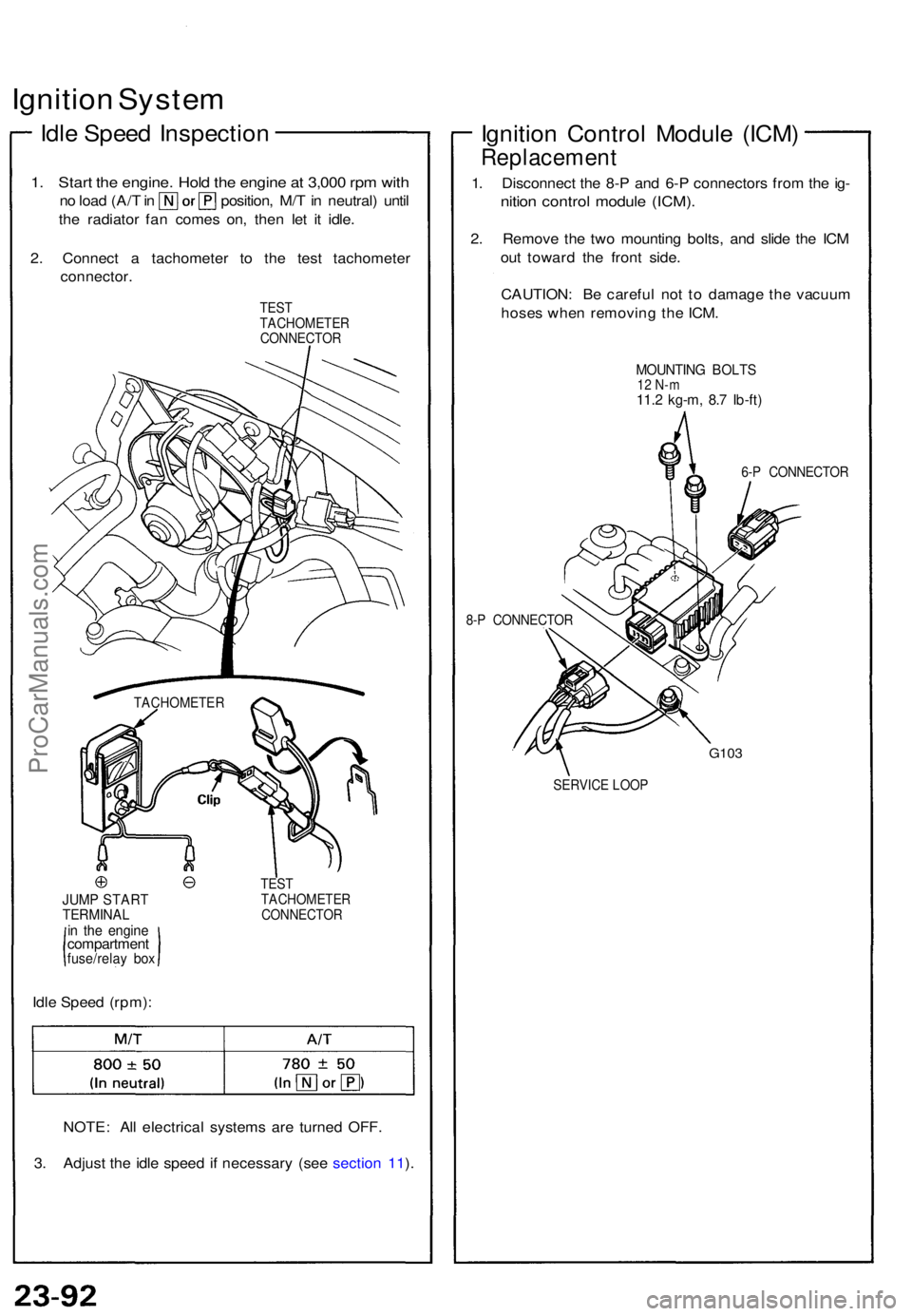
1. Star t th e engine . Hol d th e engin e a t 3,00 0 rp m wit h
no loa d (A/ T in position , M/ T in neutral ) unti l
th e radiator fan come s on , the n le t i t idle .
2 . Connec t a tachomete r t o th e tes t tachomete r
connector .
TEST
TACHOMETE R
CONNECTO R
JUMP STAR TTERMINA Lin th e engin ecompartmen tfuse/relay bo x
Idle Spee d (rpm) :
TEST
TACHOMETE R
CONNECTO R
NOTE: Al l electrica l system s ar e turne d OFF .
3 . Adjus t th e idl e spee d i f necessar y (se e sectio n 11 ).
Ignitio n Contro l Modul e (ICM )
Replacemen t
1. Disconnec t th e 8- P an d 6- P connector s fro m th e ig -
nitio n contro l modul e (ICM) .
2. Remov e th e tw o mountin g bolts , an d slid e th e IC M
ou t towar d th e fron t side .
CAUTION : B e carefu l no t t o damag e th e vacuu m
hose s whe n removin g th e ICM .
MOUNTIN G BOLT S12 N- m11.2 kg-m , 8. 7 Ib-ft )
6-P CONNECTO R
8- P CONNECTO R
G103
SERVIC E LOO P
TACHOMETE
R
ProCarManuals.com
Page 768 of 1640
(From pag e 23-100 )
Turn th e ignitio n switc h off .
Chec k fus e No . 2 (1 5 A) .
I s th e fus e OK ?
Disconnec t th e 4- P connecto r
fro m th e alternator .
Tur n th e ignitio n switc h on .
Chec k fo r voltag e in th e YE L wir e
a t th e IG termina l o f th e 4- P con -
nector .
I s ther e batter y voltage ?
Groun d th e WHT/BL U wire at th e
L termina l o f th e 4- P connector .
Doe s th e chargin g syste m ligh t
com e on ?
Perfor m alternator/regulato r tes t(see pag e 23-102 ).
Replac e th e fuse .
L (WHT/BLU )
IG (YEL )
View fro m
termina l sid e
Repai r ope n i n th e YE L wire .
Check fo r a blow n chargin g
syste m ligh t bulb . I f th e bul b is
OK . repai r ope n in th e WHT/BL U
wire.
ProCarManuals.com
Page 769 of 1640
Charging System
Troubleshooting
Alternator/Regulator Test
Use the SUN VAT-40 (or equivalent) tester.
2. Attach the negative tester cable and the voltmeter
negative lead to the top of the intake manifold.
LOAD ADJUSTER
(CARBON PILE)
FULL FIELD
LEAD (BLU)
VOLTMETER
NEGATIVE
LEAD (BLK)
VOLT
SELECTOR
FIELD
SELECTOR
INDUCTIVE
PICK-UP
(GRN)
POSITIVE
CABLE (RED)
NEGATIVE
CABLE (BLK)
VOLTMETER
POSITIVE
LEAD (RED)
1. Attach the positive tester cable and the voltmeter
positive lead to the jump start terminal in the
engine compartment fuse/relay box.
POSITIVE CABLE
VOLTMETER
POSITIVE LEAD
JUMP
START
TERMINAL
- ENGINE COMPARTMENT
FUSE/RELAY BOX
VOLTMETER
NEGATIVE LEAD
NEGATIVE CABLE
NEGATIVE MARK
3. Attach the inductive pick-up to the B terminal wire
of the alternator with its arrow pointing away from
the terminal.
NOTE: The arrow must point away from the B
terminal.
INDUCTIVE PICK-UP
ARROW
ALTERNATOR
B TERMINAL
ALTERNATOR
TEST SELECTOR
SWITCHProCarManuals.com
Page 786 of 1640
Gauge Assembly
Gauge/Terminal Location Index
SRS components are located in this area. Review the SRS component locations, precautions, and procedures in the SRS
section (24) before performing repairs or service.
SPEEDOMETER:
Indicates 60 mph [60km/h] at 1.026 [637]
rpm of the vehicle speed sensor (VSS).
FUEL GAUGE: Gauge test, page 23-134 Sending Unit Test, page 23-135
VOLTAGE METER:
If, with the No. 5 (15 A) fuse
and other gauges
OK, the pointer of the
voltage meter does not move at all,
replace the voltage
meter.
SAFETY INDICATOR SYSTEM:
See page 23-145 ('93-'96) ('91-'92)A/T GEAR POSITION
INDICATOR SYSTEM:
See page 23-156 ENGINE OIL PRESSURE
GAUGE:
Test page 23-137
ENGINE COOLANT TEMPERATURE (ECT) GAUGE:
Gauge Test, page 23-136 Sender Test, page 23-136
TACHOMETER:
Indicates 100 rpm at 300 pulses per minute
of the igniter unit.ProCarManuals.com
Page 792 of 1640

NOTE: A shor t t o groun d i n th e OR N wir e ca n b e cause d b y a shor t i n an y componen t connecte d t o it .
Vehicl e Spee d Senso r (VSS ) Tes t
Speedomete r doe s no t work.
Inspec t No . 5 (1 5 A ) fus e in th e
under-das h fus e bo x befor e
testing .
Disconnec t th e 3- P connecto r
fro m th e VSS .
Turn th e ignitio n switc h O N (II) .
Measur e voltag e betwee n th e YE L
wir e termina l an d th e BL K wir e
termina l i n th e harnes s sid e o f th e
3- P connector .
I s ther e batter y voltage ?
Measur e voltag e betwee n th e
OR N an d th e BL K wir e terminals .
I s ther e abou t 5 V ?
(T o page 23-132 ) Vie
w fro m
termina l sid e
, BL K 3- P CONNECTO R
VSS
Is ther e continuity ?
Repai r ope n in th e OR N wir e o r
shor t t o bod y ground .Repair ope n betwee nthe VS S an d groun dG101.
Repai r ope n in th e YE L wir e be -
twee n th e VS S an d under-das h
fuse box .
Chec k fo r continuit y betwee n th eBLK termina l an d bod y ground .
ProCarManuals.com
Page 826 of 1640
UNDER-HOOD FUSE/RELAY BOX
UNDER-HOOD RELAY BOX A
DIMMER RELAY
Test, page 23-189
TAILLIGHT RELAYTest, page 23-190
('94-'96) ('91-'93) LEFT HEADLIGHT
RETRACTOR CUT RELAY
Test page 23-190 ('94-'96) ('91-'93)
RIGHT HEADLIGHTRETRACTOR CUT RELAYTest, page 23-190 ('94-'96) ('91-'93)
HEADLIGHT RELAY
Test, page 23-189
RIGHT HEADLIGHT
RETRACTOR RELAY
Test page 23-190
('94-'96) ('91-'93)
RIGHT HEADLIGHT
RETRACTOR MOTOR
Test, page 23-188
Replacement, page
23-186
RIGHT DAYTIME RUNNING
LIGHT (Canada)
Replacement, page, 23-194 HEADLIGHTS
Adjustment, page 23-192
Replacement page 23-163
LEFT DAYTIME RUNNING LIGHT (Canada)
Replacement, page 23-194
LEFT HEADLIGHT
RETRACTOR MOTOR
Test, page 23-186 Replacement, page 23-186 LEFT HEADLIGHT
RETRACTOR RELAY
Test, page 23-190
('94-'96) ('91-'93)ProCarManuals.com
Page 836 of 1640
Lighting System
Retractor Motor Replacement
CAUTION:
• Halogen headlights can become very hot in use; do
not touch them or the attaching hardware immediately
after they have been turned off.
• Do not try to replace or clean headlights with the lights
on.
1. Remove the No. 42 (15 A) and No. 43 (15 A) fuses
from the under-hood fuse/relay box.
No. 43
(15A)
FUSE
No. 42
(15A)
FUSE
UNDER-HOOD FUSE/RELAY BOX
2. Turn the knob clockwise to raise the headlight.
CAP
KNOB
3. Remove the two caps, four screws, and cowl clips.
COWL CLIP
CAP
SCREW
4. Slide the headlight housing forward and up.
NOTE: Be careful not to damage the front bumper
or the headlight housing.
HEADLIGHT HOUSING
PROTECTIVE TAPE
5. Disconnect the 6-P connector from the headlight
unit.
6-P CONNECTOR
HEADLIGHT UNIT
6. Remove the four mounting bolts, then remove the
unit.
MOUNTING
BOLTSProCarManuals.com