1991 ACURA NSX wheel torque
[x] Cancel search: wheel torquePage 496 of 1640
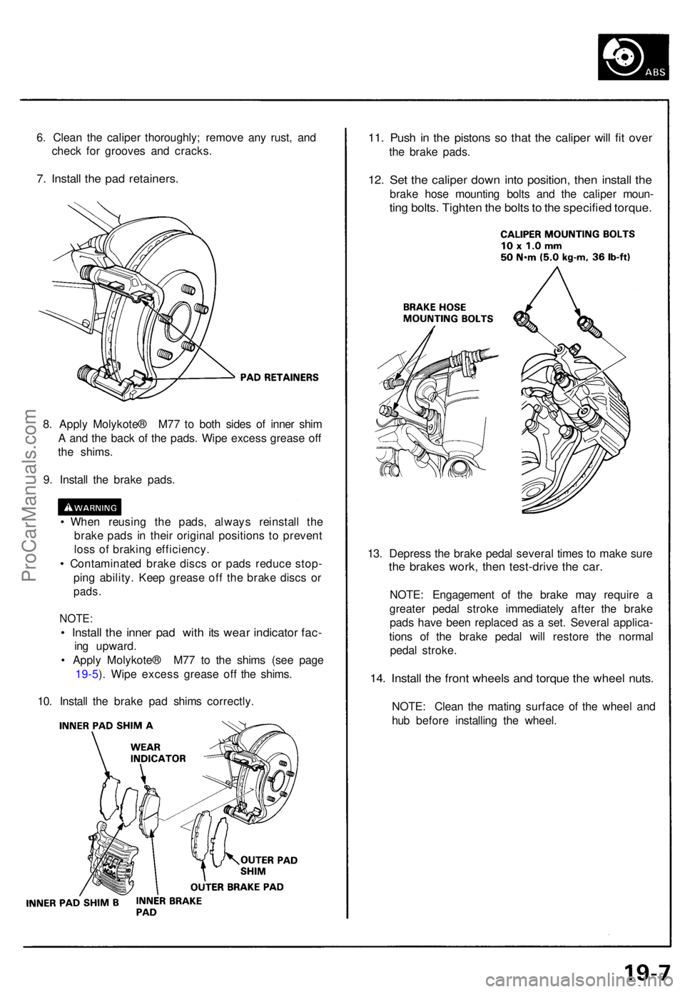
6. Clea n th e calipe r thoroughly ; remov e an y rust , an d
chec k fo r groove s an d cracks .
7. Instal l th e pa d retainers .
11. Pus h i n th e piston s s o tha t th e calipe r wil l fi t ove r
the brak e pads .
12. Se t th e calipe r dow n int o position , the n instal l th e
brak e hos e mountin g bolt s an d th e calipe r moun -
ting bolts . Tighte n th e bolt s to th e specifie d torque .
8. Appl y Molykote ® M7 7 t o bot h side s o f inne r shi m
A an d th e bac k o f th e pads . Wip e exces s greas e of f
th e shims .
9 . Instal l th e brak e pads .
• Whe n reusin g th e pads , alway s reinstal l th e
brak e pad s i n thei r origina l position s t o preven t
los s o f brakin g efficiency .
• Contaminate d brak e disc s o r pad s reduc e stop -
pin g ability . Kee p greas e of f th e brak e disc s o r
pads .
NOTE :
• Instal l th e inne r pa d wit h it s wea r indicato r fac -
ing upward .
• Appl y Molykote ® M7 7 t o th e shim s (se e pag e
19-5 ). Wip e exces s greas e of f th e shims .
10 . Instal l th e brak e pa d shim s correctly . 13
. Depres s th e brak e peda l severa l time s t o mak e sur e
the brake s work , the n test-driv e th e car .
NOTE : Engagemen t of the brak e ma y requir e a
greate r peda l strok e immediatel y afte r th e brak e
pad s hav e bee n replace d a s a set . Severa l applica -
tion s of the brak e peda l wil l restor e th e norma l
peda l stroke .
14. Instal l th e fron t wheel s an d torqu e th e whee l nuts .
NOTE : Clea n th e matin g surfac e o f th e whee l an d
hu b befor e installin g th e wheel .
ProCarManuals.com
Page 507 of 1640
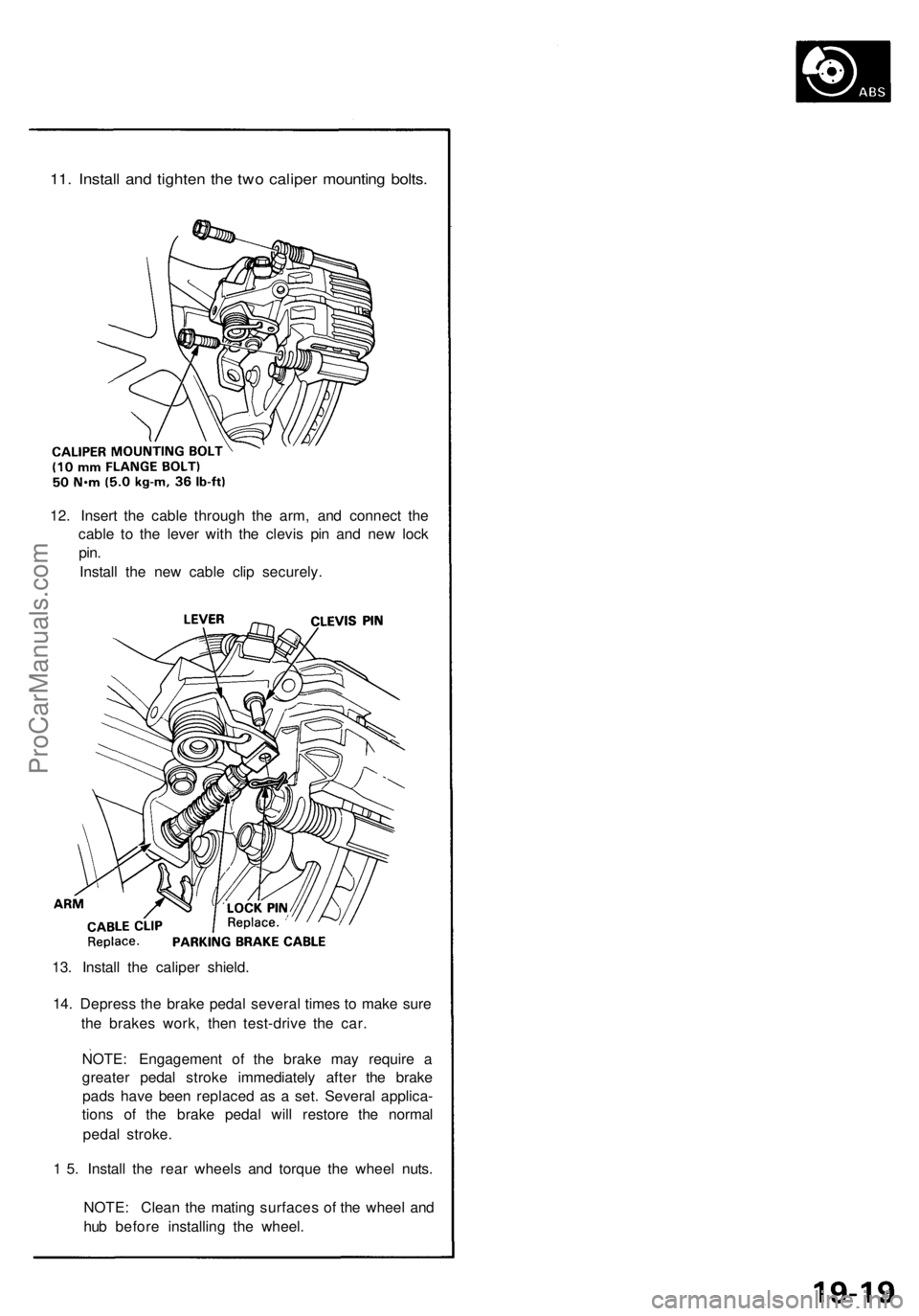
11. Install and tighten the two caliper mounting bolts.
12. Insert the cable through the arm, and connect the
cable to the lever with the clevis pin and new lock
pin.
Install the new cable clip securely.
13. Install the caliper shield.
14. Depress the brake pedal several times to make sure
the brakes work, then test-drive the car.
NOTE: Engagement of the brake may require a
greater pedal stroke immediately after the brake
pads have been replaced as a set. Several applica-
tions of the brake pedal will restore the normal
pedal stroke.
1 5. Install the rear wheels and torque the wheel nuts.
NOTE: Clean the mating surfaces of the wheel and
hub before installing the wheel.ProCarManuals.com
Page 998 of 1640
Engine Removal/Installation
(cont'd)
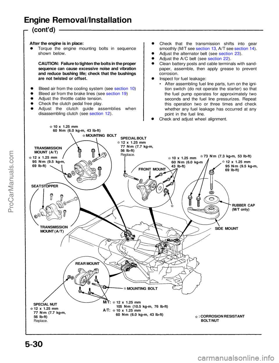
Torque the engine mounting bolts in sequenceshown below.
CAUTION: Failure to tighten the bolts in the proper
sequence can cause excessive noise and vibration
and reduce bushing life; check that the bushings
are not twisted or offset.
Bleed air from the cooling system (see section 10)
Bleed air from the brake lines (see section 19)
Adjust the throttle cable tension.
Check the clutch pedal free play.
Adjust the clutch guide assemblies when
disassembling clutch (see section 12). Check that the transmission shifts into gear
smoothly (M/T see section 13, A/T see section 14).
Adjust the alternator belt (see section 23).
Adjust the A/C belt (see section 22).
Clean battery posts and cable terminals with sand-
paper, assemble, then apply grease to prevent
corrosion.
Inspect for fuel leakage:
• After assembling fuel line parts, turn on the igni- tion switch (do not operate the starter) so that
the fuel pump operates for approximately two seconds and the fuel line pressurizes. Repeat
this operation two or three times and check whether any fuel leakage has occurred at any
point in the fuel line.
Check and adjust wheel alignment.
10 x
1.25
mm
60 N .
m (6.0 kg-m, 43 Ib-ft)
MOUNTING BOLT SPECIAL BOLT
12 x
1.25
mm
77 N .
m
(7.7 kg-m,
56 Ib-ft)
Replace.
10 x
1.25
mm
60 N .
m
(6.0 kg-m
43 Ib-ft) 73 N.m (7.3 kg-m, 53 Ib-ft)
12 x
1.25
mm
95 N .
m
(9.5 kg-m,
69 Ib-ft)
RUBBER CAP
(M/T only)
SIDE MOUNT
: CORROSION RESISTANT
BOLT/NUT
12 x
1.25
mm
105 N .
m (10.5 kg-m, 76 Ib-ft)
10 x
1.25
mm
60 N .
m (6.0 kg-m, 43 Ib-ft) MOUNTING BOLT FRONT MOUNT
TRANSMISSION
MOUNT (A/T)
12 x
1.25
mm
95 N .
m
(9.5 kg-m,
69 Ib-ft)
SEAT STOPPER
TRANSMISSION
MOUNT (A/T)
REAR MOUNT
SPECIAL NUT
12 x
1.25
mm
77 N .
m
(7.7 kg-m,
56 Ib-ft)
Replace.
M/T:
A/T:
After the engine is in place:ProCarManuals.com
Page 1165 of 1640
Description
The automatic transmission is a combination of a 3-element torque converter and a triple-shaft electronically controlled
automatic transmission which provides 4 speeds forward and 1 in reverse. The entire unit is positioned in line with the
engine.
TORQUE CONVERTER, GEARS AND CLUTCHES
The torque converter consists of a pump, turbine and stator, assembled in a single unit.
They are connected to the engine crankshaft so they turn together as a unit as the engine turns.
Around the outside of the torque converter is a ring gear which meshes with the starter pinion when the engine is being
started. The entire torque converter assembly serves as a flywheel while transmitting power to the transmission mainshaft.
The transmission has three parallel shafts, the mainshaft, the countershaft, and the secondary shaft. The mainshaft is
in line with the engine crankshaft.
The mainshaft includes the clutches for 1st, and 4th, and gears for 3rd, 4th, Reverse and 1st (3rd gear is integral with
the mainshaft, while reverse gear is integral with 4th gear).
The countershaft includes the clutches for 1st-Hold and 3rd, and gears for 2nd, 3rd, 4th, Reverse and 1st.
The secondary shaft includes the 2nd clutch and gears for 2nd and 3rd.
The 4th and reverse gears can be locked to the countershaft at its center, providing 4th gear or Reverse, depending on
which way the selector is moved.
The gears on the mainshaft and secondary shaft are in constant mesh with those on the countershaft.
When certain combinations of gears in the transmission are engaged by clutches, power is transmitted from the main-
shaft to the countershaft to provide , , , and
ELECTRONIC CONTROL
The electronic control system consists of the Transmission Control Module (TCM), sensors, a linear solenoid and 4
solenoid valves. Shifting and lock-up are electronically controlled for comfortable driving under all conditions.
The TCM is located on the insulator center bulkhead, behind the driver's seat.
HYDRAULIC CONTROL
The valve bodies include the main valve body, secondary valve body, servo body, regulator valve body, throttle valve
body, lock-up valve body and the 2nd accumulator body.
They are bolted to the torque converter housing as an assembly.
The main valve body contains the manual valve, 1-2 shift valve, 2-3 shift valve, 3-4 shift valve, relief valve, one-way
relief valve and oil pump gears.
The secondary valve body contains the 3-2 kick-down valve, CPC (clutch pressure control) valve, 2nd orifice control
valve, 3rd orifice control valve, modulator valve, 4th exhaust valve, servo control valve, 2nd exhaust valve and 4-3 kick-
down valve.
The servo body contains the accumulator pistons and servo valve. The throttle valve body includes the throttle valve B
which is bolted onto the servo body.
The regulator valve body contains the pressure regulator valve, lock-up control valve and cooler relief valve. Fluid from
the regulator passes through the manual valve to the various control valves.
The lock-up valve body contains the lock-up timing B valve and lock-up shift valve. The 2nd accumulator body contains
the accumulator pistons and limited slip differential (LSD) relief valve.
The torque converter check valve is located in the torque converter housing, under the main valve body.
The 1st, 1st-hold, 3rd and 4th clutches receive oil from their respective feed pipes.
SHIFT CONTROL MECHANISM
Input from various sensors located throughout the car determines which shift control solenoid valve the TCM will ac-
tivate. Activating a shift control solenoid valve changes modulator pressure, causing a shift valve to move. This
pressurizes a line to one of the clutches, engaging that clutch and its corresponding gear.
LOCK-UP MECHANISM
In position and position in 2nd, 3rd and 4th, pressurized fluid is drained from the back of the torque converter
through an oil passage, causing the lock-up piston to be held, against the torque converter cover. As this takes place, the
mainshaft rotates at the same speed as the engine crankshaft. Together with hydraulic control, the TCM optimizes the
timing of the lock-up mechaism.
The lock-up valves control the range of lock-up according to lock-up control solenoid valves A and B, and throttle valve B.
When lock-up control solenoid valves A and B activate, modulator pressure changes. The lock-up control solenoid valves
A and B are mounted on the torque converter housing, and are controlled by the TCM.
(cont'd)ProCarManuals.com
Page 1172 of 1640
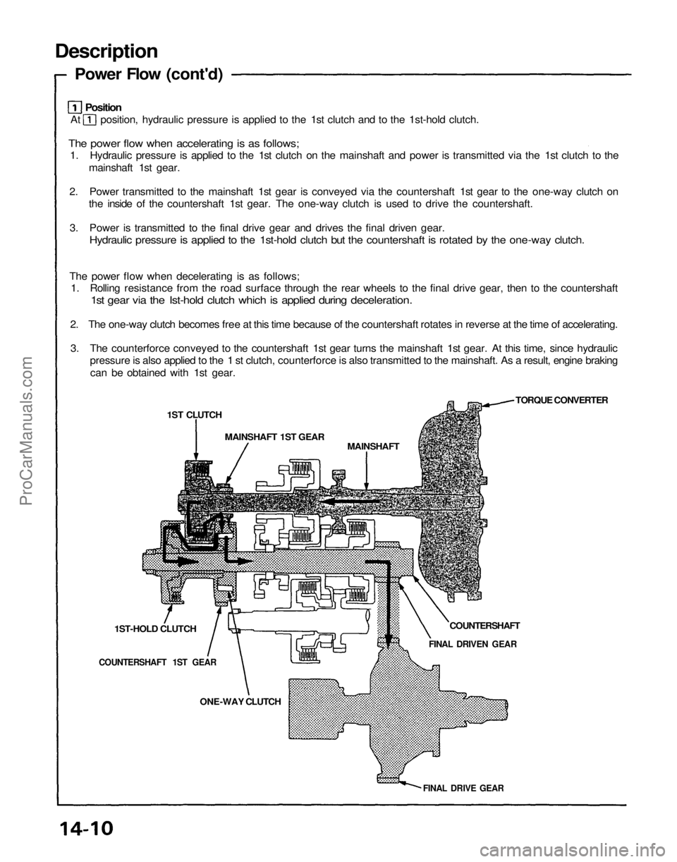
Description
Power Flow (cont'd)
Position
At position, hydraulic pressure is applied to the 1st clutch and to the 1st-hold clutch.
The power flow when accelerating is as follows;
1. Hydraulic pressure is applied to the 1st clutch on the mainshaft and power is transmitted via the 1st clutch to the
mainshaft 1st gear.
2. Power transmitted to the mainshaft 1st gear is conveyed via the countershaft 1st gear to the one-way clutch on
the inside of the countershaft 1st gear. The one-way clutch is used to drive the countershaft.
3. Power is transmitted to the final drive gear and drives the final driven gear.
Hydraulic pressure is applied to the 1st-hold clutch but the countershaft is rotated by the one-way clutch.
The power flow when decelerating is as follows;
1. Rolling resistance from the road surface through the rear wheels to the final drive gear, then to the countershaft
1st gear via the Ist-hold clutch which is applied during deceleration.
2. The one-way clutch becomes free at this time because of the countershaft rotates in reverse at the time of accelerating.
3. The counterforce conveyed to the countershaft 1st gear turns the mainshaft 1st gear. At this time, since hydraulic
pressure is also applied to the 1 st clutch, counterforce is also transmitted to the mainshaft. As a result, engine braking
can be obtained with 1st gear.
1ST CLUTCH
MAINSHAFT 1ST GEAR
MAINSHAFT
TORQUE CONVERTER
COUNTERSHAFT
FINAL DRIVEN GEAR
1ST-HOLD CLUTCH
COUNTERSHAFT 1ST GEAR
ONE-WAY CLUTCH
FINAL DRIVE GEARProCarManuals.com
Page 1225 of 1640
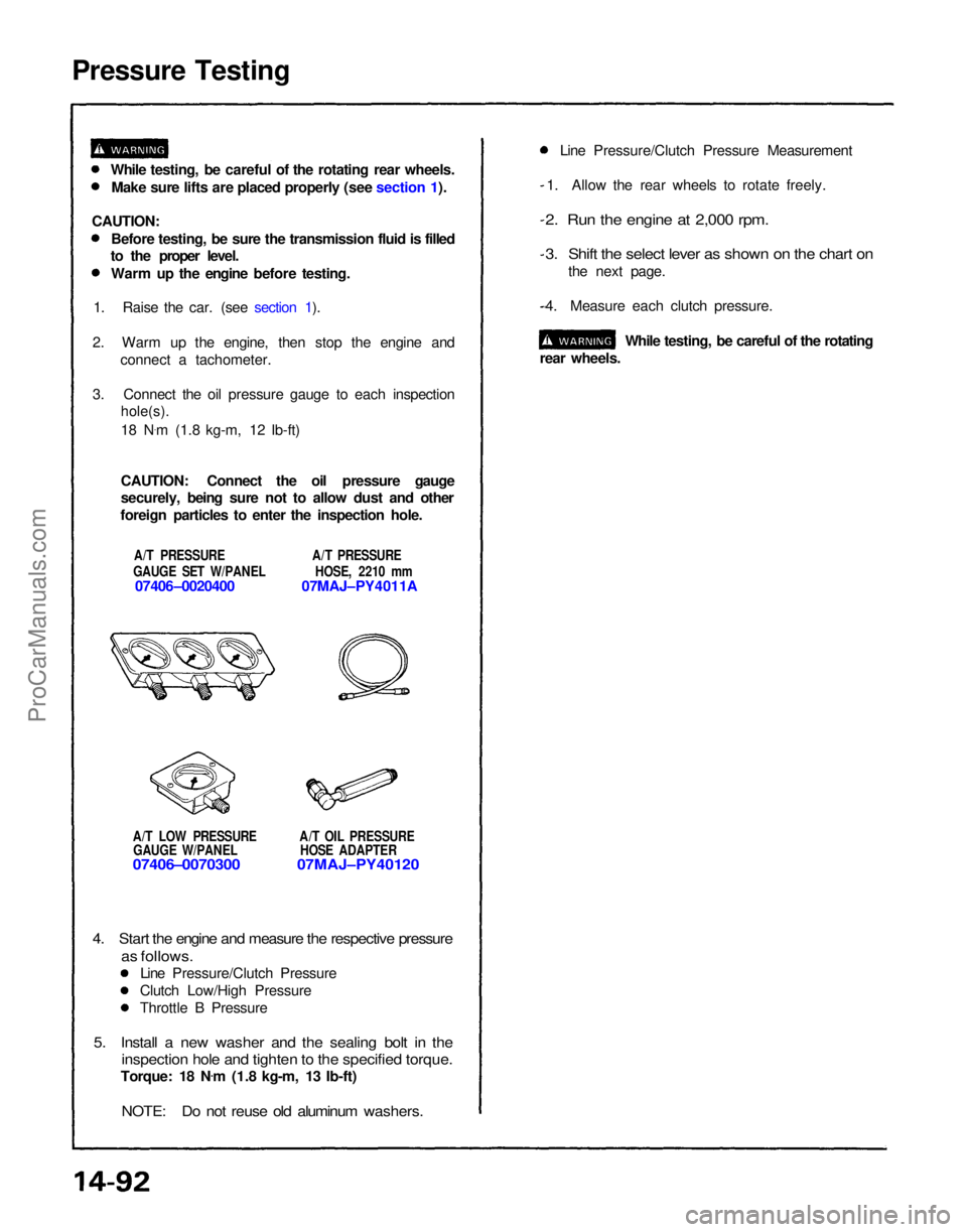
Pressure Testing
A/T LOW PRESSURE A/T OIL PRESSUREGAUGE W/PANEL HOSE ADAPTER
07406–0070300 07MAJ–PY40120
1. Allow the rear wheels to rotate freely.
2. Run the engine at 2,000 rpm.
3. Shift the select lever as shown on the chart on
the next page.
4. Measure each clutch pressure.
While testing, be careful of the rotating
rear wheels.
4. Start the engine and measure the respective pressure
as follows.
Line Pressure/Clutch Pressure
Clutch Low/High Pressure
Throttle B Pressure
5. Install a new washer and the sealing bolt in the
inspection hole and tighten to the specified torque.
Torque: 18 N .
m (1.8 kg-m, 13 Ib-ft)
NOTE: Do not reuse old aluminum washers.
While testing, be careful of the rotating rear wheels.
Make sure lifts are placed properly (see section 1).
CAUTION: Before testing, be sure the transmission fluid is filled
to the proper level.
Warm up the engine before testing.
1. Raise the car. (see section 1).
2. Warm up the engine, then stop the engine and connect a tachometer.
3. Connect the oil pressure gauge to each inspection
hole(s).
18 N .
m (1.8 kg-m, 12 Ib-ft)
CAUTION: Connect the oil pressure gauge
securely, being sure not to allow dust and other
foreign particles to enter the inspection hole.
A/T PRESSURE A/T PRESSURE
GAUGE SET W/PANEL HOSE, 2210 mm
07406–0020400 07MAJ–PY4011A Line Pressure/Clutch Pressure MeasurementProCarManuals.com
Page 1313 of 1640
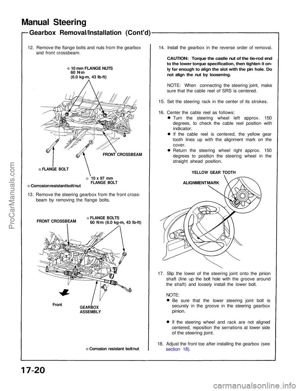
Manual Steering
Gearbox Removal/Installation (Cont'd)
12. Remove the flange bolts and nuts from the gearbox and front crossbeam.
10 mm FLANGE NUTS
60 N ·
m
(6.0 kg-m, 43 Ib-ft)
FRONT CROSSBEAM
10 x 97 mm
FLANGE BOLT
FLANGE BOLT
Corrosion resistant bolt/nut
13. Remove the steering gearbox from the front cross- beam by removing the flange bolts.
FLANGE BOLTS
60 N.
m (6.0 kg-m, 43 Ib-ft)
FRONT CROSSBEAM
Front
GEARBOX
ASSEMBLY
Corrosion resistant bolt/nut
14. Install the gearbox in the reverse order of removal.
CAUTION: Torque the castle nut of the tie-rod end
to the lower torque specification, then tighten it on-
ly far enough to align the slot with the pin hole. Do
not align the nut by loosening.
NOTE: When connecting the steering joint, make
sure that the cable reel of SRS is centered.
15. Set the steering rack in the center of its strokes.
16. Center the cable reel as follows: Turn the steering wheel left approx. 150
degrees, to check the cable reel position with
indicator.
If the cable reel is centered, the yellow gear
tooth lines up with the alignment mark on the
cover.
Return the steering wheel right approx. 150
degrees to position the steering wheel in the
straight ahead position.
YELLOW GEAR TOOTH
ALIGNMENT MARK
17. Slip the lower of the steering joint onto the pinion shaft (line up the bolt hole with the groove around
the shaft) and loosely install the lower bolt.
NOTE:
Be sure that the lower steering joint bolt is
securely in the groove in the steering gearbox
pinion.
If the steering wheel and rack are not aligned
centered, reposition the serrations at lower side
of the steering joint.
18. Adjust the front toe after installing the gearbox (see section 18).ProCarManuals.com
Page 1325 of 1640
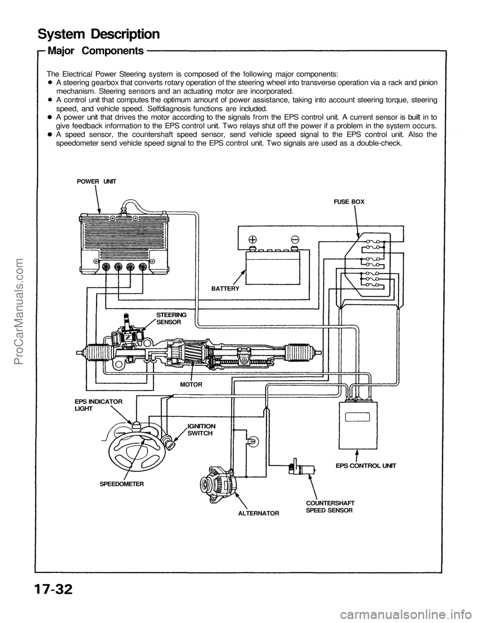
FUSE BOX
System Description
Major Components
The Electrical Power Steering system is composed of the following major components:
EPS CONTROL UNIT
COUNTERSHAFT
SPEED SENSOR
ALTERNATOR
SPEEDOMETER
EPS INDICATOR
LIGHT
STEERING
SENSOR
BATTERY
POWER UNIT
MOTOR
IGNITION
SWITCH
A steering gearbox that converts rotary operation of the steering wheel into transverse operation via a rack and pinion
mechanism. Steering sensors and an actuating motor are incorporated.
A control unit that computes the optimum amount of power assistance, taking into account steering torque, steering
speed, and vehicle speed. Selfdiagnosis functions are included.
A power unit that drives the motor according to the signals from the EPS control unit. A current sensor is built in to
give feedback information to the EPS control unit. Two relays shut off the power if a problem in the system occurs.
A speed sensor, the countershaft speed sensor, send vehicle speed signal to the EPS control unit. Also the
speedometer send vehicle speed signal to the EPS control unit. Two signals are used as a double-check.ProCarManuals.com