Page 265 of 1640

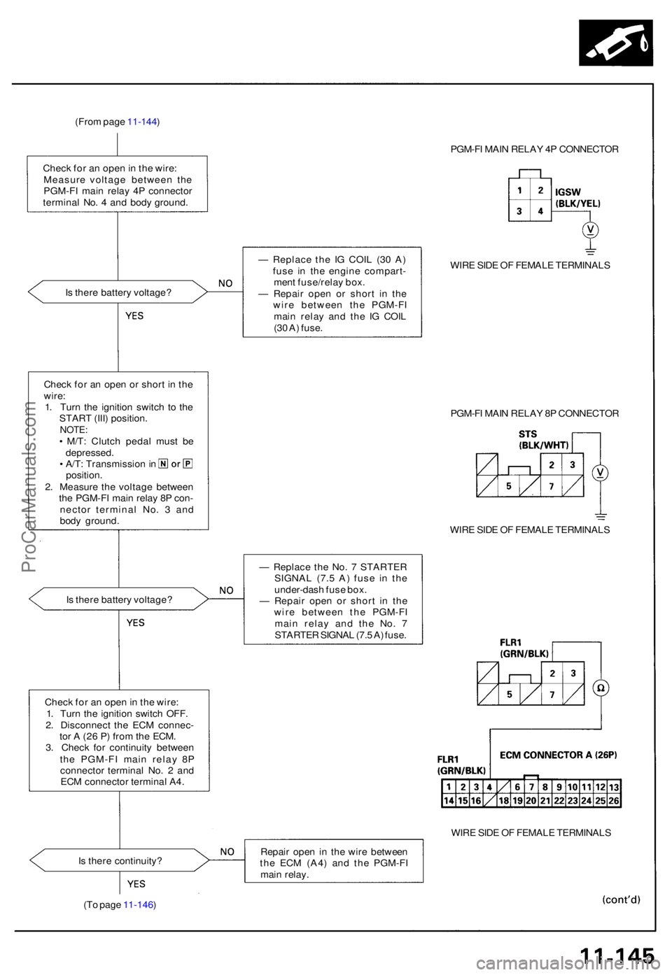
(From pag e 11-144 )
Chec k fo r a n ope n in th e wire :
Measur e voltag e betwee n th e
PGM-F I mai n rela y 4 P connecto r
termina l No . 4 an d bod y ground . PGM-F
I MAI N RELA Y 4 P CONNECTO R
I s ther e batter y voltage ? —
Replac e th e I G COI L (3 0 A )
fus e i n th e engin e compart -
men t fuse/rela y box .
— Repai r ope n o r shor t i n th e
wir e betwee n th e PGM-F I
mai n rela y an d th e I G COI L
(3 0 A ) fuse . WIR
E SID E O F FEMAL E TERMINAL S
Chec k fo r a n ope n o r shor t i n th e
wire :
1 . Tur n th e ignitio n switc h t o th e
STAR T (III ) position .
NOTE:• M/T : Clutc h peda l mus t b e
depressed .
• A/T : Transmissio n in
position .
2 . Measur e th e voltag e betwee n
th e PGM-F I mai n rela y 8 P con -
necto r termina l No . 3 an d
bod y ground . PGM-F
I MAI N RELA Y 8 P CONNECTO R
WIR E SID E O F FEMAL E TERMINAL S
I s ther e batter y voltage ? —
Replac e th e No . 7 STARTE R
SIGNA L (7. 5 A ) fus e i n th e
under-das h fus e box .
— Repai r ope n o r shor t i n th e
wir e betwee n th e PGM-F I
mai n rela y an d th e No . 7
STARTE R SIGNA L (7. 5 A ) fuse .
Chec k fo r a n ope n in th e wire :
1 . Tur n th e ignitio n switc h OFF .
2 . Disconnec t th e EC M connec -
to r A (2 6 P ) fro m th e ECM .
3 . Chec k fo r continuit y betwee n
th e PGM-F I mai n rela y 8 P
connecto r termina l No . 2 an d
EC M connecto r termina l A4 .
WIRE SID E O F FEMAL E TERMINAL S
I s ther e continuity ? Repai
r ope n i n th e wir e betwee n
th e EC M (A4 ) an d th e PGM-F I
mai n relay .
(T o pag e 11-146 )
ProCarManuals.com
Page 268 of 1640
Intake Air System
System Description
The system supplies air for all engine needs. It consists of the intake air pipe, Air Cleaner (ACL), intake air duct, throttle
body, and intake manifold. A resonator in the intake air duct provides additional silencing as air is drawn into the system.
IAB CONTROL
SOLENOID VALVE
To No. 5 BACK-UP LIGHTS
ALTERNATOR TURN SIGNALS
(15 A) FUSE
IAB
CONTROL
DIAPHRAGM
IAB
CONTROL
VALVE
THROTTLE
VALVE
INTAKE
AIR DUCT
ACL
RESONATOR
VARIOUS
SENSORS
INTAKE
MANIFOLDProCarManuals.com
Page 274 of 1640
Intake Air System
Intake Air Bypass (IAB) Control System
Description
Satisfactory power performance is achieved by closing and opening the intake air bypass (IAB) control valves. High torque
at low engine speed is achieved when the valves are closed, whereas high power at high engine speed is achieved when
the valves are opened.
INTAKE AIR BYPASS (IAB) CONTROL
SOLENOID VALVE ON
ENGINE SPEED IS ABOVE 4,800 rpm
OPEN: HIGH ENGINE SPEED
IAB CONTROL
SOLENOID
VALVE
To No. 5 BACK-UP LIGHTS
ALTERNATOR TURN SIGNALS
(15 A) FUSE
IAB
CONTROL
DIAPHRAGM
IAB
CONTROL
VALVE
CLOSED: LOW ENGINE SPEEDProCarManuals.com
Page 280 of 1640

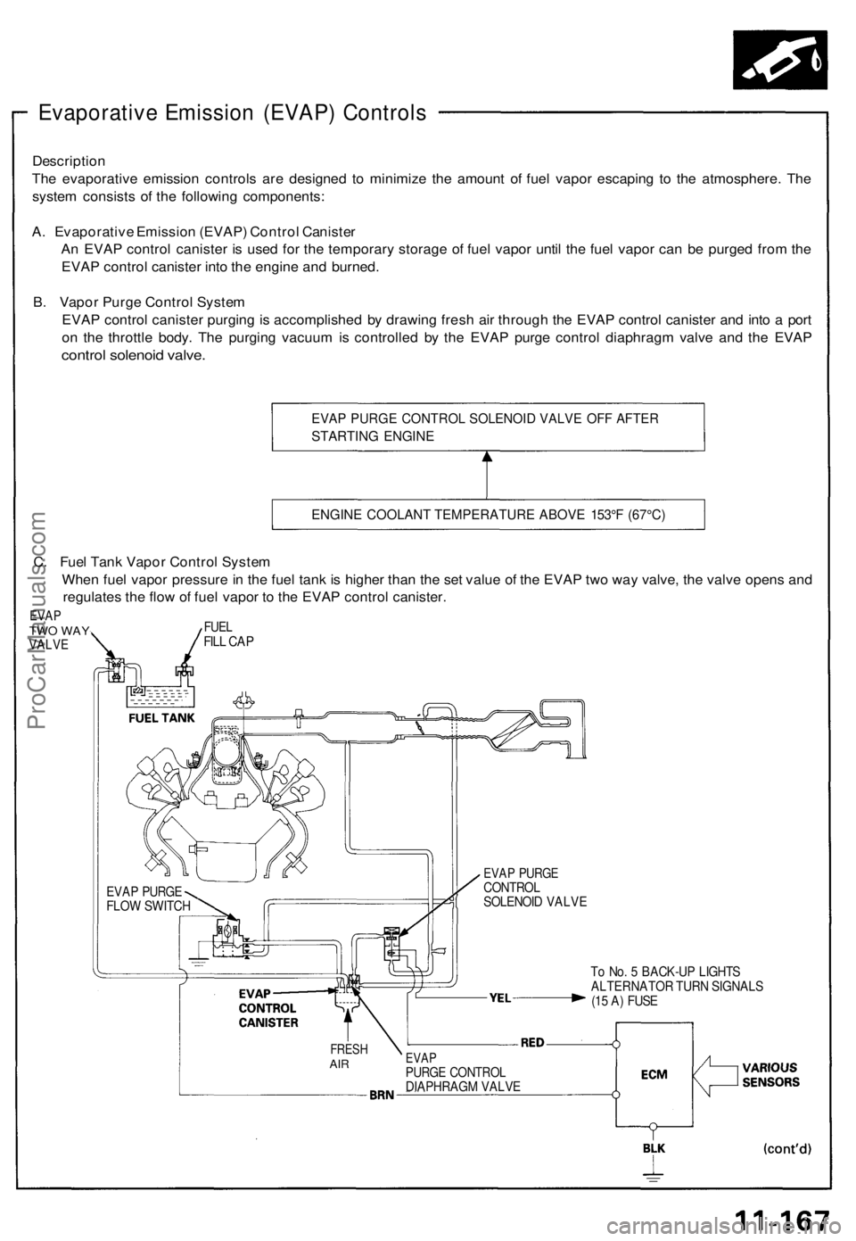
Evaporative Emission (EVAP) Controls
Description
The evaporative emission controls are designed to minimize the amount of fuel vapor escaping to the atmosphere. The
system consists of the following components:
A. Evaporative Emission (EVAP) Control Canister
An EVAP control canister is used for the temporary storage of fuel vapor until the fuel vapor can be purged from the
EVAP control canister into the engine and burned.
B. Vapor Purge Control System
EVAP control canister purging is accomplished by drawing fresh air through the EVAP control canister and into a port
on the throttle body. The purging vacuum is controlled by the EVAP purge control diaphragm valve and the EVAP
control solenoid valve.
EVAP PURGE CONTROL SOLENOID VALVE OFF AFTER
STARTING ENGINE
ENGINE COOLANT TEMPERATURE ABOVE 153°F (67°C)
To No. 5 BACK-UP LIGHTS
ALTERNATOR TURN SIGNALS
(15 A) FUSE
FRESH
AIR
EVAP
PURGE CONTROL
DIAPHRAGM VALVE
EVAP PURGE
CONTROL
SOLENOID VALVE
EVAP PURGE
FLOW SWITCH
C. Fuel Tank Vapor Control System
When fuel vapor pressure in the fuel tank is higher than the set value of the EVAP two way valve, the valve opens and
regulates the flow of fuel vapor to the EVAP control canister.
EVAP
TWO WAY
VALVE
FUEL
FILL CAPProCarManuals.com
Page 416 of 1640
Component Location s
GAUGE ASSEMBL Y
UNDER-HOO D FUSE /
RELAY BO X
TRANSMISSIO N CONTRO L
MODUL E (TCM )
22 P CONNECTO R
VEHICL E SPEE D SENSO R
(VSS)
(M/T)PULS E UNI T 7 P CONNECTO R
TORQU E SENSO R 6 P CONNECTOR /
ROTATIO N SENSO R
4 P CONNECTO R
STEERING GEARBO X
(TORQU E SENSOR /
ROTATIO N SENSOR )
UNDER-DASH FUS E BO X
EP
S CONTRO L UNI T
ALTERNATO R4P CONNECTO R
ProCarManuals.com
Page 417 of 1640
GAUGE ASSEMBLY
EPS INDICATOR LIGHT
UNDER-HOOD FUSE/RELAY BOX
No. 2 (15 A)
IG SW (50 A)
CLOCK (7.5 A)
E-PS
(50 A)
UNDER-DASH FUSE BOX
No. 5 (15 A)ProCarManuals.com
Page 420 of 1640

Troubleshooting Precautions
EPS Indicator Light
Under normal conditions, the EPS indicator light in the gauge assembly comes on when the ignition switch is turned to
the ON (II) position, then goes off after the engine is started. This indicates that the bulb and its circuits are operating cor-
rectly. If there is any trouble in the system, the EPS indicator light turns on during driving, and the power steering assist is
turned off. When the EPS indicator light comes on, the control unit memorizes the DTC. In this case, the control unit does
not activate the EPS system after the engine starts again but it keeps the EPS indicator light on.
Diagnostic Trouble Code (DTC)
• The lowest DTC is indicated first.
• The DTCs continue blinking until the ignition switch is turned off.
• The DTCs are erased from the control unit when the EPS control unit VBU power supply or connector is disconnected.
• The EPS system can be reset and the control unit's memory can be erased by disconnecting the CLOCK (7.5 A) fuse for
more than ten seconds.
Self-diagnosis:
The CPU (central processing unit) controls the following when it detects a problem during self-diagnosis:
1. Turns the EPS indicator light ON to alert the driver.
2. Power assist stops, and normal manual steering operation resumes (except DTC 21 and DTC 33).
3. The EPS control unit memorizes the diagnostic trouble code (DTC).
4. After the DTC is stored in the control unit, the CPU stops self-diagnosis.
Troubleshooting:
• Before starting the troubleshooting, clear the DTC by disconnecting the CLOCK (7.5 A) fuse for ten seconds or more,
and test-drive the car. Check that the symptom of the trouble appears again, and then troubleshoot. If the problem is an
intermittent problem, the system does not become active after the engine starts even though the problem is solved.
• When both EPS indicator light and A/T "D" indicator light come on, perform the A/T troubleshooting first.
• When the customer's reported problem cannot be verified in the car, ask the customer about the conditions when the
EPS indicator light came ON, then test-drive the car under those conditions, if possible. If the EPS indicator light does
not come ON during the test, check for loose connections or poor contacts at the connectors by wiggling the harness,
etc.
• The connector terminal numbers are viewed from the wire side for the female terminals and from the terminal side for
the male terminals.
• After the repair, test-drive the car and check that the EPS indicator light does not come ON again during the test. (Refer
to the Symptom-to-System Chart for diagnostic period.)ProCarManuals.com
Page 422 of 1640
Diagnostic Trouble Code (DTC) Indication
Example:
1.3 seconds
DTC Indication Pattern:
DTC:
11
DTC:
12
EPS Indicator light ON
EPS Indicator light OFF
0.28 seconds
Repeat
Connect the SCS Turn the ignition
service connector switch ON (II)
0.36 seconds 1.3 seconds
• The DTC is indicated by a series of long and short blinks. One long blink equals 10 short blinks.
Add the long and short blinks together to determine the DTC.
• The DTCs are repeated sequentially beginning with the lowest number.
4. Remove the SCS service connector.
NOTE: The Malfunction Indicator Lamp (MIL) will stay on after the engine is started if the SCS service connector is
connected.
5. Remove the CLOCK (7.5 A) fuse in the under-hood fuse/relay box for more than 10 seconds to erase the EPS control
unit memory.ProCarManuals.com