1990 MITSUBISHI SPYDER oil
[x] Cancel search: oilPage 2078 of 2103
55-38HEATER, AIR
AND VENTILATION Compressor and Tension Pulley Engine (Non-turbo)>
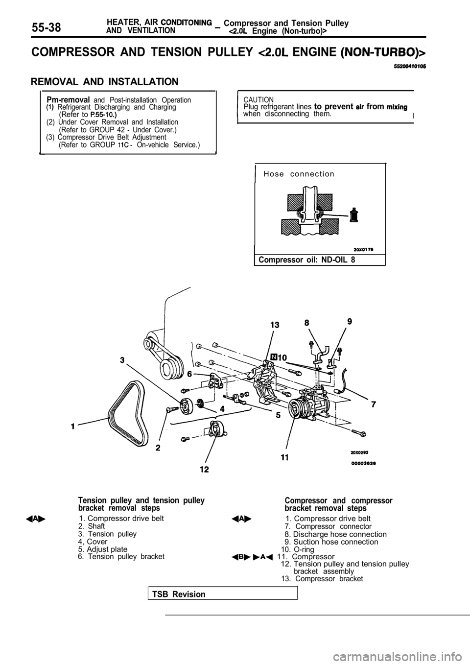
COMPRESSOR AND TENSION PULLEY ENGINE
REMOVAL AND INSTALLATION
Pm-removaland Post-installation Operation Refrigerant Discharging and Charging(Refer to (2) Under Cover Removal and Installation(Refer to GROUP 42 Under Cover.)
(3) Compressor Drive Belt Adjustment
(Refer to GROUP
On-vehicle Service.)
CAUTIONPlug refrigerant lines to prevent from when disconnecting them.I
H o s e c o n n e c t i o n
Compressor oil: ND-OIL 8
Tension pulley and tension pulley
bracket removal steps
1. Compressor drive belt2. Shaft
3. Tension pulley
4, Cover
5. Adjust plate
6. Tension pulley bracket
Compressor and compressorbracket removal steps
1. Compressor drive belt7. Compressor connector
8. Discharge hose connection
9. Suction hose connection
10. O-ring 11. Compressor 12. Tension pulley and tension pulley
bracket assembly
13. Compressor bracket
TSB Revision
Page 2079 of 2103
Compressor
AND VENTILATION,
REMOVAL SERVICE
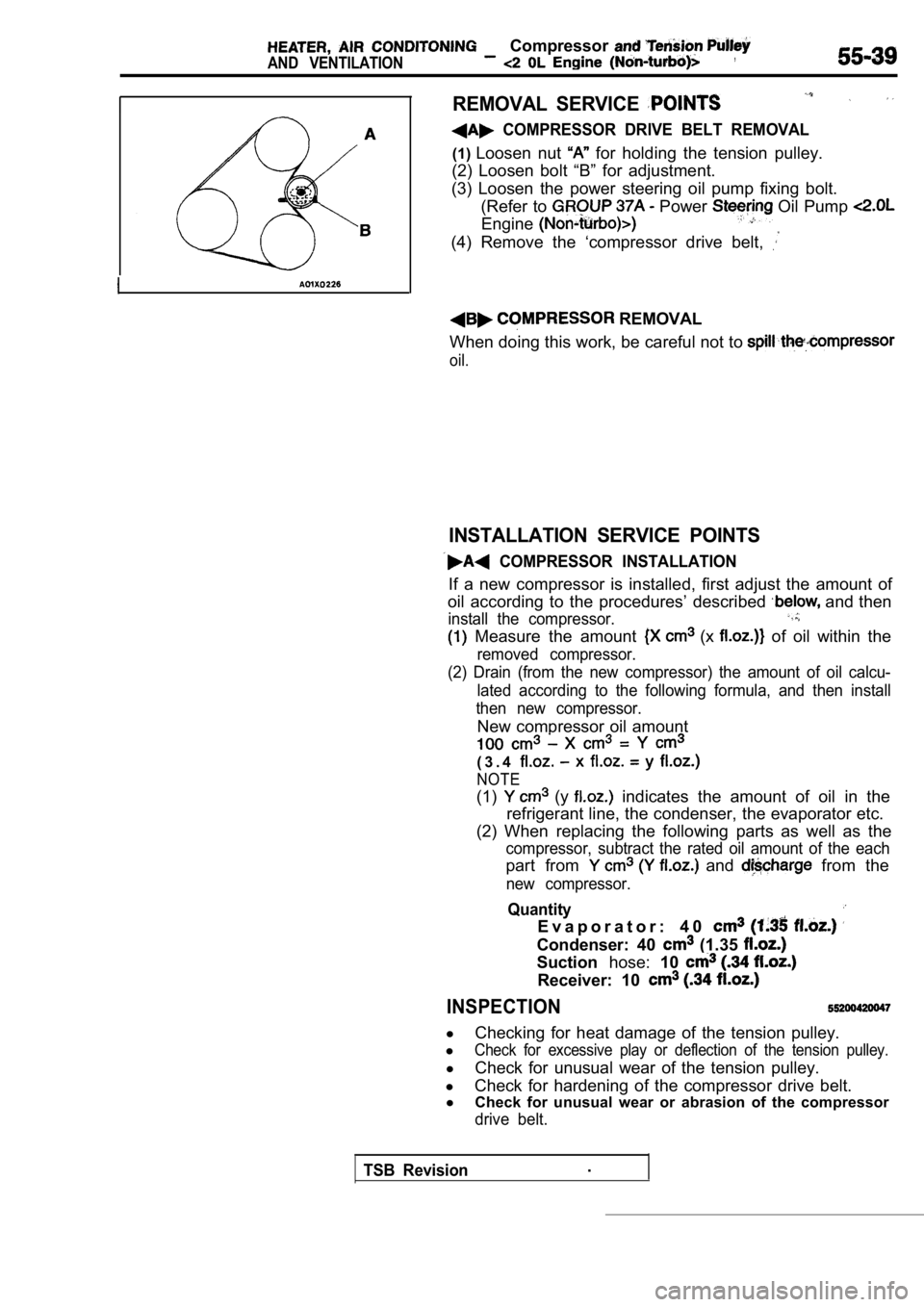
COMPRESSOR DRIVE BELT REMOVAL
(1)Loosen nut for holding the tension pulley.
(2) Loosen bolt “B” for adjustment.
(3) Loosen the power steering oil pump fixing bolt. (Refer to
Power Oil Pump
Engine
(4) Remove the ‘compressor drive belt,
REMOVAL
When doing this work, be careful not to
oil.
INSTALLATION SERVICE POINTS
COMPRESSOR INSTALLATION
If a new compressor is installed, first adjust the amount of
oil according to the procedures’ described
and then
install the compressor.
Measure the amount (x of oil within the
removed compressor.
(2) Drain (from the new compressor) the amount of o il calcu-
lated according to the following formula, and then install
then new compressor.
New compressor oil amount
( 3 . 4
NOTE
(1) (y indicates the amount of oil in the
refrigerant line, the condenser, the evaporator etc .
(2) When replacing the following parts as well as t he
compressor, subtract the rated oil amount of the each
part from and from the
new compressor.
Quantity
E v a p o r a t o r : 4 0
Condenser: 40 (1.35
Suctionhose:10
Receiver: 10
INSPECTION
l
Checking for heat damage of the tension pulley.
l
Check for excessive play or deflection of the tensi on pulley.
l
Check for unusual wear of the tension pulley.
l Check for hardening of the compressor drive belt.
l Check for unusual wear or abrasion of the compresso r
drive belt.
TSB Revision.
Page 2080 of 2103
00003640
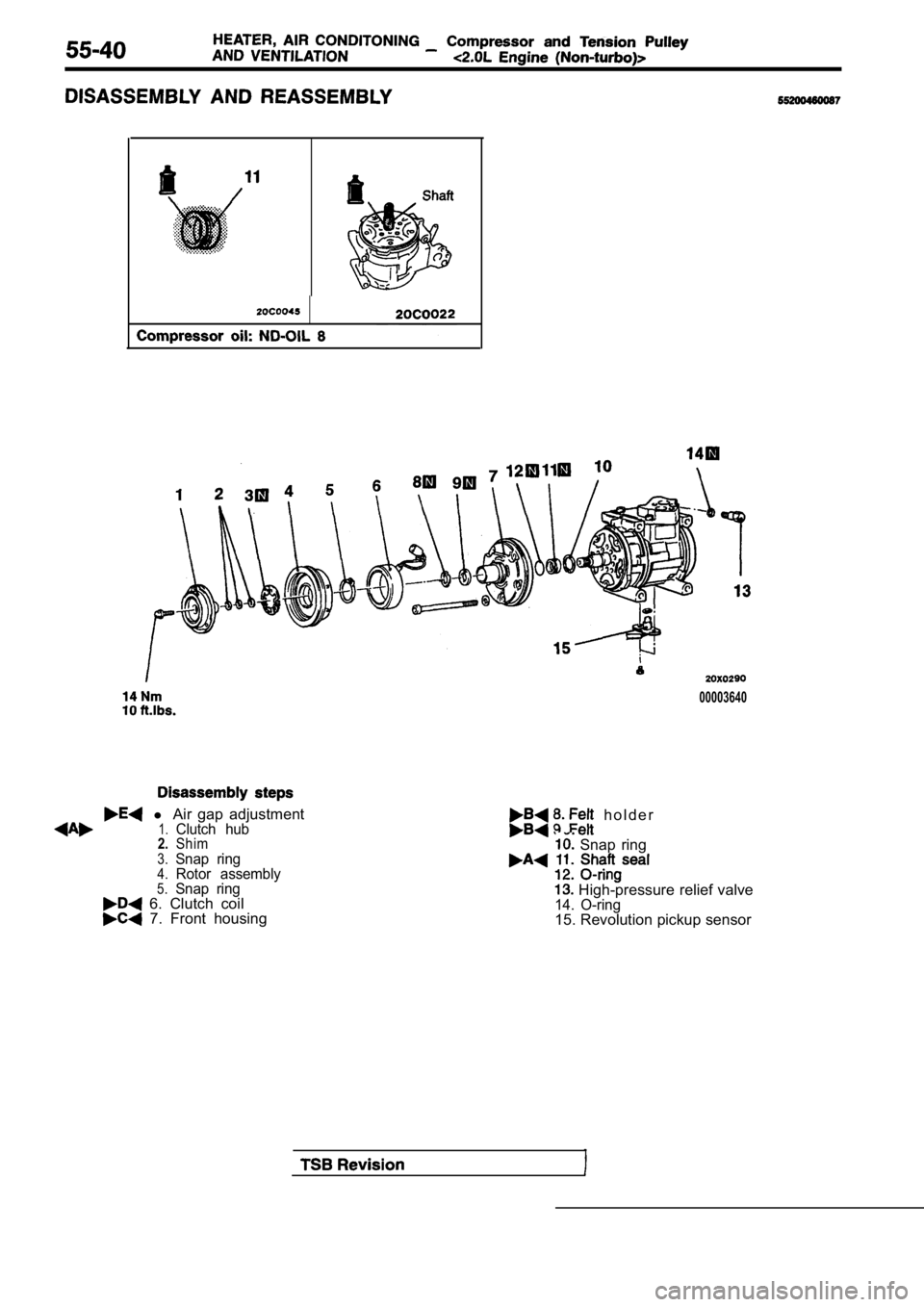
l Air gap adjustment1.Clutch hub2.Shim3.Snap ring4.Rotor assembly5.Snap ring 6. Clutch coil 7. Front housing
h o l d e r
Snap ring
High-pressure relief valve14. O-ring15. Revolution pickup sensor
Page 2081 of 2103
![MITSUBISHI SPYDER 1990 Service Repair Manual and Tension
Engine (Non-turbo)>
Bolt mm in.)]
Socket
Deep socket
(14 mm
in.)]
TSB
HUB REMOVAL
(1) Remove the clutch hub mounting bolt.
(2) Tighten a
mm in.) bolt into the ho MITSUBISHI SPYDER 1990 Service Repair Manual and Tension
Engine (Non-turbo)>
Bolt mm in.)]
Socket
Deep socket
(14 mm
in.)]
TSB
HUB REMOVAL
(1) Remove the clutch hub mounting bolt.
(2) Tighten a
mm in.) bolt into the ho](/manual-img/19/57345/w960_57345-2080.png)
and Tension
Engine (Non-turbo)>
Bolt mm in.)]
Socket
Deep socket
(14 mm
in.)]
TSB
HUB REMOVAL
(1) Remove the clutch hub mounting bolt.
(2) Tighten a
mm in.) bolt into the hole of the
clutch hub to remove the serration assembly the shaft
and the clutch hub.
SEAL INSTALLATION
Use a 21 mm in.) socket to install the shaft seal so
that the O-ring assembly side is facing the front h ousing.
FELT, FELT HOLDER INSTALLATION
After installing the felt in the felt holder, them to the
front housing using a 14 mm
deep socket.
FRONT HOUSING INSTALLATION
(1) Apply compressor oil to the shaft.
Compressor oil: ND-OIL 8
(2) Install the front housing without damaging the shaft seal
lip.
(3) After installing the front housing, install the clutch hub
mounting bolt to the shaft, and check that the breakaway
torque is within the torque value.
Breakaway torque:
Nm (4 or less
Page 2082 of 2103
55-42
Pin
Main unit of conditioningcompressor
Compressor side
connector
2
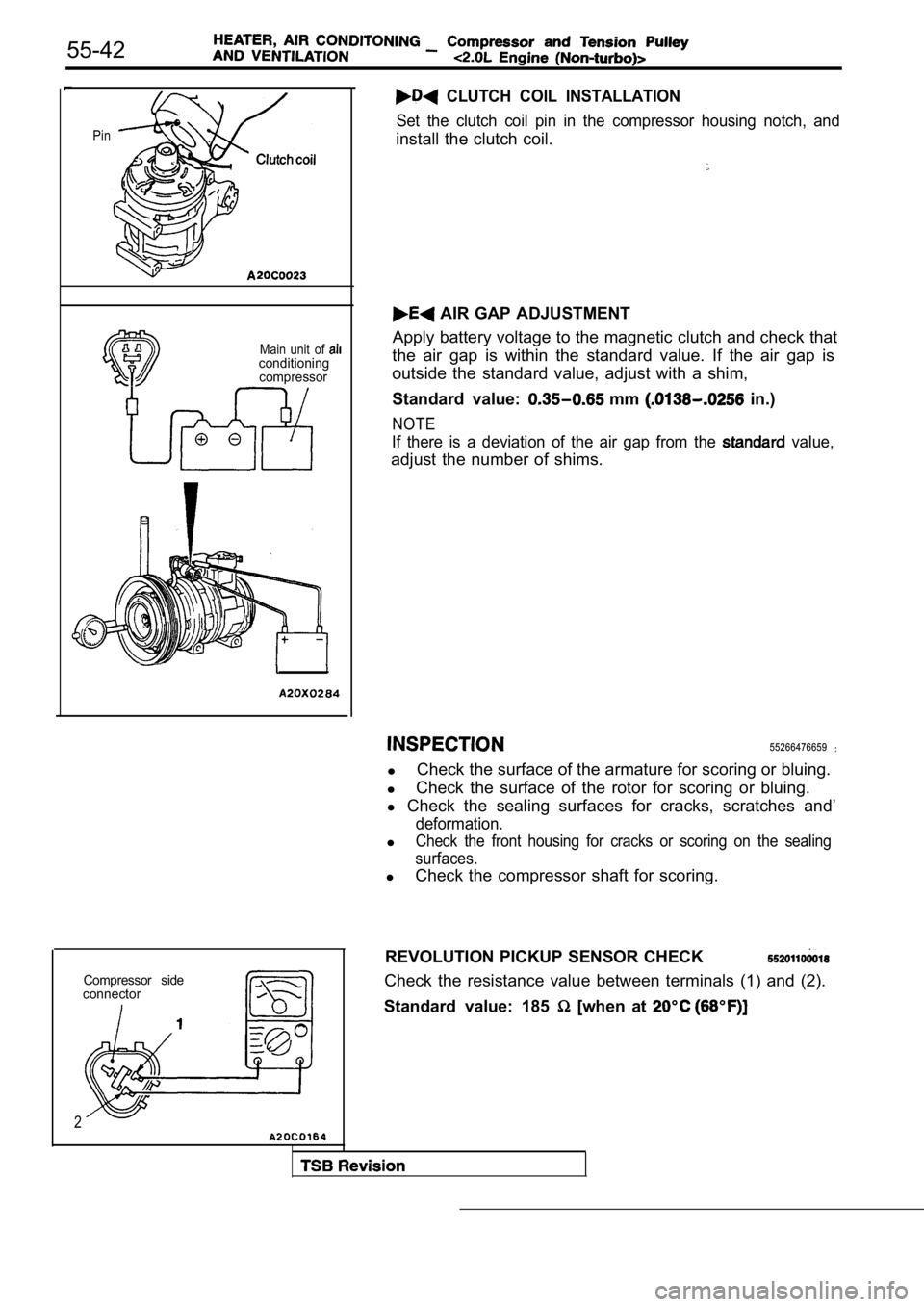
CLUTCH COIL INSTALLATION
Set the clutch coil pin in the compressor housing n otch, and
install the clutch coil.
AIR GAP ADJUSTMENT
Apply battery voltage to the magnetic clutch and ch eck that
the air gap is within the standard value. If the ai r gap is
outside the standard value, adjust with a shim,
Standard value:
mm in.)
NOTE
If there is a deviation of the air gap from the value,
adjust the number of shims.
55266476659
l Check the surface of the armature for scoring or bl
uing.
l Check the surface of the rotor for scoring or bluin
g.
l Check the sealing surfaces for cracks, scratches an d’
deformation.
lCheck the front housing for cracks or scoring on the sealing
surfaces.
l Check the compressor shaft for scoring.
REVOLUTION PICKUP SENSOR CHECK
Check the resistance value between terminals (1) an d (2).
Standard value: 185
[when at
Page 2085 of 2103
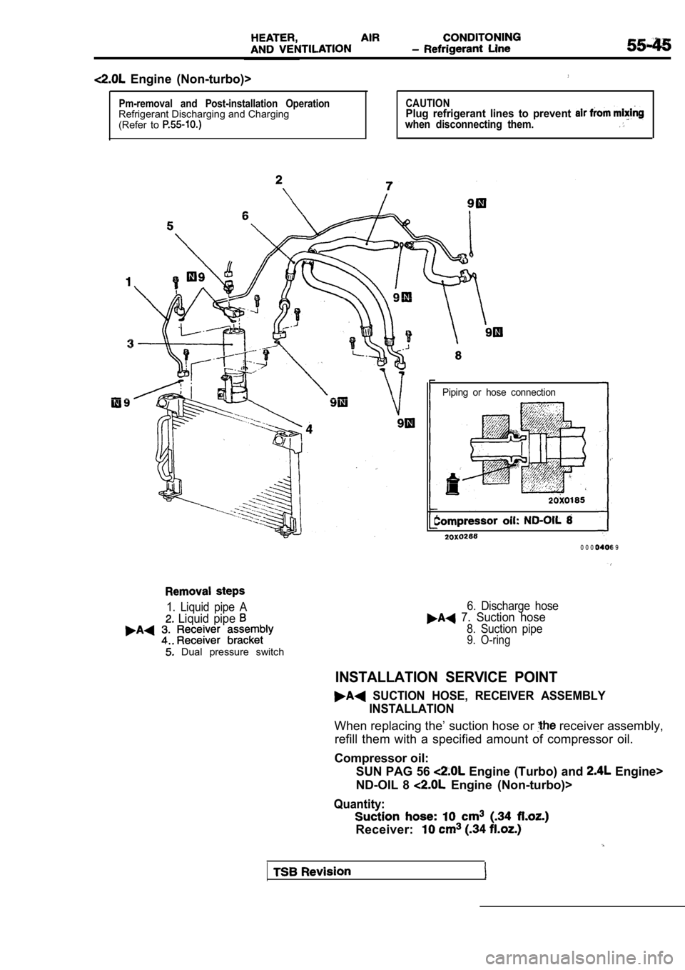
Engine (Non-turbo)>
Pm-removal and Post-installation OperationRefrigerant Discharging and Charging
(Refer to CAUTIONPlug refrigerant lines to prevent when disconnecting them.
Piping or hose connection
0 0 0 0 4 0 6 9
1. Liquid pipe A
Liquid pipe
Dual pressure switch
6. Discharge hose 7. Suction hose
8. Suction pipe9. O-ring
INSTALLATION SERVICE POINT
SUCTION HOSE, RECEIVER ASSEMBLYINSTALLATION
When replacing the’ suction hose or receiver assembly,
refill them with a specified amount of compressor o il.
Compressor oil: SUN PAG 56
Engine (Turbo) and Engine>
ND-OIL 8
Engine (Non-turbo)>
Quantity:
Receiver:
Page 2088 of 2103
HEATER, AIR Condenser and
Condenser Fan’ Motor
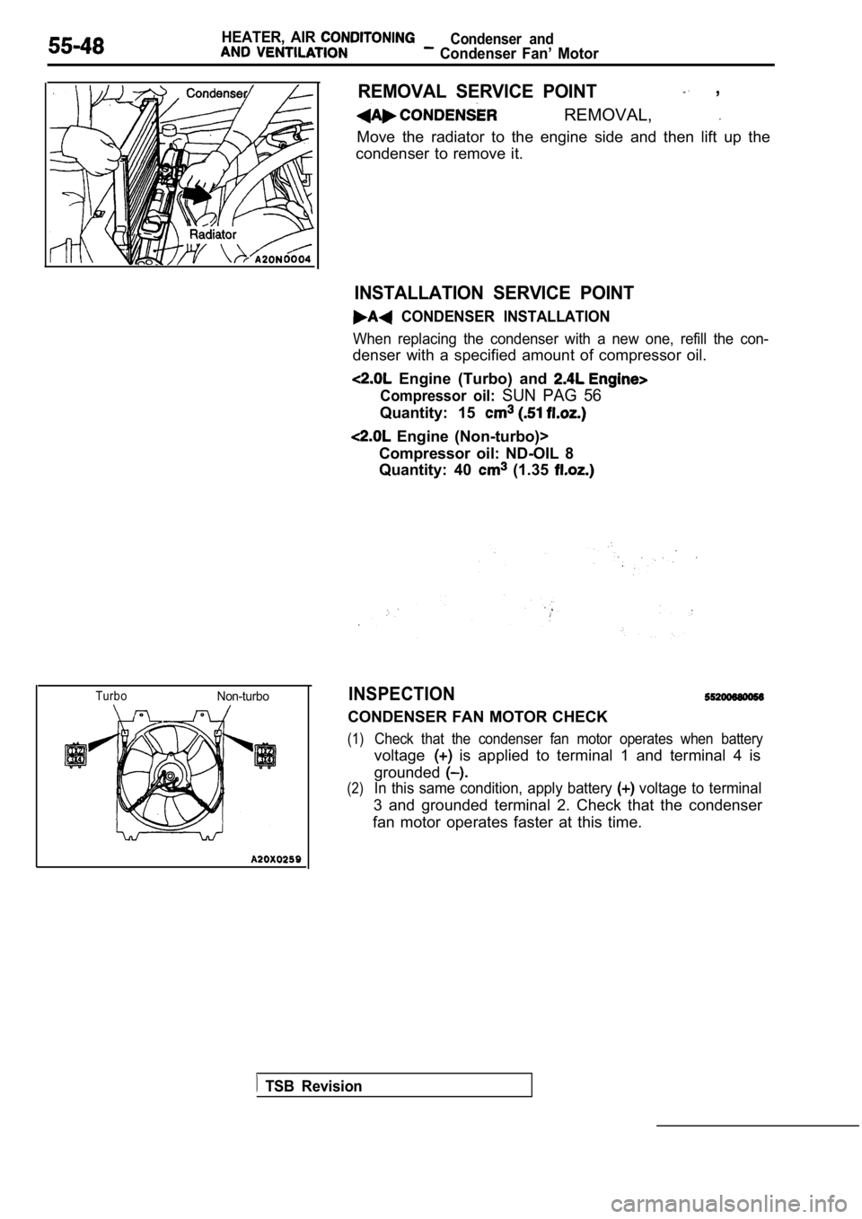
TurboNon-turbo
REMOVAL SERVICE POINT ,
REMOVAL,
Move the radiator to the engine side and then lift up the
condenser to remove it.
INSTALLATION SERVICE POINT
CONDENSER INSTALLATION
When replacing the condenser with a new one, refill the con-
denser with a specified amount of compressor oil.
Engine (Turbo) and
Compressor oil: SUN PAG 56
Quantity: 15
Engine (Non-turbo)>
Compressor oil: ND-OIL 8
Quantity: 40
(1.35
INSPECTION
CONDENSER FAN MOTOR CHECK
(1)Check that the condenser fan motor operates when ba ttery
voltage is applied to terminal 1 and terminal 4 is
grounded
(2)In this same condition, apply battery voltage to terminal
3 and grounded terminal 2. Check that the condenser
fan motor operates faster at this time.
TSB Revision
Page 2093 of 2103

ALPHABETICAL
A
ABS OPERATIONCheck. . . . . . . . . . . . . . . . . . . . . . . . . . . . . . . . . . .
. . . . . . . . . . . . . . . . . . . . . . . . . . . . . . . . . . .
ABS-ECU. . . . . . . . . . . . . . . . . . . . . . . . . . . . . . . . . . . . . . . . .
. . . . . . . . . . . . . . . . . . . . . . . . . . . . . . . . . . . . . . . . .
ACCELERATOR CABLE. . . . . . . . . . . . . . . . . . . . . . . . . . . . . . . .Adjustment. . . . . . . . . . . . . . . . . . . . . . . . . . . . . . . . . . . . . . . . .
Check. . . . . . . . . . . . . . . . . . . . . . . . . . . . . . . . . . . . . . . . . . . . .ACCELERATOR PEDAL. . . . . . . . . . . . . . . . . . . . . . . . . . . . . . . .
ADAPTER, Transfer Case . . . . . . . . . . . . . . . . . .
AERO PARTS. . . . . . . . . . . . . . . . . . . . . . . . . . . . . . . . . . . . . . . .
AIR BAG CONTROL UNIT (SRS-ECU), SRS. . . . . . . . . . .AIR BAG MODULES. . . . . . . . . . . . . . . . . . . . . . . . . . . . . . . . .
Deployed Disposal Procedures. . . . . . . . . . . . . . . . . . . . .
Disposal Procedures. . . . . . . . . . . . . . . . . . . . . . . . . . . . .
Disposal. . . . . . . . . . . . . . . . . . . . . . . . . . . . .
AIR CLEANER ELEMENT, Maintenance. . . . . . . . . . . . . . . . . .AIR CONDITIONING SWITCH
ENGINE (NON-TURBO)>. . . . . . . . . . . . . . ENGINE (TURBO) AND .AIR COOLER, charge. . . . . . . . . . . . . . . . . . . . . . . . . . . . . . . . . . .
AIR FILTER. . . . . . . . . . . . . . . . . . . . . . . . . . . . . . . . . . . . . . . . . .
ALIGNMENT
Front Wheel, Check and Adjustment. . . . . . . . . . . . . . . . .
Wheel, Rear, Check and Adjustment. . . . . . . . . . . . . . . . . . .AMPLIFIER. . . . . . . . . . . . . . . . . . . . . . . . . . . . . . . . . . . . . . . . . .
GEAR AND TRANSFER DRIVE GEAR SET
. . . . . . . . . . . . . . . . . . . . . . . . . . . . . . . .
. . . . . . . . . . . . . . . . . . . . . . . . . . . . . . . . . . . . . . . .
ANTENNA.
ARM Compression, Lower
. . . . . . . . . . . . . . . . . . . . . . . . . . . . . . .Lateral, Lower. . . . . . . . . . . . . . . . . . . . . . . . . . . . . . . . . . .
Lower. . . . . . . . . . . . . . . . . . . . . . . . . . . . . . . . . . . . . . . . . . . . .
Toe Control. . . . . . . . . . . . . . . . . . . . . . . . . . . . . . . . . . . . . . . .
Trailing. . . . . . . . . . . . . . . . . . . . . . . . . . . . . . . . . . . . . . . . . . . .
Upper
Suspension>. . . . . . . . . . . . . . . . . . . . . . . . . . .ARMS, Rocker . . . . . . . . . . . . . . . . . . . . . . . . . . .11AUTO-CRUISE CONTROL. . . . . . . . . . . . . . . . . . . . . . . . . . . . .
AUTO-CRUISE CONTROL CABLE, Check andAdjustment. . . . . . . . . . . . . . . . . . . . . . . . . . . . . . . . . . . . . . . . . . .
AUTO-CRUISE CONTROL COMPONENT, Check. . . . . . . . .AUTO-CRUISE CONTROL SYSTEM, Operation Check. . . .AUTOMATIC TRANSAXLE FLUID, Maintenance. . . . . . . . . .AUTOMATIC TRANSAXLE CONTROL COMPONENTCheck
ENGINE (NON-TURBO)>.. . . . . . . . . . . .Layout ENGINE (NON-TURBO)>. . . . . . . . . . . .AUTOMATIC TRANSAXLE KEY INTERLOCK AND SHIFT LOCKMECHANISMS
ENGINE (NON-TURBO)>. . . . . . . . . . . . . . . . . . .
ENGINE (TURBO) AND ENGINE>.. . . . . . .AXLE
Rear, Total Backlash Check. . . . . . . . . . . . . . . . . . . . . . . . . .
AXLE OIL
Rear, Maintenance
. . . . . . . . . . . . . . . . . . . . . . . . . . . . . . . . .
BACK-UP LIGHT. . . . . . . . . . . . . . . . . . . . . . . . . . . . . . . . . . . . .BALL JOINT, Tie Rod End, Breakaway Torque Check. . . . .BALL JOINT SEALS, Maintenance. . . . . . . . . . . . . . . . . . . . . .
BARStabilizer Suspension>. . . . . . . . . . . . . . . . . . . . .
Suspension>. . . . . . . . . . . . . . . . . . . . . . . .
BASIC IDLE SPEED, Adjustment ENGINE (TURBO)
AND ENGINE>. . . . . . . . . . . . . . . . . . . . . . . . . . . . . . . .
BATTERY
Charging
. . . . . . . . . . . . . . . . . . . . . . . . . . . . . . . . . . . . . . . . . .
Check. . . . . . . . . . . . . . . . . . . . . . . . . . . . . . . . . . . . . . . . . . ..Testing Procedure. . . . . . . . . . . . . . . . . . . . . . . . . . . . .. . .
BELT
Compressor, Adjustment. . . . . . . . . . . . . . . . . . . . . . . . .
(For Generator), Maintenance. . . . . . . . . . . .. . . . . (For Power steering pump), Maintenance. . . . . . . . . (For Water pump), Maintenance. . . . . . . . .. .. . .Timing. . . . . . . . . . . . . . . . . . . .
. . . . . . . . . . . . . . . . . . . . . . . . . . .
Timing. . . . . . . . . . . . . . . . . . . . . . . . . . . . .
. . . . . . . . . . . . . . . . . . . . . ... . . . . . . . .
. . . .Timing, Maintenance. . . . . . . . . . . . . . . . . . . . . . . . . . . . . . . .
BLEEDING
ABS. . . . . . . . . . . . . . . . . . . . . . . . . . . . . . . . . . . . . . . . . . . .
Basic Brakes. . . . . . . . . . . . . . . . . . . . . . . . . . . . . . . . . . . .
Clutch. . . . . . . . . . . . . . . . . . . . . . . . . . . . . . . . . . .. . . . . . .. . . . . . . . . . . . . . . . . . . . . . . . . . . . . . . . . . . . . . . . . .
BLOWER. . . . . . . . . . . . . . . . . . . . . . . . . . . . . . . . . . . . . . . . . . . .
BOLTHub, Replacement . . . . . . . . . . . . . . . . . . .. . . . .
. . . . . . . . . . . . . . . . . . . . . .
. . . . . . . . . . . . . . . . . . . . . . 2 7 4 1
BOOSTER
Brake. . . . . . . . . . . . . . . . . . . . . . . . . . . . . . . . . . . .
. . . . . . . . . . . . . . . . . . . . . . . . . . . . .
Brake, Operating Test. . . . . . . . . . . . . . . . . . . . . . . . . . . . . O-IBOOTS, Shaft, Maintenance. . . . . . . . . . . . . . . . . . . . . . .
BRACKET. . . . . . . . . . . . . . . . . . . . . . . . . . . . . .
BRAKE
. . . . . . . . . . . . . . . . . . . . . . . . . . . . . . . . . . . . . .
Disc, Rear. . . . . . . . . . . . . . . . . . . . . . . . . . . . . . . . . . . . . . .
Low-reverse. . . . . . . . . .. . . . . . . .. . . . . . . . . . . . . . . . . . . . . . . . . . . .
BRAKE BOOSTER
. . . . . . . . . . . . . . . . . . . . . . . . . . . . . . . . . . . . . . . . . .
Test. . . . . . . . . . . . . . . . . . . . . . . . . . . . . . . . . . . .
BRAKE DISC
Front, Run-out Check. . . . . . . . . . . . . . . . . . . . . . . . . .. Run-out Correction. . . . . . . . . . . . . . . . . . . . . . . . . .
Front, Thickness Check. . . . . . . . . . . . . . . . . . . . . . . . . . .
Rear, Run-out Check.. . . . . . . . . . . . . . . . . . . . . . . . . . . . .
Rear, Run-out Correction. . . . . . . . . . . . . . . . . . . . . . . . . .
Rear, Thickness Check. . . . . . . . . . . . . . . . . . . . . . . . . . . .
BRAKE DRUM
Inside Diameter Check with Rear Drum . . . . . . . . . . . . . . . . . . . . . . . . . . . . . . . . . . . . . . . . . . . . . . . . .
BRAKE FLUID LEVEL SENSOR, Check. . . . . . . . . . . . . . . .
BRAKE HOSES, Maintenance. . . . . . . . . . . . . . . . . . . . . . . . . .
BRAKE LINING
Thickness. . . . . . . . . . . . . . . . . . . . . . . . . . . . . . . . . .
BRAKE PAD
Disc, Front, Check and Replacement
. . . . . . . . . . . . . . . .Disc, Rear, Check and Replacement. . . . . . . . . . . . . . . .
BRAKE PEDAL. . . . . . . . . . . . . . . . . . . . . . . . . . . . . . . . . . . . .
Check and Adjustment. . . . . . . . . . . . . . . . . . . .. . . . . . .BRAKE ROTOR, Disc, Front, Check. . . . . . . . . . . . . . . . .BREAKAWAY TORQUE, Rod End Ball Joint, . . .BUMPERFront. . . . . . . . . . . . . . . . . . . . . . . . . . . . . . . . . . . . . . . . . . . . . . .Rear. . . . . . . . . . . . . . . . . . . . . . . . . . . . . . . . . . . . . . . ......