Page 2056 of 2103

6HEATER, AIR
AND VENTILATION On-vehicle Service
COMPRESSOR NOISE CHECK
You must first know the conditions when the noise occurs. These conditions are: weather, vehicle speed,
in gear or neutral, engine temperature or any other special conditions.
Noises that develop during A/C operation can often be misleading. For example: what sounds like a
failed front bearing or connecting rod, may be caus ed by loose bolts, nuts, mounting brackets, or a
loose clutch assembly. Verify accessory drive belt tension (power steering or generator).
Improper accessory drive belt tension can cause a m isleading noise when the compressor is engaged
and little or no noise when the compressor is disen gaged.
Drive belts are speed-sensitive. That is, at differ ent engine speeds, and depending upon belt tension,
belts can develop unusual noises that are often mis taken for mechanical problems within the compressor .
ADJUSTMENT
1. Select a quiet area for testing. Duplicate conditions as much as possible. Switch compressor on
and off several times to clearly identify compresso r noise. To duplicate high ambient
head pressure), restrict air flow through condenser . Install manifold gauge set sure discharge
pressure doesn’t exceed 2,070 (300 psi).
2. Tighten all compressor mounting bolts, clutch mo unting bolt, and compressor drive belt. Check to
assure clutch coil is tight (no rotation or wobble) .
3. Check refrigerant hoses for rubbing or interfere nce that can cause unusual noises.
4. Check refrigerant charge. (Refer to
5. Recheck compressor noise as in Step 1.
6. If noise still exists, loosen compressor mountin g bolts and retorque. Repeat Step 1.
7. If noise continues, replace compressor and repea t Step 1.
Revision
Page 2068 of 2103
HEATER, AIR
AND VENTILATION Cooling Unit
COOLING UNIT
REMOVAL AND INSTALLATION
and Post-installation OperationRefrigerant Discharging and Charging(Refer to
CAUTIONPlug refrigerant lines to prevent air from mixingwhen disconnecting them.
Compressor oil:
SUN PAG 56
6
0 0 0 0 3 6 3 4
Removal steps
1. Drain hose2. Suction pipe Engine
turbo)> or suction hose gine (Turbo) and Engine>connection3. Liquid pipe connection4. O-ring5. Stopper
6. Glove box7. Corner panel
8. Glove box under frame
9. Console side cover
10. Control unit cover11. ABS-ECU bracket12. Harness protector Engine
(Turbo) and Engine> 1 3 . 14. Cooling unit
TSB Revision
Page 2069 of 2103
HEATER, AIR
AND VENTILATION Cooling Unit
Grommet
Pin
REMOVAL SERVICE POINT
R E M O V A L
(1) Use a Philips-head screwdriver to push inward t he pin
(at the center of the clip) to a depth of about 2 m m
in.).
(2) Pull the clip outward to remove it.
Caution
Do not push the pin inward more than necessary be-
cause it may damage ‘the or the pin may
fall in, if pushed too far.
INSTALLATION
U N I T
When replacing the cooling unit with new refill evapo-
rator with a specified amount of compressor oil.
Engine -(Turbo) and Engine>
Compressor oil: SUN PAG 56
Quantity: 60
(2.03
Engine (Non-turbo)>
Compressor oil:ND-OIL 8
Quantity: 40
(1.35
CLIP INSTALLATION
(1) With the pin pulled out, insert clip into the hole.
(2) Push the pin inward until the pin’s head
flush with
the grommet.
TSB Revision
Page 2070 of 2103
HEATER, AIR
AND VENTILATION Cooling Unit
DISASSEMBLY AND REASSEMBLY5 5 2 0 1 0 6 0 0 2 6
7
oil:
SUN PAG 56
Engine
(Turbo) and Engine>
ND-OIL 6
Engine
(Non-turbo)>
0 0 0 0 3 6 3 5
Disassembly steps
1. Clip
2. Evaporator case (upper)
3. Fin sensor Engine (Non-turbo)>
4. Automatic compressor-ECM and fin
sensor assembly En-
gine (Turbo) and Engine> 5. Evaporator case (lower)
6. Expansion valve
7. O-ring
8. Evaporator
Resis-
tance
1 02030 40(14) (50) (68) (86) Temperature
INSPECTION
FIN SENSOR RESISTANCE CHECK
When the resistance value between the sensor termin als
is measured under two or more temperature condition s, the
resistance value should be close to the values show n in the
graph.
NOTE
Thetemperature conditions when testing should not exceed
the range of the characteristic curve in the graph.
TSB Revision
DISASSEMBLY SERVICE POINT
CLIP REMOVAL
Remove the clips with a flat-tipped screwdriver cov ered with
a shop towel to prevent damage to case surfaces.
Page 2072 of 2103

HEATER, AIR
AND VENTILATIONCompressor’ and Pulley Engine (Turbo) and
INSTALLATION
COMPRESSOR INSTALLATION
If a new compressor is installed, first adjust the amount of
oil according to the procedures described below, an d then
install the compressor.
(1)Measure the amount (x of oil within the
removed compressor.
(2) Drain (from the new compressor) the amount of o il calcu-
lated according to the following formula, and then install
then new compressor.
New compressor oil amount
170
(1) (y indicates the amount of oil in the
refrigerant line, the condenser, the evaporator
. .
R E M O V A L S E R V I C E P O I N T S
FLUID
Disconnect the brake fluid level sensor connector a nd, remove
the brake fluid reservoir from the compressor
the hose still attached.
NOTE
Place the removed brake fluid reservoir in where
it will not be a hindrance when removing and instal ling the
A/C compressor, and tie it
cord.
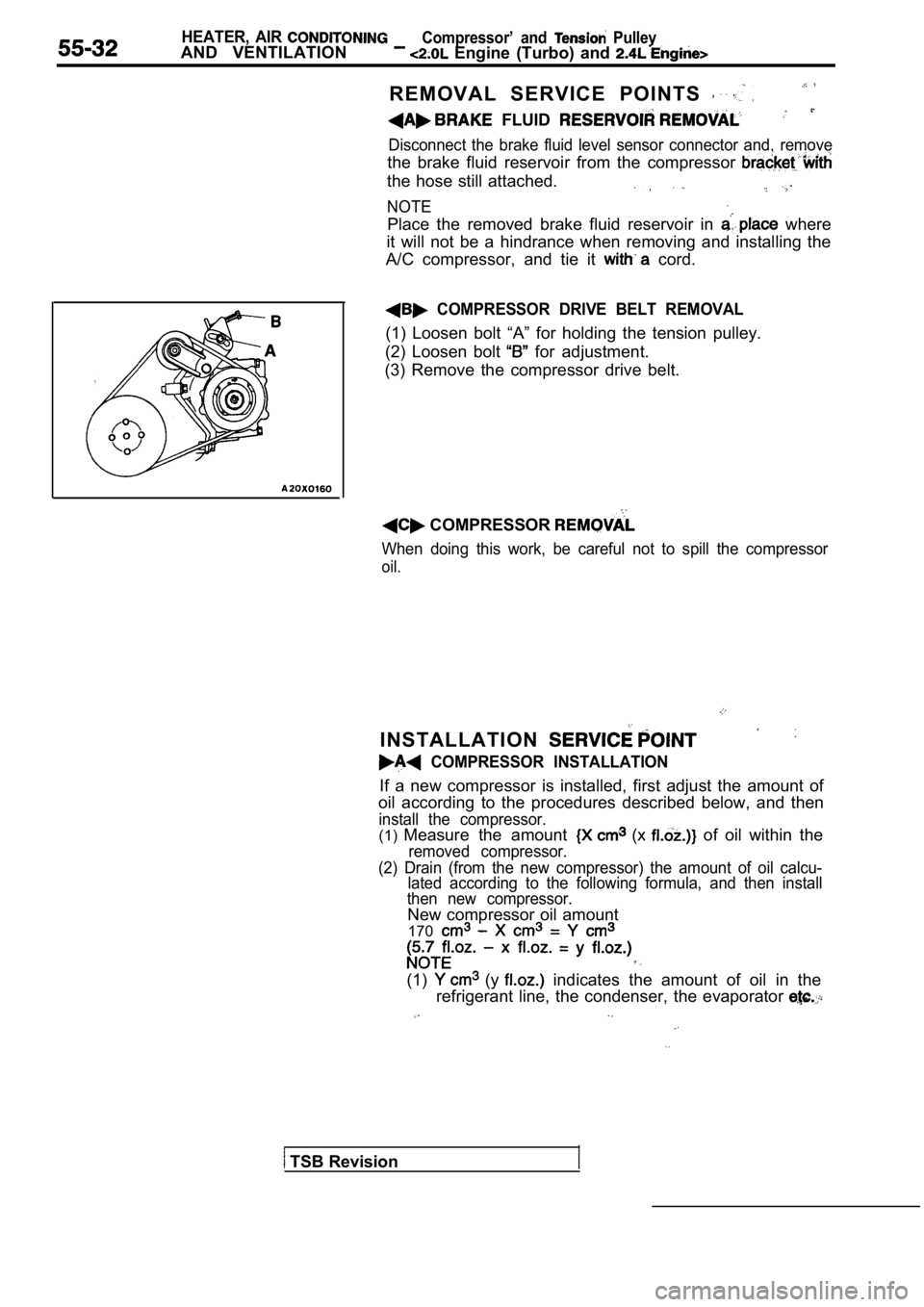
COMPRESSOR DRIVE BELT REMOVAL
(1) Loosen bolt “A” for holding the tension pulley.
(2) Loosen bolt
for adjustment.
(3) Remove the compressor drive belt.
COMPRESSOR
When doing this work, be careful not to spill the c ompressor
oil.
TSB Revision
Page 2073 of 2103
HEATER, AIR Compressor
AND VENTILATION Engine (Turbo) and
When the following’ parts as
compressor, subtract the rated oil amount of the each
part from discharge from the new
compressor.
Quantity
Evaporator: 60 (2.03
Condenser: 15
Suction hose: 10
Receiver: 10
INSPECTION55200420047
lChecking for heat damage of the tension pulley.
lCheck for excessive play or deflection of the tensi on pulley.
lCheck for unusual wear of the tension pulley.
Check for hardening of the compressor drive belt.
lCheck for unusual wear or abrasion of the compresso r
drive belt.
TSB Revision
Page 2075 of 2103
HEATER, AIR Compressor and Tension Pulley
AND VENTILATION Engine (Turbo) and Engine>55-35
Clutch coil
Clutch coilSnap-ringI
Crankshaft
Serration notch
NUT REMOVAL
Use the special tools to remove the nut.
REASSEMBLY SERVICE POINTS
CLUTCH COIL INSTALLATION
When installing the clutch coil to the A/C compress
or body,
install so that the pin hole of the A/C compressor body and
the clutch coil projection are aligned.
SNAP RING INSTALLATION
Install the snap ring so that the tapered surface i s at the
outer side.
ARMATURE PLATE INSTALLATION
Align the mating mark of the crankshaft and the mating
mark of the armature plate, and then’ fit them toge ther.
NUT INSTALLATION
Use the special tools to remove the nut.
TSB Revision
Page 2076 of 2103

55-36HEATER, AIR
AND VENTILATION
Compressor and Tension Pulley
Engine (Turbo) and
Feeler gauge
temperature
switch
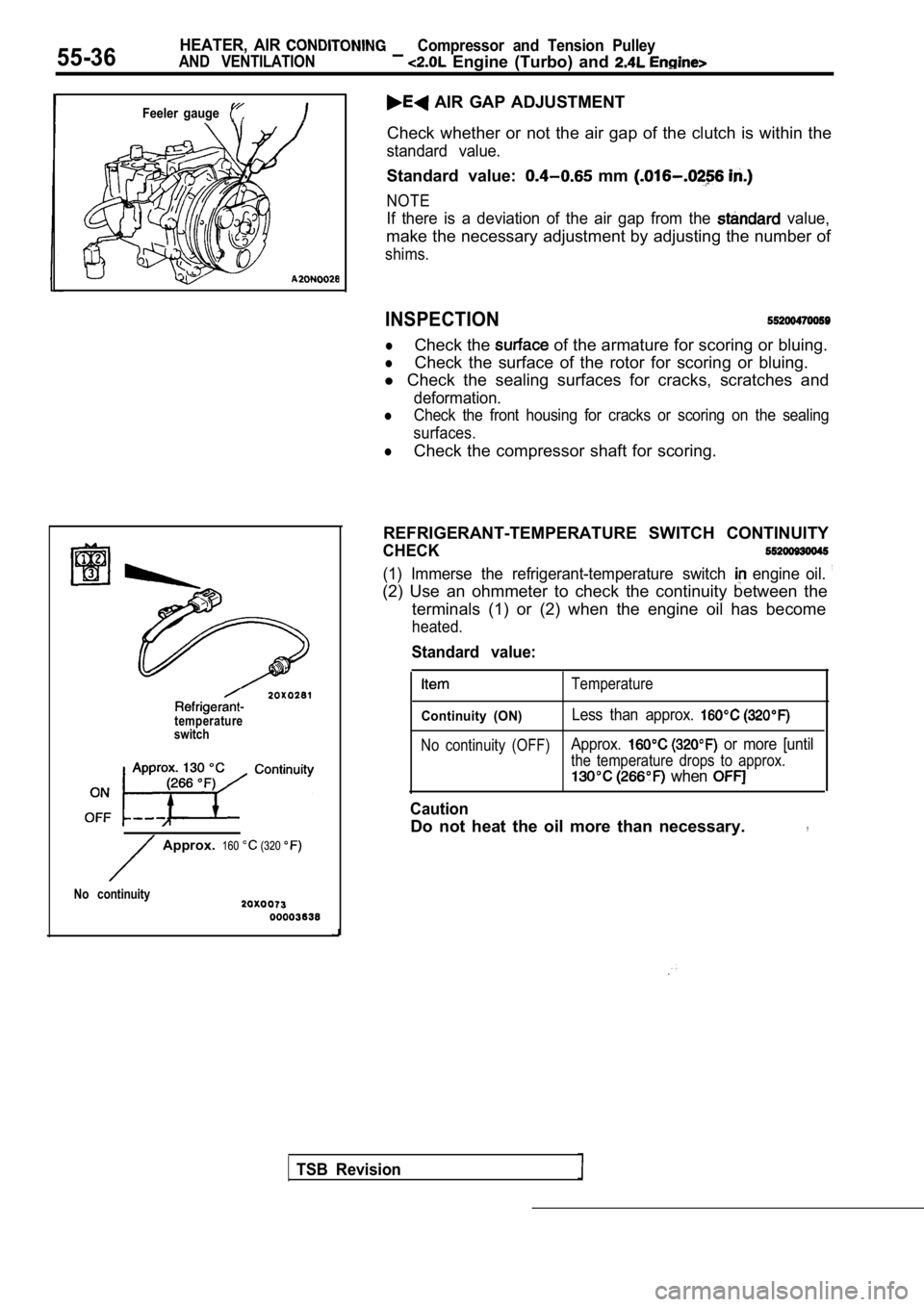
AIR GAP ADJUSTMENT
Check whether or not the air gap of the clutch is w ithin the
standard value.
Standard value: mm
NOTE
If there is a deviation of the air gap from the value,
make the necessary adjustment by adjusting the numb er of
shims.
INSPECTION
lCheck the of the armature for scoring or bluing.
lCheck the surface of the rotor for scoring or bluing.
l Check the sealing surfaces for cracks, scratches an d
deformation.
lCheck the front housing for cracks or scoring on the sealing
surfaces.
lCheck the compressor shaft for scoring.
REFRIGERANT-TEMPERATURE SWITCH CONTINUITY
CHECK
(1) Immerse the refrigerant-temperature switch engine oil.
(2) Use an ohmmeter to check the continuity between the
terminals (1) or (2) when the engine oil has become
heated.
TSB Revision
Approx. 160 (320
No continuity
Standard value:
Temperature
Continuity (ON)Less than approx.
No continuity (OFF)Approx. or more [until
the temperature drops to approx.
when
Caution
Do not heat the oil more than necessary.,