Page 95 of 2103
ENGINE Cylinder Head Gasket
i n . )
Mating marks
(2) Apply specified sealant to the thermostat case
in the places shown in the illustration.
Specified
MITSUBISHI GENUINE PART equiva-
lent
(3) Apply a small amount of water to the O-ring water
inlet pipe, and then press the thermostat case
into the water inlet pipe.
(4) Tighten the thermostat case assembly mounting b olts.
(5) Tighten the water inlet pipe bolts.
RADIATOR LOWER HOSE/RADIATOR UPPER HOSE CONNECTION
(1) Insert each hose as far as the projection of th e water
outlet fitting or water inlet fitting.
(2) Align the mating marks on the radiator hose and hose
clamp, and then connect the radiator hose.
HIGH-PRESSURE FUEL CONNECTION
When connecting the fuel hose to the fuel rail,
apply a small amount of clean engine oil to the hos e union
and then insert, being careful not to damage the
Caution
Do not let engine oil get into the fuel rail.
TSB Revision
Page 98 of 2103

ENGINE Timing Belt
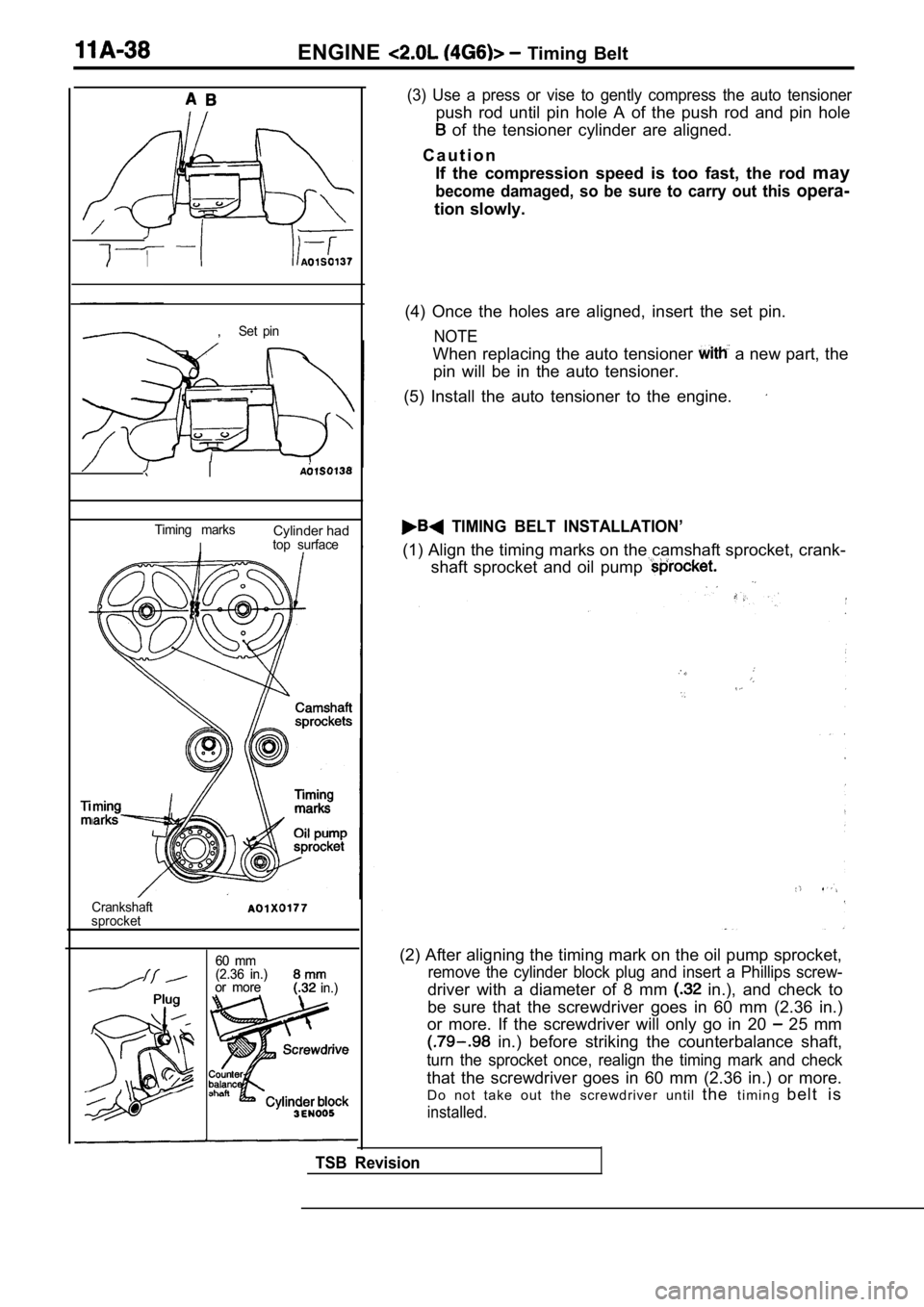
,Set pin
I
Timing marksCylinder had
Itop surface
Crankshaft
sprocket
60 mm
60 mm
(2.36 in.)
(2.36 in.)
or more
or more in.) in.)
(3) Use a press or vise to gently compress the auto tensioner
push rod until pin hole A of the push rod and pin hole
of the tensioner cylinder are aligned.
C a u t i o n If the compression speed is too fast, the rod may
become damaged, so be sure to carry out this opera-
tion slowly.
(4) Once the holes are aligned, insert the set pin.
NOTE
When replacing the auto tensioner a new part, the
pin will be in the auto tensioner.
(5) Install the auto tensioner to the engine.
TIMING BELT INSTALLATION’
(1) Align the timing marks on the camshaft sprocket , crank-
shaft sprocket and oil pump
(2) After aligning the timing mark on the oil pump sprocket,
remove the cylinder block plug and insert a Phillips screw-
driver with a diameter of 8 mm in.), and check to
be sure that the screwdriver goes in 60 mm (2.36 in .)
or more. If the screwdriver will only go in 20
25 mm
in.) before striking the counterbalance shaft,
turn the sprocket once, realign the timing mark and check
that the screwdriver goes in 60 mm (2.36 in.) or mo re.
Do not take out the screwdriver until thet i m i n g b e l t i s
installed.
TSB Revision
Page 99 of 2103

E N G I N E
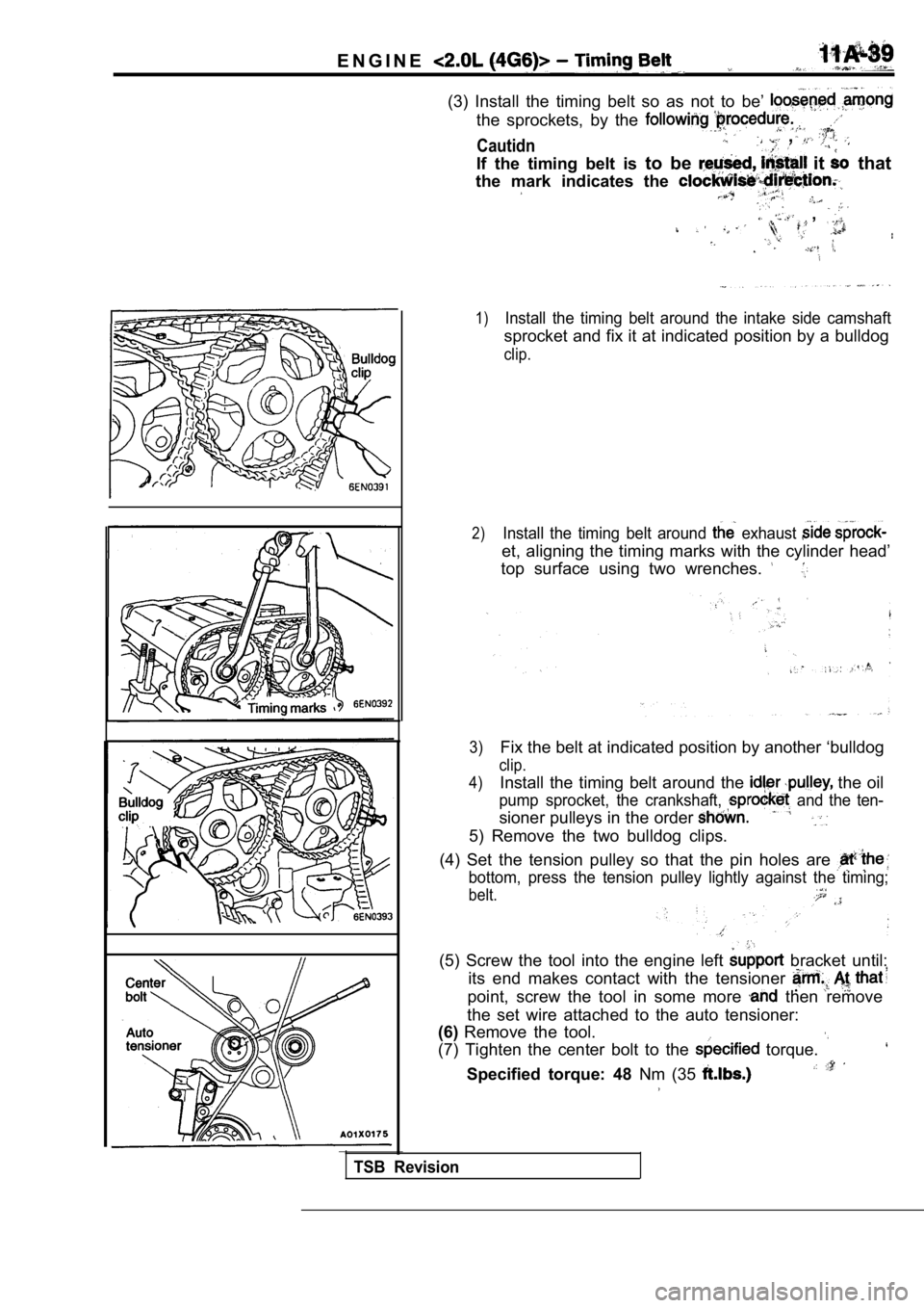
(3) Install the timing belt so as not to be’
the sprockets, by the
Cautidn ,
If the timing belt is to be it that
the mark indicates the
,
1)Install the timing belt around the intake side cams haft
sprocket and fix it at indicated position by a bulldog
clip.
2)Install the timing belt around exhaust
et, aligning the timing marks with the cylinder hea d’
top surface using two wrenches.
3)Fix the belt at indicated position by another ‘bull dog
clip.
4)
Install the timing belt around the the oil
pump sprocket, the crankshaft, and the ten-
sioner pulleys in the order
5) Remove the two bulldog clips.
(4) Set the tension pulley so that the pin holes ar e
bottom, press the tension pulley lightly against the timing;
belt.
(5) Screw the tool into the engine left bracket until:
its end makes contact with the tensioner
point, screw the tool in some more then remove
the set wire attached to the auto tensioner:
(6) Remove the tool.
(7) Tighten the center bolt to the
torque.
Specified torque: 48 Nm (35
TSB Revision
Page 101 of 2103
ENGINE Timing
TIMING BELT
REMOVAL AND INSTALLATION
(Engine oil) Nm
Removal steps1. Timing belt (Refer to
2. Crankshaft sprocket 3. Crankshaft sensing blade l Timing belt tension adjustment
4. Timing belt tensioner 5. Timing belt
__
REMOVAL SERVICE POINTS
CRANKSHAFT SPROCKET
(1) Use thespecial tool to remove the bolt,
(2) Use the special tool to remove the crankshaft
TSB Revision
Page 103 of 2103
ENGINE Timing Belt
CRANKSHAFT SENSING BLADE INSTALLATION
When installing, make sure the direction is correct. See figure.
CRANKSHAFT SPROCKET INSTALLATION
Use the special tool to install the crankshaft spro cket and
bolt.
NOTE
Apply the minimum amount of engine oil to the beari ng surface
and thread of the crankshaft bolt.
Revision
Page 105 of 2103

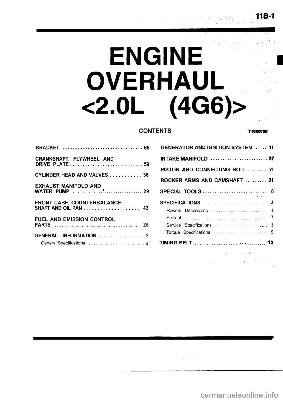
CONTENTS
BRACKET65
CRANKSHAFT, FLYWHEEL ANDDRIVE PLATE
. . . . . . . . . . . . . . . . . . . . . . . . . . . . .59
CYLINDER HEAD AND VALVES . . . . . . . . . . . 36
EXHAUST MANIFOLD AND
WATER PUMP. . . . . . . * . . . . . . . . . . . . . . . . . . . .29
FRONT CASE, COUNTERBALANCE
SHAFT AND OIL PAN . . . . . . . . . . . . . . . . . . . . . 42
FUEL AND EMISSION CONTROL
PARTS. . . . . . . . . . . . . . . . . . . . . . . . . . . . . . . . . . .25
GENERAL INFORMATION. . . . . . . . . . . . . . . . . .2
General Specifications . . . . . . . . . . . . . . . . . . , . . . . .2
GENERATOR IGNITION SYSTEM. . . . .11
INTAKE MANIFOLD. . . . . . . . . . . . . . . . . . . . . .
PISTON AND CONNECTING ROD..
. . . . . . . .51
ROCKER ARMS AND CAMSHAFT. . . . . . . .
SPECIAL TOOLS
. . . . . . . . . . . . . . . . . . . . . . . . . . .8
SPECIFICATIONS. . . . . . . . . . . . . . . . . . . . . . . . . .3
Rework Dimensions. . . . . . . . . . . . . . . . . . . . . . . . . .4
Sealant. . . . . . . . . . . . . . . . . . . . . . . . . . . . . . . . . .. . ..
Service Specifications. . . . . . . . . . . . . . . . . . . ....3
Torque Specifications. . . . . . . . . . . . . . . . . . . . . . . . . . . .5
TIMING BELT
. . . . . . . . . . . . . . . . . .. . . . . . . . .
,
Page 106 of 2103
ENGINE OVERHAUL General Information
GENERAL INFORMATION
GENERAL SPECIFICATIONS
Descriptions
Number of cylinders
Combustion chamber
Total displacement
. . .Specifications
“in-line DOHC
4
type
1,997 (121.9)
Cylinder bore mm (in.)
Piston stroke mm (in.)
(3.35)
88.0 (3.46)
Compression ratio 8.5
Valve, timingIntake valve
Opens (BTDC)2 1 ”
Exhaust valve Closes (ABDC)
51
Opens (BBDC)
57”
‘Closes (ATDC)
Lubrication system Pressure feed, full-flow filtrationI
Oil pump type
Cooling system
Water pump type EGR type
I
Involute gear type
Water-cooled . .
Centrifugal impeller type
Single type,
TSB Revision
Injector type and number
Injector identification number
Fuel regulated pressure
(psi)
4
,
(42.7) .
Throttle bore mm (in.)
Throttle position sensor Closed throttle position switch 54 (2.13)
Variable resistor type
Contact type
Page 107 of 2103

ENGINE OVERHAUL ‘Specifications
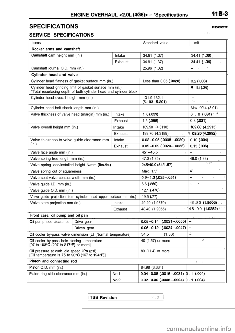
SPECIFICATIONS
SERVICE SPECIFICATIONS
Rocker arms and camshaft
cam height mm (in.)
Camshaft journal O.D. mm (in.)
Cylinder head and valve
Standard valueLimit
Intake 34.91 (1.37) 34.41
Exhaust 34.91 (1.37) 34.41
25.96 (1.02)
Cylinder head flatness of gasket surface mm (in.) Le ss than 0.05 0.2
Cylinder head grinding limit of gasket surface mm (in.)l 9.2
*Total resurfacing depth of both cylinder head and cylinder block
Cylinder head overall height mm (in.) 131.9-132.1
Cylinder head bolt shank length mm (in.) Max. (3.91)
Valve thickness of valve head (margin) mm (in.) Intake
16 . 8
Exhaust1.5 0.8
Valve overall height mm (in.)Intake109.50 (4.3110) (4.2913)
Exhaust 199.70 (4.3189)
.
Valve thickness to valve guide clearance mmIntake0.10
(in.)Exhaust0.15
Valve face angle mm (in.),
Valve spring free length mm (in.) 47.0 (1.85) 46.0 (1
.83)
Valve spring load/installed height N/mm
Valve spring out of squarenessMax. 1.5”4”
Valve seat valve contact width mm (in.)
Valve guide I.D. mm (in.) 6.6
Valve guide mm (in.)12.1
Valve guide projection from cylinder head upper sur
face mm (in.)19.5
Valve stem projection mm (in.) Intake 49.20 (1.9370)4 9 . 8 0 .
Exhaust48.40 (1.9055) ‘ 4 8 . 9 0
Front case, oilpump and oilp a n
pump side clearance Drive gear
Driven gear
cooler by-pass valve dimension (L) [Normal tempera
ture]34.5 (1.36)
cooler by-pass hole closing temperature 40 (1.57) or more
97 to (207 to or more]
pressure at curb idle speed (psi)80 (11.4) or more
Oil temperature is 75 to (167 to
and connecting rod ,
O.D. mm (in.)
84.98 (3.334)
ring side clearance mm (in.) 0 . 1
0 . 1
TSB Revision