Page 184 of 2103

ENGINE Engine
ENGINE ASSEMBLY
REMOVAL AND INSTALLATION
Pm-removal Operationl Fuel Line Pressure Releasing(Refer to GROUP On-vehicle Service.)l Hood Removall Engine Coolant Draining
(Refer to GROUP 00 Maintenance Service.)l Transaxle Assembly Removal Refer to GROUP Transaxle Assembly.) Refer to GROUP Transaxle Assembly.)lRadiator Removal (Refer to GROUP 14 Radiator.)l Under Cover Removal(Refer to GROUP 42 Under Cover.)
39 Nm29
39 Nm29
Post-installation Operationl Radiator Installation (Refer to GROUP 14 Radiator.)l Transaxle Assembly Installation Refer to GROUP Transaxle Assembly.) Refer to GROUP Assembly.)l Engine Coolant Supplying
(Refer to GROUP 00 Maintenance Service.)l Hood Installationl Accelerator Cable Adjustment(Refer to GROUP 17 On-vehicle l Under Cover Installation
(Refer to GROUP 42 Under-Cover.)l Drive Belt Tension Adjustment
9
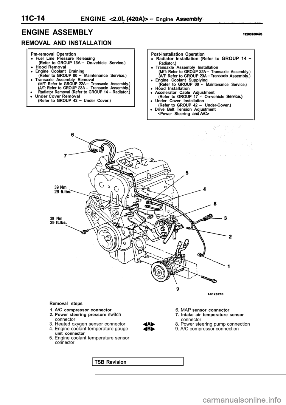
Removal steps
1. compressor connector
2. Power steering pressure switch
connector3. Heated oxygen sensor connector
4. Engine coolant temperature gauge
unit connector
6. MAP sensor connector
7. Intake air temperature sensor
connector8. Power steering pump connection
9. A/C compressor connection
5. Engine coolant temperature sensor
connector
TSB Revision
Page 199 of 2103
Cylinder Head
CYLINDER HEAD GASKET
REMOVAL AND INSTALLATION
Operation
lFuel Line Pressure Releasing (Refer to GROUP On-vehicle Service.)l Engine Coolant Draining(Refer to GROUP 00 Maintenance Service.)l Engine Oil Draining(Refer to GROUP 00 Maintenance Service.)l Air Cleaner Removal
6
Post-installation Operationl Air Cleaner Installationl Engine Oil (Refer to GROU00 Maintenance Service.)l Engine Coolant Supplying(Refer to GROUP 00 Maintenance Service.)lAccelerator Cable Adjustment (Refer to GROUP
17 On-vehicle Service.)
Removal steps
1. NC compressor connector
2. Power steering pressure switch
connector3. Heated oxygen sensor connector
4. Engine coolant temperature gauge unit connector
connector6. MAP
TSBRevision
Page 283 of 2103

Engine Assembly11
ENGINE ASSEMBLY
REMOVAL AND INSTALLATION
Pm-removal Operationl Fuel Line Pressure Releasing(Refer to GROUP On-vehicle Service.)l Hood Removall Engine Coolant Draining(Refer to GROUP 00 Maintenance l Transaxle Assembly Removal Refer to GROUP Assembly.) Refer to GROUP Transaxle Assembly.)lRadiator Removal (Refer to GROUP 14 -Radiator.)l Under Cover Removal(Refer to GROUP 42 Under Cover.)
1
22Nm16
6
28Nm
Post-installation Operationl Radiator Installation(Refer to GROUP 14 Radiator.)l Transaxle Assembly Installation Refer to GROUP Transaxle Assembly.) Refer to GROUP -Transaxle Assembly.)l Engine Coolant Supplying(Refer to GROUP 00 Maintenance Service.)l Hood Installationl Accelerator Cable Adjustment (Refer to GROUP 17 On-vehicle Service.)l Under Cover Installation(Refer to GROUP 42 Under Cover.)l Drive Belt Tension Adjustment
28Nm21
21 Nm
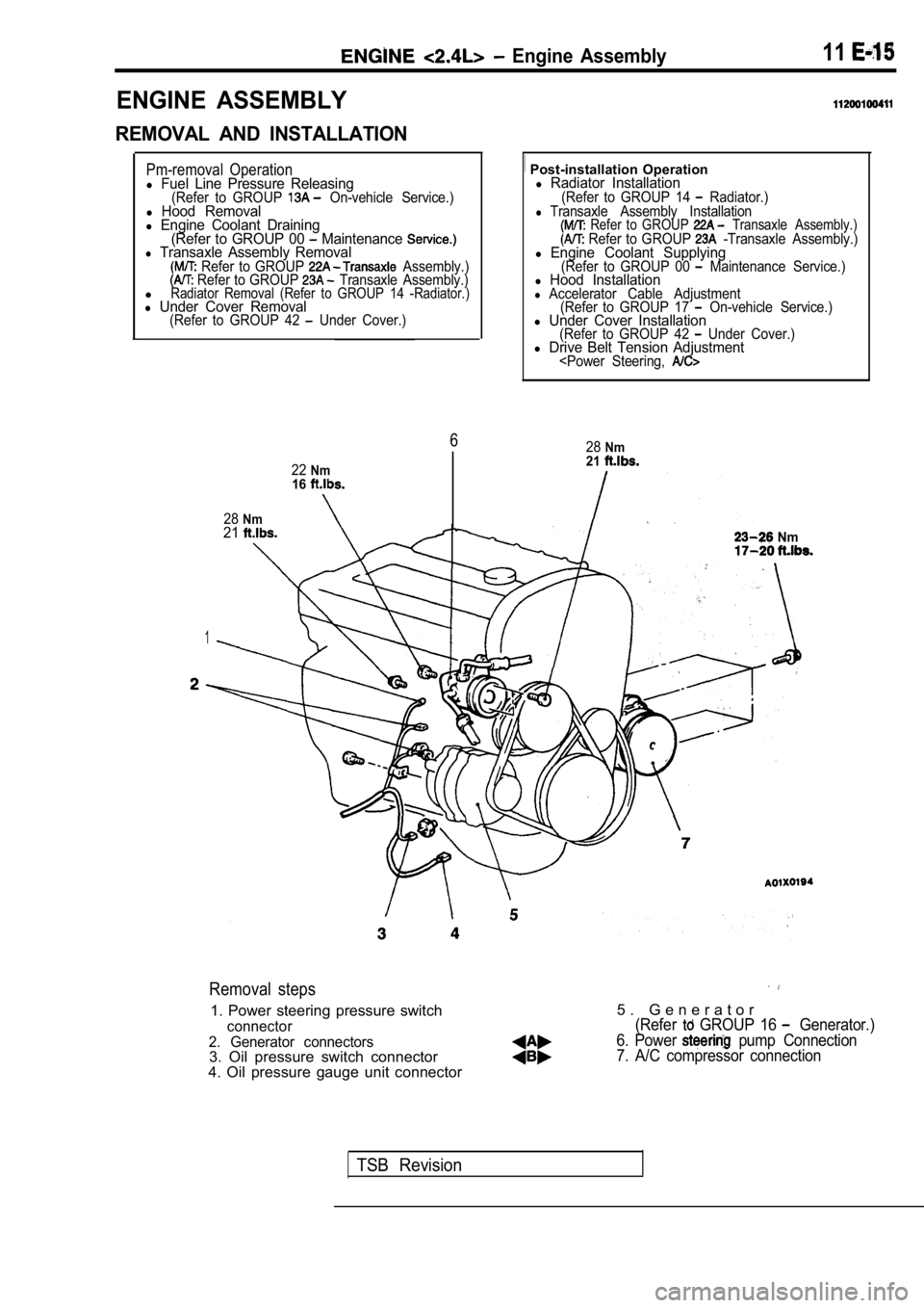
Removal steps
1. Power steering pressure switch
connector
2. Generator connectors
3. Oil pressure switch connector
4. Oil pressure gauge unit connector
5 . G e n e r a t o r(Refer GROUP 16 Generator.)
6. Power
pump Connection
7. A/C compressor connection
TSB Revision
Page 292 of 2103
11ENGINE Pan and Oil Screen
OIL PAN AND OIL SCREEN
REMOVAL AND INSTALLATION
and Post-installation OperationlEngine Oil Draining and Supplying
(Refer to GROUP 00 Maintenance service.)l Oil Level Gauge Removal and InstallationlFront Exhaust Pipe Removal and Installation
(Refer to GROUP 15 Exhaust Pipe and MainMuffler.)
TSB Revision
5
Specified sealant:
MITSUBISHI PART
or equivalent
739 Nm
229
0 0 0 0 0 2 4 5
Removal steps
1. Bell housing cover
2. Drain plug
3. G a s k e t 4. Oil p a n5. Oil screen
Page 377 of 2103
ENGINE LUBRICATION Oil Cooler
ENGINE OIL COOLER 12100130117
REMOVAL AND INSTALLATION
Operationl Engine Coolant Draining(Refer to GROUP 00 Maintenance
Engine oil
Engine Oil Checking and Supplying
2
Removal steps
1. Oil filter
2. Water hose connection
3. Oil cooler bolt
4. Engine oil cooler
Oil filter bracket
Stopper
Engine oil cooler
INSTALLATION SERVICE POINT
ENGINE OIL COOLER INSTALLATION
the stopper into the groove of the oil filter bracket,
and then tighten the oil cooler bolt.
TSB Revision
Page 697 of 2103

ENGINE COOLING On-vehicle Service
Engine (Turbo) and
ON-VEHICLE SERVICE
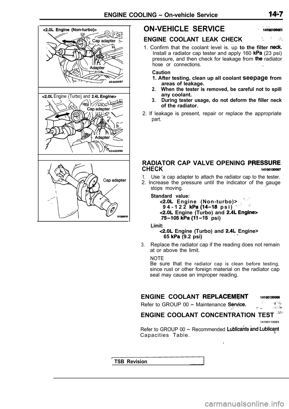
ENGINE COOLANT LEAK CHECK
1. Confirm that the coolant level is. up to the filter
Install a radiator cap tester and apply 160 (23 psi)
pressure, and then check for leakage from
radiator
hose or connections.
Caution
1. After testing, clean up all coolant seepagefrom
areas of leakage.
2.When the tester is removed, be careful not to spill
any coolant.
3.During tester usage, do not deform the filler neck
of the radiator.
2. If leakage is present, repair or replace the app ropriate
part.
RADIATOR CAP VALVE OPENING
CHECK
1.Use ‘a cap adapter to attach the radiator cap to the tester.
2. Increase the pressure until the indicator of the gauge
stops moving..
Standard value:
E n g i n e ( N o n - t u r b o ) >
9 4 - 1 2 2 p s i )
Engine (Turbo) and
psi)
Limit:
Engine (Turbo) and Engine>
65
(9.2 psi)
3.Replace the radiator cap if the reading does not re main
at or above the limit.
NOTE
Be sure that the radiator cap is clean before testing,
since rust or other foreign material on the radiato r cap
seal may cause an improper reading.
ENGINE COOLANT
Refer to GROUP 00 Maintenance
ENGINE COOLANT CONCENTRATION TEST
1 4 1 0 0 1 1 0 0 8 5
Refer to GROUP 00 Recommended
C a p a c i t i e s T a b l e . ,
TSB Revision
Page 698 of 2103
14-8ENGINE COOLING, Radiator
RADIATOR
REMOVAL AND INSTALLATION
Engine (Non-turbo)>
Operationl Engine Coolant Draining (Refer to GROUP 00 Maintenance Service.)
2
12 Nm6.7
Radiator removal steps1. Drain plug
2. Radiator cap
3. Overflow tube
4.
tank
5. Reserve tank bracket
6. upper hose 7. h o s e
8. Transaxle cooler hose, tion
10. Radiator assembly
11. Transaxle fluid cooler hose and pipe assembly
12. Lower insulator
13.Condenser fan motor assembly
14.Radiator fan motor assembly15. Fan
16. Radiator fan motor
17. Shroud
Radiator fan motor removal steps
11. Transaxle fluid cooler hose and pipe assembly
with fan motor assembly
Radiator fan motor17. Shroud
TSB Revision
Page 699 of 2103
ENGINE
Engine (Turbo)>
Pre-removal OperationlEngine Coolant Draining (Refer to GROUP 00 Maintenance Service.)
Post-installation.
lEngine Coolant Supplying and GROUP 00 l A/T Fluid Checking and Refilling if with (Refer to GROUP 00 Maintenance
8.710
6
Radiator removal steps
1. Drain plug
2. Radiator cap
3. Overflow tube
4. Reserve tank 5. Reserve tank bracket
u p p e r h o s e 8. Radiator lower hose 9. Transaxle cooler hose and assembly
13. Condenser fan motor assembly
fan motor assembly
Radiator fan motor
17. Shroud
Radiator fan motor removal steps
Transaxle fluid hose and
pipe. with fan motor assembly
f a n 17.
.
.
TSB