Page 685 of 2103
FUEL SUPPLY Fuel Tank
Valve closed
Valve opened
Toport A To
INSPECTION
FUEL TANK FILLER TUBE
Engine (Non-turbo)
(1) Connect a clean rubber hose to the port
tank filler tube assembly.
(2) Blow air into the hose. Check that the air flow s out of
the port B.
(3) Use a screwdriver or similartool to close the valve. Blow
air into the hose in this condition. Check that the
not flow out of the port B.,
FUEL TANK DIFFERENTIAL PRESSURE SENSOR
CHECK
Engine>
(1) Disconnect the fuel tank differential
connector and connect the special tool
terminals of the disconnected connector.
(2) Turn the ignition switch to ON and take a readi ng of
the following output voltage. Between terminals (2)
(3)
Standard value: 2.0 3.0
FUEL CUT OFF VALVE CHECK
If the sound of the float valve moving (knocking so und) can
be heard when the valve assembly is gently shaken u p and
down, then the valve is okay.
FUEL GAUGE UNIT CHECKRefer to GROUP 54
Combination Meter.
TSB Revision
Page 728 of 2103

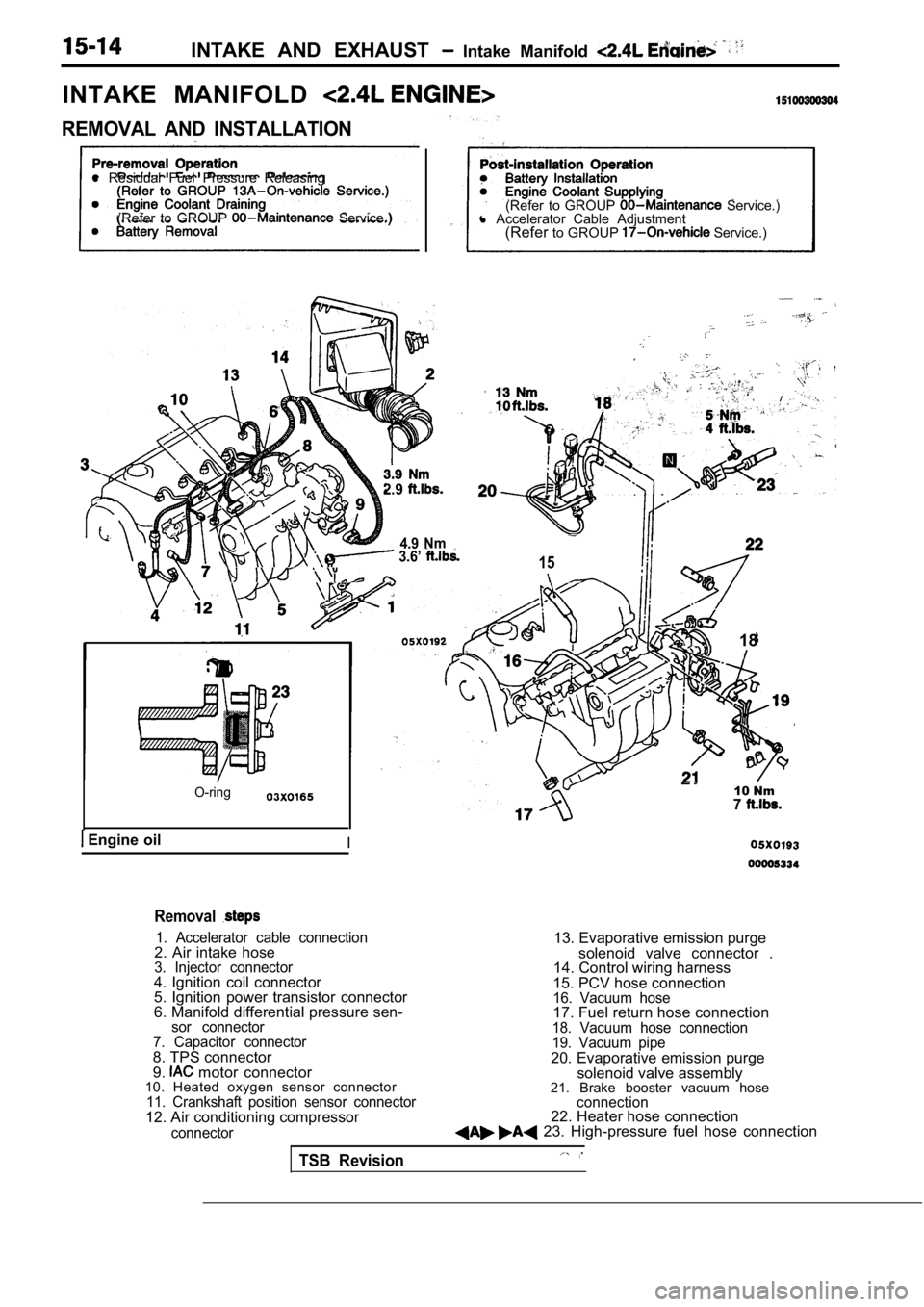
INTAKE AND EXHAUST Intake Manifold
INTAKE MANIFOLD
REMOVAL AND INSTALLATION
l Residual Fuel Pressure Releasing
(Refer to GROUP
Service.) (Refer to GROUP Service.)
l Accelerator Cable Adjustment
(Refer to GROUP
Service.)
2.9
4.9 Nm 3.6’ 15
O-ring
Engine oilI
18
10 Nm7
Removal
1. Accelerator cable connection2. Air intake hose3. Injector connector4. Ignition coil connector
5. Ignition power transistor connector
6. Manifold differential pressure sen-
sor connector
7. Capacitor connector
8. TPS connector
9. motor connector
10. Heated oxygen sensor connector
11. Crankshaft position sensor connector12. Air conditioning compressor
connector
13. Evaporative emission purge
solenoid valve connector .
14. Control wiring harness
15. PCV hose connection
16. Vacuum hose17. Fuel return hose connection18. Vacuum hose connection
19. Vacuum pipe
20. Evaporative emission purge solenoid valve assembly
21. Brake booster vacuum hose
connection22. Heater hose connection 23. High-pressure fuel hose connection
TSB Revision
Page 820 of 2103

(Turbo) and Engine>
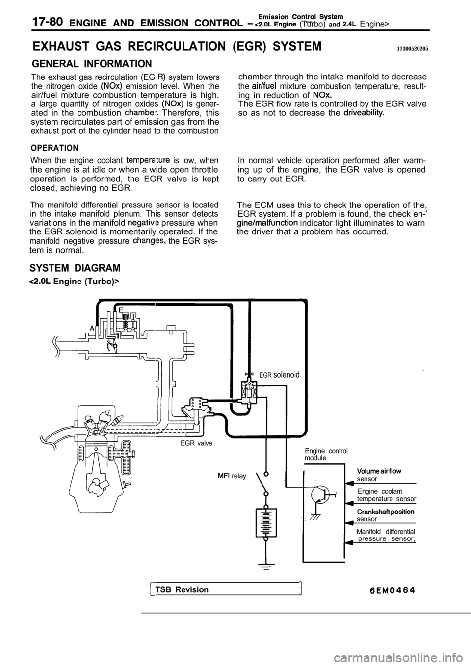
EXHAUST GAS RECIRCULATION
GENERAL INFORMATION
The exhaust gas recirculation (EG system lowers
the nitrogen oxide
emission level. When the
air/fuel mixture combustion temperature is high,
a large quantity of nitrogen oxides is gener-
ated in the combustion Therefore, this
system recirculates part of emission gas from the
exhaust port of the cylinder head to the combustion
OPERATION
When the engine coolant is low, when
the engine is at idle or when a wide open throttle
operation is performed, the EGR valve is kept
closed, achieving no EGR.
The manifold differential pressure sensor is locate d
in the intake manifold plenum. This sensor detects
variations in the manifold pressure when
the EGR solenoid is momentarily operated. If the
manifold negative pressure the EGR sys-
tem is normal.
SYSTEM DIAGRAM
Engine (Turbo)>
(EGR) SYSTEM17300520205
chamber through the intake manifold to decrease
the mixture combustion temperature, result-
ing in reduction of
The EGR flow rate is controlled by the EGR valve
so as not to decrease the
In normal vehicle operation performed after warm-
ing up of the engine, the EGR valve is opened
to carry out EGR.
The ECM uses this to check the operation of the, EGR system. If a problem is found, the check en-’
indicator light illuminates to warn
the driver that a problem has occurred.
EGR valve
relay
EGRsolenoid
Engine control
module
Isensor
Engine coolant
temperature sensor
sensor
Manifold differential
TSB Revision
pressure sensor,
Page 821 of 2103
ENGINE AND EMISSION CONTROL Engine (Turbo) end
Engine>
COMPONENT LOCATION
Engine (Turbo)>
EGR solenoid
Manifold differential pressure sensor
relayEngine
module
EGR valve
Page 822 of 2103
Engine (Turbo) and Engine>
Engine>
EGR solenoidEGR valve
Manifold differential pressure
TSB Revision
Page 860 of 2103
MANUAL TRANSAXLE
ENGINE (TURBO) AND General Information
GENERAL
The manual transaxles come in three models,
namely,
and These
axles are essentially the same as the previous
els.
FWD
Engine
Model
Applicable engine
floor shift
Gear ratio
3.166
1.833
1.240
0.896
0.731
Reverse3.166
Final
gearratio 3.625
gear
Engine (Turbo)
floor shift
3.090
1.833
1.217
0.888
0.741
3.166
4.153
Specifications
Model
Applicable engine
floor shift
Gear ratio
3.083
1.684
1.115
0.833
0.666
Reverse 3.166
Reduction ratio Primary
1.275
Front differential3.800
Transfer1.074
Speedometer gear ratio (driven/drive)
Revision
Page 863 of 2103
MANUAL TRANSAXLE
ENGINE (TURBO) Information
hh
Input shaft
Drive bevel gear
Driven
bevel
gear
ousing
speed synchronizer
gearassembly
, .
speed gearSub gear
speed gear. speed synchronizer
I I gear
differential coupling
Front output shaft
gear- -
Center shaft
TSB Revision
Front differential
Page 881 of 2103
MANUAL TRANSAXLE (NON-TURBO)> General
SECTIONAL VIEW
synchronizer
I
speed gear
speed gear
idler
,
speed gear
synchronizer
1 st synchronizer
1 st speed clear
Differential
TSB RevisionI