Page 1781 of 2103

STEERING On-vehicle”
TSB Revision
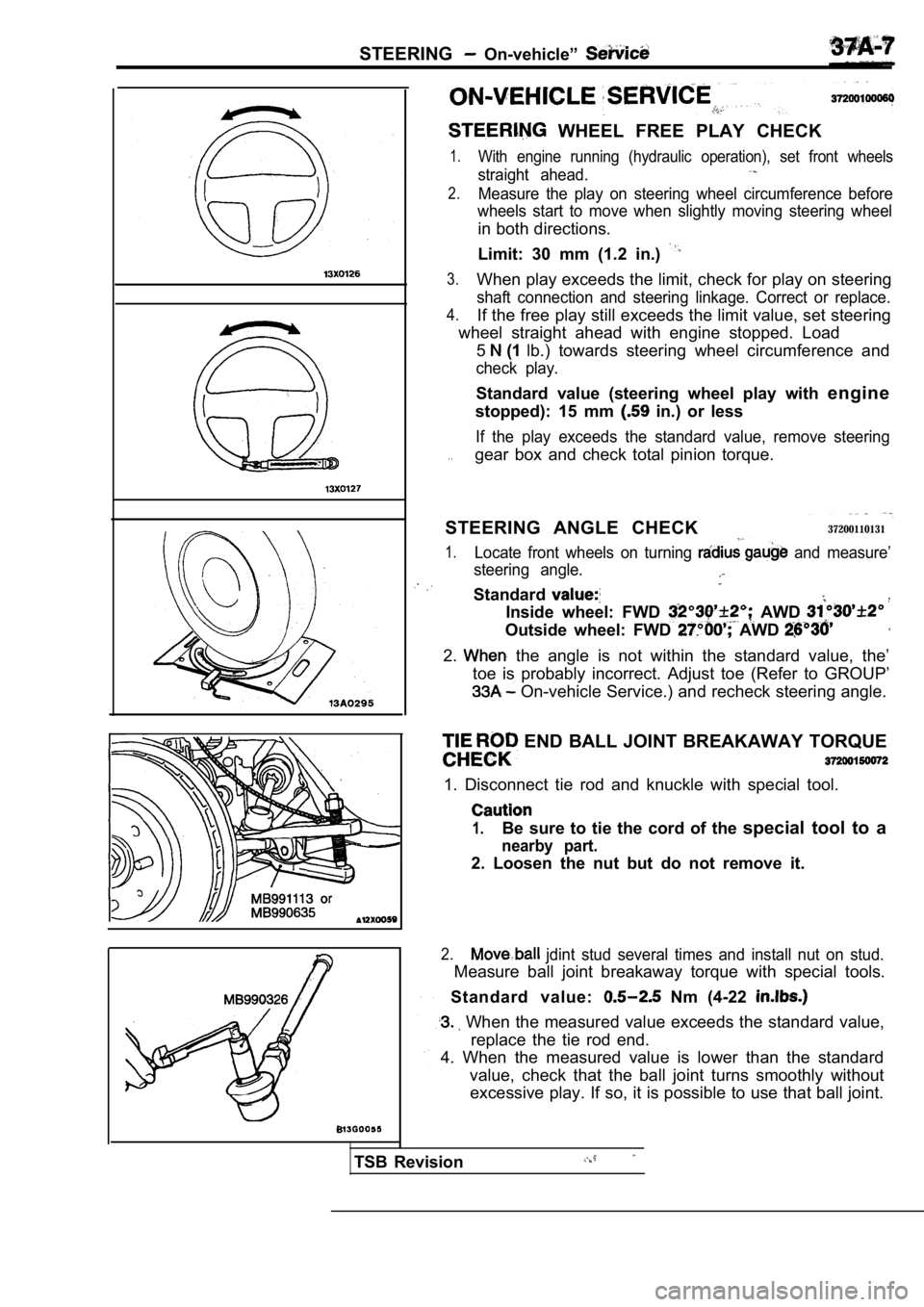
WHEEL FREE PLAY CHECK
1.With engine running (hydraulic operation), set front wheels
straight ahead.
2.Measure the play on steering wheel circumference be fore
wheels start to move when slightly moving steering wheel
in both directions.
Limit: 30 mm (1.2 in.)
3.When play exceeds the limit, check for play on steering
shaft connection and steering linkage. Correct or replace.
4.If the free play still exceeds the limit value, set steering
wheel straight ahead with engine stopped. Load
5
(1 lb.) towards steering wheel circumference and
check play.
Standard value (steering wheel play with engine
stopped): 15 mm
in.) or less
If the play exceeds the standard value, remove stee ring
. .gear box and check total pinion torque.
STEERING ANGLE CHECK
37200110131
1.Locate front wheels on turning and measure’
steering angle.
Standard
Inside wheel: FWD AWD
Outside wheel: FWD AWD
2. the angle is not within the standard value, the’
toe is probably incorrect. Adjust toe (Refer to GRO UP’
On-vehicle Service.) and recheck steering angle.
END BALL JOINT BREAKAWAY TORQUE
1. Disconnect tie rod and knuckle with special tool .
1.Be sure to tie the cord of the special tool to a
nearby part.
2. Loosen the nut but do not remove it.
2. jdint stud several times and install nut on stud.
Measure ball joint breakaway torque with special to ols.
Standard value:
Nm (4-22
When the measured value exceeds the standard value ,
replace the tie rod end.
4. When the measured value is lower than the standa rd
value, check that the ball joint turns smoothly wit hout
excessive play. If so, it is possible to use that b all joint.
Page 1784 of 2103

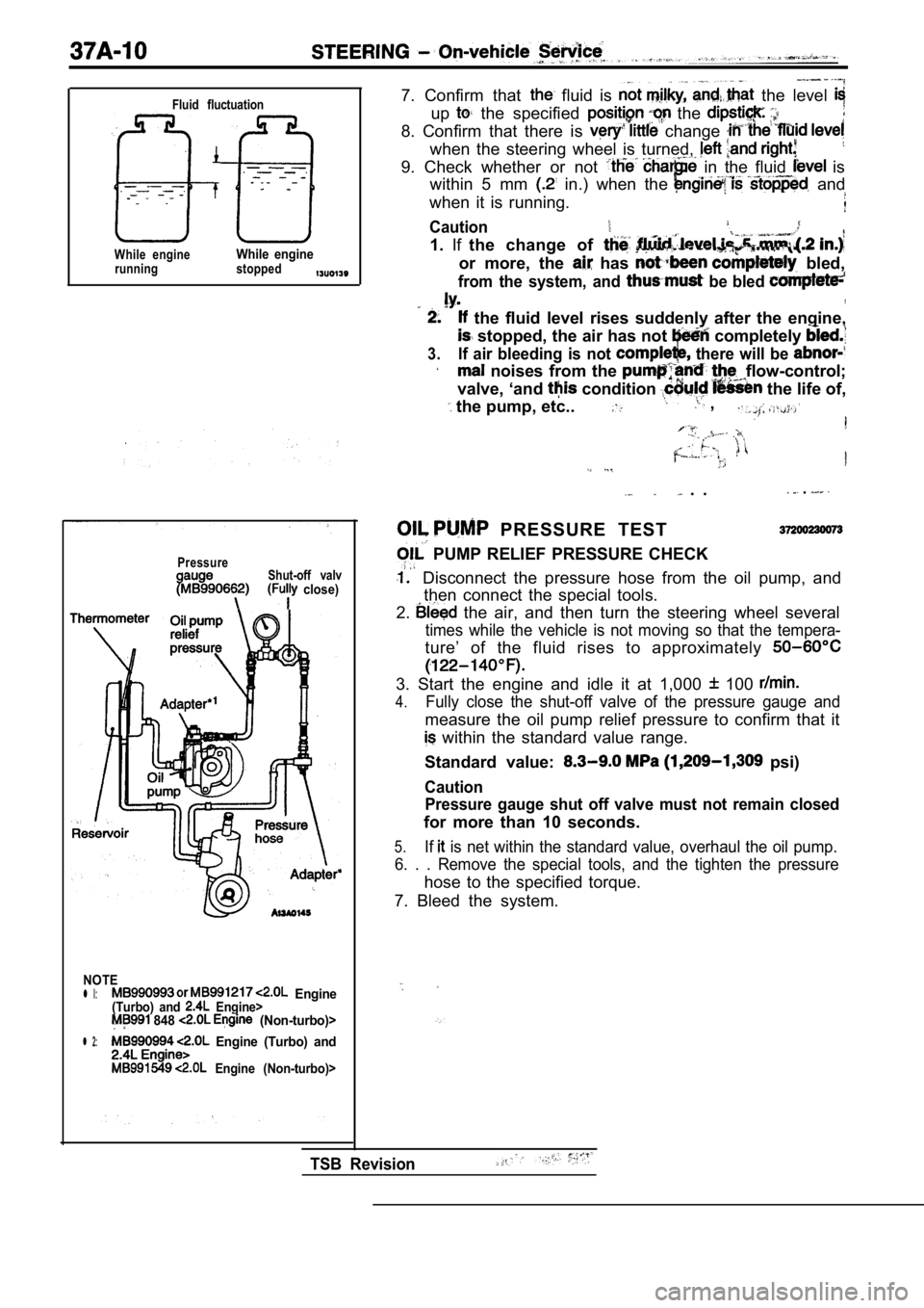
Fluid fluctuation
While engineWhile enginerunning stopped
PressureShut-off valv close)
NOTE
l l: Engine(Turbo) and Engine> 848 (Non-turbo)>
l 2: Engine (Turbo) and
Engine (Non-turbo)>
7. Confirm that fluid is the level
up the specified the
8. Confirm that there is change
when the steering wheel is turned,
9. Check whether or not in the fluid is
within 5 mm
in.) when the and
when it is running.
Caution
1. Ifthe change of
or more, the has bled,
from the system, and be bled ,
the fluid level rises suddenly after the engine,
stopped, the air has not completely
3.If air bleeding is not there will be
noises from the flow-control;
valve, ‘and
condition the life of,
the pump, etc.. ,
. . .
PRESSURE TEST
PUMP RELIEF PRESSURE CHECK
Disconnect the pressure hose from the oil pump, an d
then connect the special tools.
2.
the air, and then turn the steering wheel several
times while the vehicle is not moving so that the t empera-
ture’ of the fluid rises to approximately
3. Start the engine and idle it at 1,000 100
4.Fully close the shut-off valve of the pressure gaug e and
measure the oil pump relief pressure to confirm tha t it
within the standard value range.
Standard value:
psi)
Caution Pressure gauge shut off valve must not remain close d
for more than 10 seconds.
5.If is net within the standard value, overhaul the oil pump.
6. . . Remove the special tools, and the tighten th e pressure
hose to the specified torque.
7. Bleed the system.
TSB Revision
Page 1785 of 2103
STEERING On-vehicle’ Service
PressureShut-off valve(Fully open)
I
Thermometer
NOTE Engine
(Turbo) and
548 Engine (Non-turbo)>
l 2: Engine (Turbo) and
549 Engine (Non-turbo)>
. .. . ..
CHECKING
UNDER NO-LOAD
1. Disconnect. the pressure hose from the oil pump, and
then connect the special tools.
2. Bleed the air, and then turn the steering
several:
times the vehicle is not moving so that the tempera-
ture the fluid rises to approximately
3. the and idle it 100
4.Check whether or not the hydraulic pressure is
dard value when no-load conditions fully
opening the shut-off
of the pressure gauge.
value:
5.If it is not within the standard cause
is a malfunction of the oil
or so
6.
check these parts and repair
Remove the special tools, pressure
hose to the specified torque.
7. Bleed the system.
TSB Revision
Page 1786 of 2103
STEERING On-vehicle Service,.
Shut-off valve
Pressure gauge (Fully open)
I
Thermometer
NOTE
‘ 1 :(Turbo) and Engine> Engine (Non-turbo)>
l 2: Engine (Turbo) and Engine> 549 Engine (Non-turbo)>
STEERING GEAR RETENTION HYDRAULIC PRESSURE
CHECK
Disconnect the hose oil pump,
then connect the’ special tools.
2.Bleed the air, and then turn the steering wheel sev eral
times while the vehicle is moving so that
ture of the fluid rises a p p r o x i m a t e l y
3. Start the engine and it at 1,000 100
4. Fully open the shut-off valve of the pressure ga uge.
5.Turn the steering wheel all the way to the right;
then check whether or not the pressure
is the standard value.
Standard value:
6. not within the standard value; the steering
gear box. ,
Remeasure fluid pressure.:
7. Remove the special tools, and the tighten the pr essure
hose to the specified torque.
8. Bleed the system.
TSB Revision
Page 1787 of 2103
S T E E R I N G
POWER PRESSURE
Shut-off valve
Pressure
2.
3.
4.
Disconnect the from bump, and
then connect the special tools. Bleed the air, and then turn the
times while the is-not
ture of the fluid rises to
The engine should be idling.
5.
Disconnect the connection of the connector for the pres-
sure switch, and place an ohmmeter in position.
Gradually close the shut-off valve of the pressure gauge
and increase the hydraulic pressure then check
or not the hydraulic pressure that activates the sw itch
is the standard value.
Standard value:
(213-284 psi)
6.Gradually open the shut-off valve and reduce the hy draulic
pressure; then check whether or not the hydraulic p ressure
that deactivates the switch is the standard value.
Standard value: 0.8
(114 psi) or less
8.
Remove the special tools, and tighten’ the pressure
hose to the specified torque.
Bleed the, system.
NOTEl l or 217 Engine and (Non-turbo)>
l 2: Enaine (Turbo) and Engine> Engine (Non-turbo)>
TSB Revision
Page 1796 of 2103
S T E E R I N G
TSB Revision
T O T A L T O R Q U E C H E C K .
Using the special tools, rotate
of one rotation in approximately
the total. torque. , ,
Standard value: ,
[Change in torque: 0.4
NOTE.
When measuring, remove
Measure the pinion torque through
rack. .
the measured value is not- within the standard
adjust the rack support cover, and then
starting torque
al
If the pinion torque, be; the
standard, range by
the rack support cover, rack,
and any parts if
ROD SWING RESISTANCE CHECK
(1)
hard swings to the tie rod.
(2) Measure the tie rod swing resistance with a spr ing scale.
Standard value:
7.8-27
(1.8-6.2 Ibs.)
Nm (13-43
(3) When the measured value exceeds the standard va lue,
replace the tie rod assembly.
(4) When the measured value is lower than the stand ard
value, check that the ball joint swings smoothly wi thout
excessive play. If so, it is possible to use that b all joint.
.
Page 1797 of 2103
Power Steering Gear
DISASSEMBLY AND REASSEMBLY
6
22 Nm
Steering
Disassembly steps
1.Feed tube2.O-ring3. Tie rod end locking nut
4. Tie rod end assembly5.Bellows clip 6. Bellows band7.Bellows8.T i e r o d 9. Tab washer l Total pinion torque adjustment
10. Locking nut
11. Rack support cover
12. Rack support spring
13.Rack support
14. End plug15.Self-locking nut16. Valve housing assembly
17. Oil seal 18. Pinion and valve assembly
20. Bali bearing 21.
Oil seal22.Valve housing
23. 24. Rack stopper 25. Rack bushing
33.Oil seal
34. Back-up 35. housing
TSB Revision
Page 1804 of 2103
STEERING Power Steering Gear Box
Bellows band
Concave
PINION TORQUE ADJUSTMENT
(1) Position rack at its center. Tighten support
to 15 Nm (11
(2) in neutral position, clockwise one
seconds with special tool., rack
cover and adjust torque to the. standard
(3) Using the special tools, rotate the pinion gear at the
of one rotation in approximately 4 to 6 seconds to
the total pinion torque.
Standard value:
(6-12
[Change in torque: 0.4 Nm (3
Caution
1.When adjusting, set standard value at high-
est value.
2.Assure no ratcheting or operating,
rack towards the shaft direction.
NOTE
When it cannot be adjusted the specified return]
angle, check rack support cover components or repla ce.
(4) After adjusting, lock rack cover with lock nut.
ROD INSTALLATION
.
After installing tie rod to rack, fold
to tie rod notch.
end (2 locations)
ii
BELLOWS BAND INSTALLATION
(1) Touch pliers against the of the
band and the band.
TSBRevision