Page 1669 of 2103
BASIC SYSTEM Front
FRONT DISC BRAKE
REMOVAL AND ,
I1I Operation
l Brake Fluid DrainingPost-installation Operationl Brake Fluid Supplying
lBrake Line Bleeding (Refer to
I
88Nm6 5
Removal steps
1. Brake hose connection
2.Gasket assembly
INSTALLATION SERVICE
FRONT BRAKE ASSEMBLY INSTALLATION
Install the front brake assembly and measure the disc brake
drag torque. (Refer to
INSPECTION
Check the brake disc for damage.
TSB Revision
Page 1683 of 2103
BASIC BRAKE SYSTEM Rear Disc Brake
REAR DISC BRAKE
REMOVAL AND INSTALLATION
I
I OperationlLoosening Parking Brake Cable Adjusting Nut..
l Brake Fluid DrainingPost-installation ‘OperationlBrake Fluid Filling andAir(Refer to lParking Brake Lever Adjustment
(Refer to GROUP 36 On-vehicle Service.)
49-59
36-43
3
Removal steps
1. Brake hose connection 2. Rear brake assembly
3. Brake disc .
INSTALLATION SERVICE POINT
REAR BRAKE ASSEMBLY INSTALLATION
Install
the rear brake assembty and disc
drag torque. (Refer to
INSPECTION
lCheck the brake disc for damage.
l Check the brake disc for thickness.
l Check the brake disc for run-out.
TSB Revision
Page 1715 of 2103

A B S
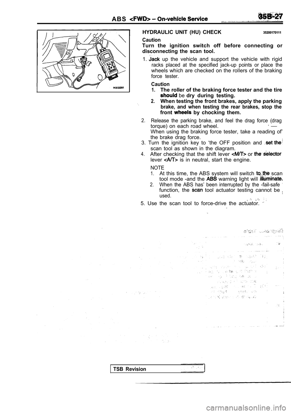
HYDRAULIC UNIT (HU) CHECK
Caution
35200170111
Turn the ignition switch off before connecting ordisconnecting the scan tool.
1.
up the vehicle and support the vehicle with rigid
racks placed at the specified jack-up points or pla ce the
wheels which are checked on the rollers of the brak ing
force tester.
Caution
1.The roller of the braking force tester and the tire
be dry during testing.
2.When testing the front brakes, apply the parking
brake, and when testing the rear brakes, stop the
front by chocking them.
2.Release the parking brake, and feel the drag force (drag
torque) on each road wheel.. __
When using the braking force tester, take a reading of’
the brake drag force.
3. Turn the ignition key to ‘the OFF position and
scan tool as shown in the diagram.
4.After checking that the shift lever or
lever is in neutral, start the engine.
NOTE
1.At this time, the ABS system will switch scan
tool mode -and the
warning light will
2.When the ABS has’ been interrupted by the -fail-saf e
function, the tool actuator testing cannot be
used.
5. Use the scan tool to force-drive the actuator.
TSB Revision
Page 1753 of 2103

Caution,
Turn the ignition switch off before
t h e
If the scan tool is disconnected while the ignition
switch
the diagnostic trouble codes will be memorized!
the warning’ light’ may
1. Jack up the vehicle and support: the vehicle with rigid;
racks at the specified jack-up place the
wheels which ‘are checked on. .therollers of the braking
force tester.
Caution
The roller of the braking force tester the
shouldbedry during
2. When parking!
the rear brakes, stop
them.,
2.Release the parking brake, and feel
torque) ‘each road wheel. .
using “the force tester, take “a
‘brake drag
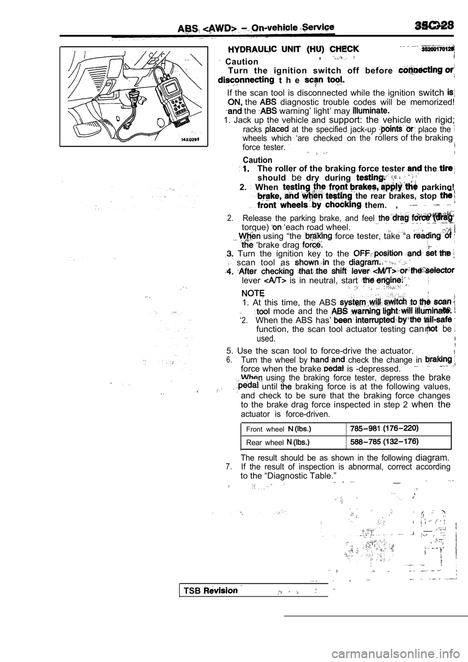
Turn the ignition key to the
scan tool as the
lever is in neutral, start
1. At this time, the ABS
‘2.
mode and the
When the ABS has’
function, the scan tool actuator testing canbe
used.
5. Use the scan tool to force-drive the actuator.
6.Turn the wheel by check the change in
force when the brake is -depressed.
using the braking force tester, depress the brake
until braking force is at the following values,
and check to be sure that the braking force changes
to the brake drag force inspected in step 2 when the
actuator is force-driven.
Front wheel
Rear wheel
The result should be as shown in the following diagram.
7.If the result of inspection is abnormal, correct ac cording
to the “Diagnostic Table.”__ .
,
__
TSB
Page 1775 of 2103

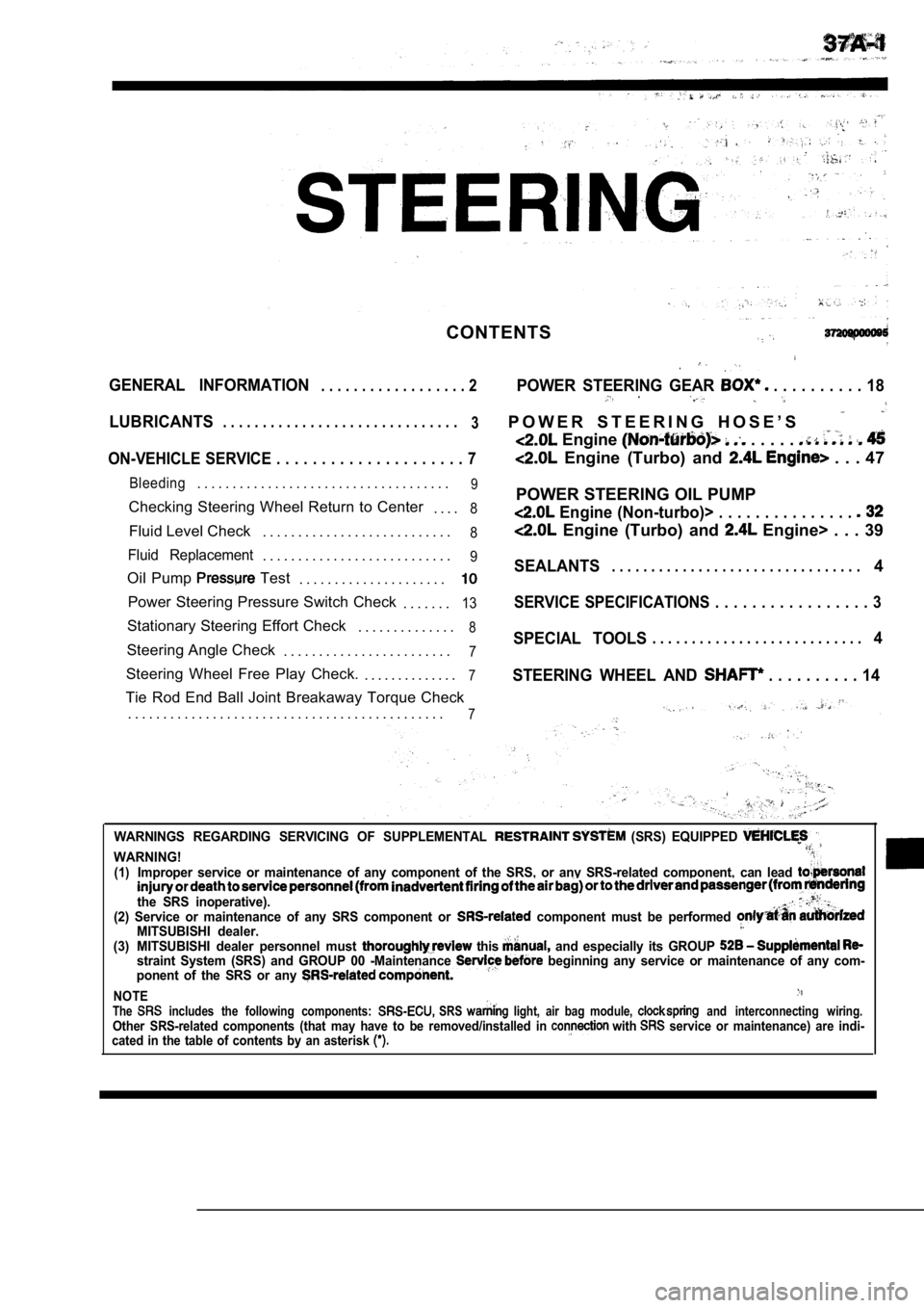
CONTENTS
GENERAL INFORMATION. . . . . . . . . . . . . . . . . . 2POWER STEERING GEAR . . . . . . . . . . 18
LUBRICANTS. . . . . . . . . . . . . . . . . . . . . . . . . . . . . .
3P O W E R S T E E R I N G H O S E ’ S
Engine . . . . .
ON-VEHICLE SERVICE . . . . . . . . . . . . . . . . . . . . . 7 Engine (Turbo) and . . . 47
Bleeding. . . . . . . . . . . . . . . . . . . . . . . . . . . . . . . . . . . .9
Checking Steering Wheel Return to Center
. . . .8
Fluid Level Check. . . . . . . . . . . . . . . . . . . . . . . . . . .8
Fluid Replacement. . . . . . . . . . . . . . . . . . . . . . . . . . .9
Oil Pump Test
. . . . . . . . . . . . . . . . . . . . .
Power Steering Pressure Switch Check
. . . . . . .13
Stationary Steering Effort Check. . . . . . . . . . . . . .8
Steering Angle Check. . . . . . . . . . . . . . . . . . . . . . . .7
Steering Wheel Free Play Check. . . . . . . . . . . . . . .7
Tie Rod End Ball Joint Breakaway Torque Check
. . . . . . . . . . . . . . . . . . . . . . . . . . . . . . . . . . . . . . . . . . . . .
7
POWER STEERING OIL PUMP
Engine (Non-turbo)> . . . . . . . . . . . . . . .
Engine (Turbo) and Engine> . . . 39
SEALANTS. . . . . . . . . . . . . . . . . . . . . . . . . . . . . . . .4
SERVICE SPECIFICATIONS . . . . . . . . . . . . . . . . . 3
SPECIAL TOOLS. . . . . . . . . . . . . . . . . . . . . . . . . . .4
STEERING WHEEL AND
. . . . . . . . . . 14
WARNINGS REGARDING SERVICING OF SUPPLEMENTAL (SRS) EQUIPPED
WARNING!(1)Improper service or maintenance of any component of the SRS, or any SRS-related component, can lead
the SRS inoperative).(2) Service or maintenance of any SRS component or component must be performed MITSUBISHI dealer.(3) MITSUBISHI dealer personnel must this and especially its GROUP straint System (SRS) and GROUP 00 -Maintenance beginning any service or maintenance of any com-
ponent of the SRS or any
NOTEThe includes the following components: SRS light, air bag module, and interconnecting wiring.Other SRS-related components (that may have to be r emoved/installed in with service or maintenance) are indi-
cated in the table of contents by an asterisk
Page 1777 of 2103

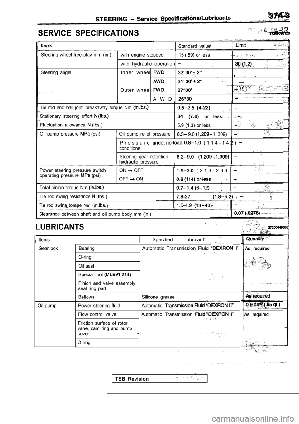
SERVICE SPECIFICATIONS
Standard value
Steering wheel free play mm (in.) with engine stopped15
or less,
with hydraulic operation
Steering angleInner wheel 2“
__
.
O u t e r w h e e l
A W D
Tie rod end ball joint breakaway torque Nm (4-22)
Stationary steering effort 34 (7.6) or less. .
Fluctuation allowance (Ibs.)
5.9 (1.3) or less
Oil pump relief pressureOil pump pressure (psi) 9.0 ,309)
P r e s s u r e ( 1 1 4 - 1 4 2 )
conditions
Steering gear retention
pressure
Power steering pressure switch
operating pressure
(psi)
Total pinion torque Nm
Tie rod swing resistance (Ibs.) ON
OFF
OFF
ON
( 2 1 3 - 2 8 4 )
7.8-27
rod swina toraueNm1.5-4.9
between shaft and oil pump body mm (in.)
LUBRICANTS
IItems
Bearing
O-ring
Oil seal
.
Specified lubricant’
Gear boxAutomatic Transmission Fluid II”
.As required
Oil pump Special tool
214)
Pinion and valve assembly
seal ring part
,
BellowsSilicone grease
Power steering fluid Automatic
Flow control valve Automatic Transmission II”
Friction surface of rotor
vane, cam ring and pump
cover.
O-ring
As required
TSB Revision
Page 1778 of 2103
SEALANTS
Sealants/Special Tools
.
I t e m s Specified sealant
Power
steering
gear box End plug screw ATD Part ‘No. or ‘equivalent
Power steering rack support cover screw
Dust cover lip for tie rod end ball joint
SPECIAL TOOLS
Tool
0
Tool number and name
or
Steering linkage puller
socket
Oil pressure gauge
assembly
548
Engine (Non-turbo)>
Power steering oil
gauge adapter
side)
Engine (Non-turbo)>
steering oil
gauge adapter
side)
or
Engine (Turbo)
Engine>
steering oil
gauge adapter
pump side)
Engine (Turbo)
Engine>
steering oil pressure adapter (hose side)
Generalservice tool
TSBRevision,
Application
Tie, rod knuckle
Tie rod end ball joint breakaway
torque check
Page 1779 of 2103
Special
Steering wheel puller
socket
Torque wrench socket
l support
120
Needle bearing puller
.
Tool not available roller bearing removal __
. .
197
Bar (long type) General service tool and oil seal
i n s t a l l a t i o n
Oil
199
Oil seal installerGeneral service tool
,
General service tool
Oil seal installer attach-
ment
General service tool Needle rotter bearing
Oil seal bearing installerinstallation -- B a l l b e a r i n g
TSB Revision