1990 MITSUBISHI SPYDER maintenance
[x] Cancel search: maintenancePage 51 of 2103
GENERAL Maintenance
a
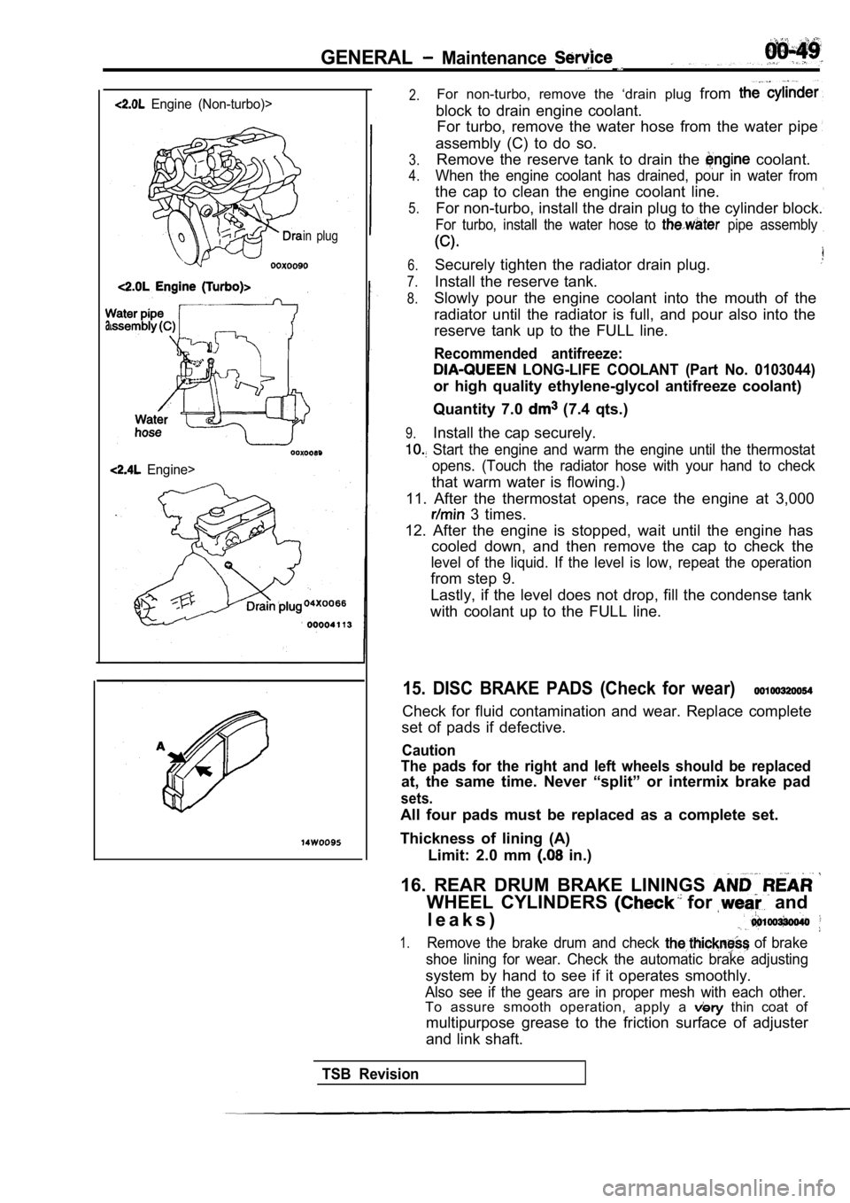
Engine (Non-turbo)>
in plug
Engine>
2.For non-turbo, remove the ‘drain plug from
block to drain engine coolant.
For turbo, remove the water hose from the water pip e
assembly (C) to do so.
3.
4.
5.Remove the reserve tank to drain the coolant.
When the engine coolant has drained, pour in water from
the cap to clean the engine coolant line.
For non-turbo, install the drain plug to the cylind er block.
For turbo, install the water hose to pipe assembly
6.
7.
8.
Securely tighten the radiator drain plug.
Install the reserve tank.
9.
Slowly pour the engine coolant into the mouth of th e
radiator until the radiator is full, and pour also into the
reserve tank up to the FULL line.
Recommended antifreeze:
LONG-LIFE COOLANT (Part No. 0103044)
or high quality ethylene-glycol antifreeze coolant)
Quantity 7.0
(7.4 qts.)
Install the cap securely.
Start the engine and warm the engine until the the rmostat
opens. (Touch the radiator hose with your hand to c heck
that warm water is flowing.)
11. After the thermostat opens, race the engine at 3,000
3 times.
12. After the engine is stopped, wait until the eng ine has
cooled down, and then remove the cap to check the
level of the liquid. If the level is low, repeat th e operation
from step 9.
Lastly, if the level does not drop, fill the conden se tank
with coolant up to the FULL line.
15. DISC BRAKE PADS (Check for wear)
Check for fluid contamination and wear. Replace com plete
set of pads if defective.
Caution
The pads for the right and left wheels should be re placed
at, the same time. Never “split” or intermix brake pad
sets.
All four pads must be replaced as a complete set.
Thickness of lining (A) Limit: 2.0 mm
in.)
16. REAR DRUM BRAKE LININGS
WHEEL CYLINDERS for and
l e a k s )
1.Remove the brake drum and check of brake
shoe lining for wear. Check the automatic brake adj usting
system by hand to see if it operates smoothly.
Also see if the gears are in proper mesh with each other.
To assure smooth operation, apply a thin coat of
multipurpose grease to the friction surface of adju ster
and link shaft.
TSB Revision
Page 52 of 2103

GENERAL Maintenance Service
2.Check the wheel cylinder boots for evidence, a’ brake
fluid leak. Visually check the
boots for tears or
cracks. (A slight amount of fluid on the boot may not
be a leak, but may be preservative assembly.)
Caution
The shoes for the right and left be,
replaced at the same time.
Never split or intermix brake
sets.
All four shoes must be replaced as a set.
Thickness of lining
Limit: 1.0 mm in.)
17. BRAKE HOSES (Check for
leaks)
Check of brake hoses and tubing should be
brake service operations.
The hoses should be checked for:
1.Correct length, severe surface cracking, pulling, scuffing
or worn spots. (If the fabric casing of the hoses i s exposed
by cracks of abrasion in the rubber hose cover, the hoses
should be replaced. Eventual deterioration of may
occur with possible bursting failure.)
2. Faulty installation, casing twisting or interfer ence
wheel,’ tire or chassis.
18. BALL JOINT AND STEERING SEALS
(Check for grease leaks damage)
1. These components, which are permanently lubricat ed
at the factory, do not require periodic lubrication. Damaged
seals and boots should be replaced to prevent leakage
or contamination of the grease.
2.Check the dust cover and boots for proper sealing, leakage
and damage. Replace them if defective.
19. DRIVE SHAFT BOOTS (Check for leaks
and damage)
1. These components, which are permanently lubricat ed
at the factory, do not require periodic Damaged
boots should be replaced to prevent leakage or contamina-
tion of the grease.
2.Check the boots for proper sealing, leakage and damage.
Replace it if defective.
AXLE OIL (Check oil level)-AWD
Remove the filler plug and check the oil level at bottom of
filler hole. If the oil level is slightly below the filler hole, it
is in satisfactory condition.
Page 53 of 2103
GENERAL Maintenance
21 SYSTEM component
damage, to wiring,
harness, etc.)
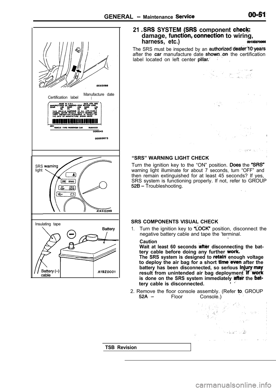
Certification labelManufacture dateI
SRSlight
Insulating tape
The SRS must be inspected by an
after the manufacture date the certification
label located on left center
,
“SRS” WARNING LIGHT CHECK,
Turn the ignition key to the “ON” position. the
warning light illuminate for about 7 seconds, turn “OFF” and
then remain extinguished for at least 45 seconds? I f yes,
SRS system is functioning properly. If not, refer t o GROUP
Troubleshooting.
SRS COMPONENTS VISUAL CHECK
1.Turn the ignition key to position, disconnect the
negative battery cable and tape the ‘terminal.
Caution
Wait at least 60 seconds
disconnecting the bat-
tery cable before doing any further
The SRS system is designed to enough voltage
to deploy the air bag for a short after the
battery has been disconnected, so serlous
result from unintended air bag deployment
is done on the SRS system immediately the
tery cable is disconnected. ,
2. Remove the floor console assembly. (Refer GROUP
Floor Console.)
TSB Revision
Page 54 of 2103
GENERAL Maintenance Service
0 0 0 0 0 1 6 7
Inflator case
CHECK
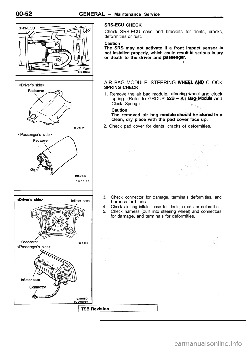
Check SRS-ECU case and brackets for dents, cracks,
deformities or rust.
Caution
The SRS may not activate if a front impact sensor
not installed properly, which could result serious injury
or death to the driver and ,
AIR BAG MODULE, STEERING
CLOCK
SPRING CHECK
1. Remove the air bag module,
and clock
spring. (Refer to GROUP
and
Clock Spring.)
Caution
The removed air bag be In a
clean, dry place with the pad cover face up.
2. Check pad cover for dents, cracks of deformities .
3.Check connector for damage, terminals deformities, and
harness for binds.
4.Check air bag inflator case for dents, cracks or deformities.
5.Check harness (built into steering wheel) and conne ctors
for damage, and terminals for deformities.
Page 55 of 2103
G E N E R A L Maintenance
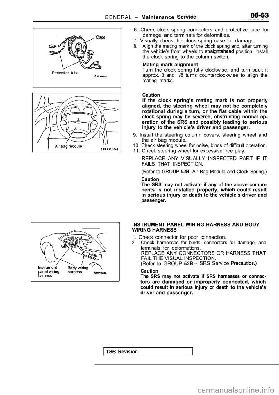
Protective tube
harness
6. Check clock spring connectors and protective tube for
damage, and terminals for deformities.
7. Visually check the clock spring case for damage.
8.Align the mating mark of the clock spring and, afte r turning
the vehicle’s front wheels to
position, install
the clock spring to the column switch.
Mating mark alignment
Turn the clock spring fully clockwise, and turn bac k it
approx. 3 and
turns counterclockwise to align the
mating marks.
Caution
If the clock spring’s mating mark is not properly
aligned, the steering wheel may not be completely
rotational during a turn, or the flat cable within the
clock spring may be severed, obstructing normal op-
eration of the SRS and possibly leading to serious
injury to the vehicle’s driver and passenger.
9. Install the steering column covers, steering whe el and
the air bag module.
10. Check steering wheel for noise, binds of diffic ult operation.
11. Check steering wheel for excessive free play.
REPLACE ANY VISUALLY INSPECTED PART IF IT
FAILS THAT INSPECTION.
(Refer to GROUP
-Air Bag Module and Clock Spring.)
Caution
The SRS may not activate if any of the above compo-
nents is not installed properly, could result
in serious injury or death to the vehicle’s driver and
passenger.
INSTRUMENT PANEL WIRING HARNESS AND BODY
WIRING HARNESS
1. Check connector for poor connection.
2.Check harnesses for binds, connectors for damage, a nd
terminals for deformations.
REPLACE ANY CONNECTORS OR HARNESS THAT
FAIL THE VISUAL INSPECTION.
(Refer to GROUP
SRS Service
Caution
The SRS may not activate if SRS harnesses or connec -
tors are damaged or improperly connected, which
could result in serious injury or death to the vehicle’s
driver and passenger.
Revision
Page 56 of 2103
GENERAL Maintenance Service;
Revision
22. EXHAUST SYSTEM (CONNECTION
OF MUFFLER, PIPINGS AND, CONVERTER
HEAT SHIELDS) (Check
as’
required)
1.Check for holes and gas leaks’dwe to damage;
etc.
2.Check the joints and connections for looseness and gas’
leaks.
3. Check the hanger rubber and brackets for damage.
Page 76 of 2103
ENGINE Engine
ENGINE ASSEMBLY
REMOVAL AND INSTALLATION
Operationl Fuel Line Pressure Releasing(Refer to GROUP On-vehicle Service.)l ‘Hood Removall Engine Coolant DrainingRefer to GROUP 00 Maintenance Service.)l Assembly Removal Refer to GROUP TransaxleA Refer to GROUP Transaxle
Refer to GROUP Transaxle
Refer to GROUP TransaxleAssembly.)lRadiator Removal (Refer to GROUP 14 Radiator.)l Under Cover Removal (Refer to GROUP 42 Under Cover.)
6
2216
Operationl Radiator Installation(Refer to GROUP 14 Radiator.)l Transaxle Assembly Removal Refer to GROUP Assembly.) Refer to GROUP Transaxle
Refer to GROUP Transaxle
Refer to GROUP
Transaxle
l Engineoolant(Refer to GROUP 00 l Hoodl Accelerator Cable Adjustment(Refer to GROUP 17 l Under Cover Installation(Refer to GROUP 42 Under l Drive Belt Adjustment
34
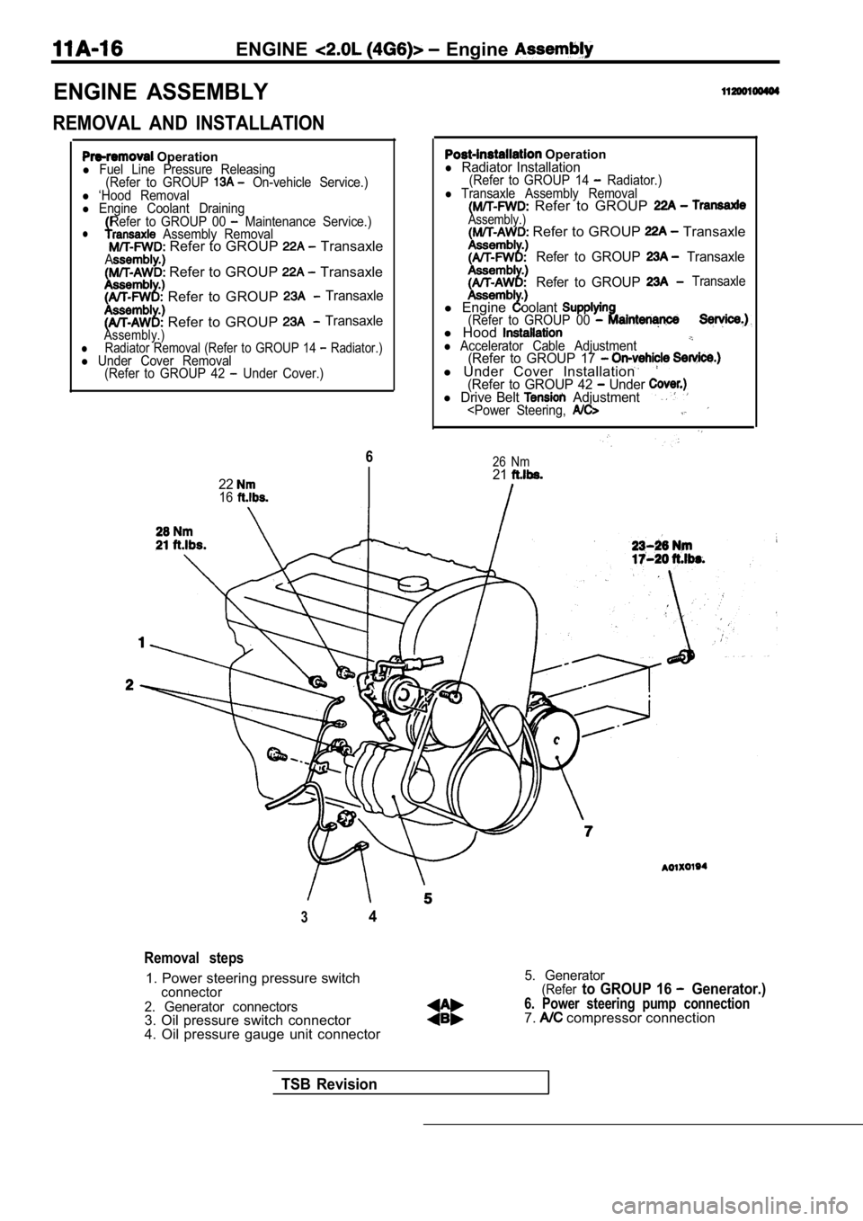
Removal steps
1. Power steering pressure switchconnector
2. Generator connectors
3. Oil pressure switch connector
4. Oil pressure gauge unit connector
5. Generator(Referto GROUP 16 Generator.)
6. Power steering pump connection7. compressor connection
TSB Revision
Page 91 of 2103
ENGINE Cylinder Head
CYLINDER HEAD GASKET
REMOVAL AND INSTALLATION
Pre-removal Operationl Fuel Line Inner Pressure Release(Refer to GROUP On-vehiclel Engine Coolant Draining(Refer to GROUP 00 Maintenance Service.)l Engine Oil Draining(Refer to GROUP 00 Maintenance Service.)
3.62.9 Nm
2.2
4.9 Nm
220 1
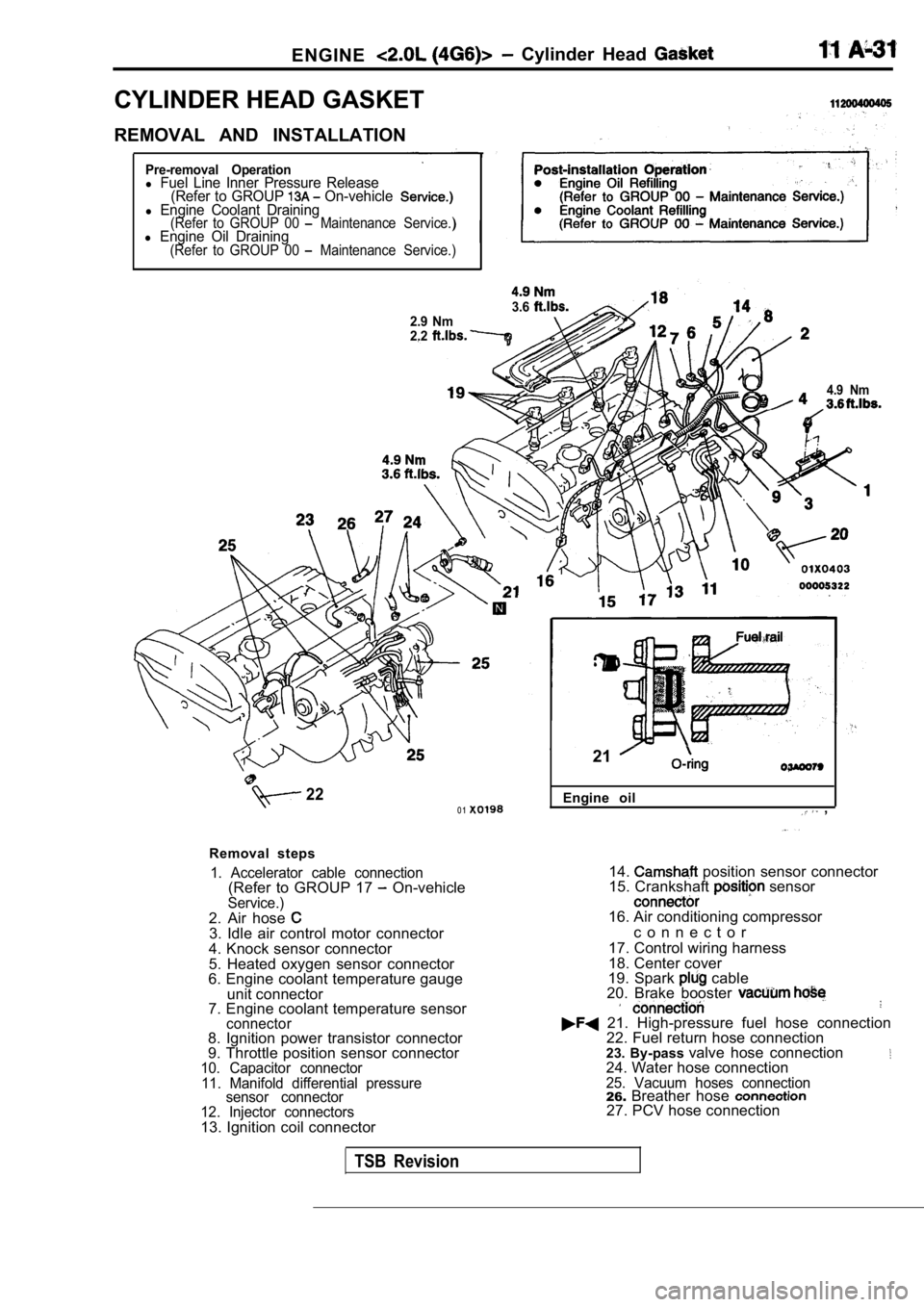
Removal steps
1. Accelerator cable connection(Refer to GROUP 17 On-vehicleService.)2. Air hose 3. Idle air control motor connector
4. Knock sensor connector
5. Heated oxygen sensor connector
6. Engine coolant temperature gauge
unit connector
7. Engine coolant temperature sensor
connector8. Ignition power transistor connector
9. Throttle position sensor connector
10. Capacitor connector
11. Manifold differential pressure sensor connector
12. Injector connectors
13. Ignition coil connector Engine oil
,
21
14. position sensor connector
15. Crankshaft sensor
16. Air conditioning compressor
c o n n e c t o r
17. Control wiring harness
18. Center cover
19. Spark
cable
20. Brake booster
21. High-pressure fuel hose connection 22. Fuel return hose connection
23. By-pass valve hose connection
24. Water hose connection25. Vacuum hoses connection26.Breather hose 27. PCV hose connection
TSB Revision