Page 574 of 2103
![MITSUBISHI SPYDER 1990 Service Repair Manual E N G I N E
A N D ,
Code No. Differential
Malfunction
[Comment]BackgroundManifold differential se.
l pressure in the intake manifold. o r l o o s e Engine control. lThe engine co MITSUBISHI SPYDER 1990 Service Repair Manual E N G I N E
A N D ,
Code No. Differential
Malfunction
[Comment]BackgroundManifold differential se.
l pressure in the intake manifold. o r l o o s e Engine control. lThe engine co](/manual-img/19/57345/w960_57345-573.png)
E N G I N E
A N D ,
Code No. Differential
Malfunction
[Comment]BackgroundManifold differential se.
l pressure in the intake manifold. o r l o o s e Engine control. lThe engine control module checks whether the voltage output by manifold differential sure sensor is within a specified range.
Check Area, Judgement Criteria.
1. Check Areal min or more have passed after the engine was start ed.[However, this is only when the engine coolant temperature is or lower
when the engine is started.]
Engine coolant temperature is not lower than Intake air temperature is not lower than Barometric pressure is 76 (11 psi.) or higher. Volumetric efficiency is 30% 55%.
Judgement Criteria . ,
Sensor output voltage has continued to be not lowe
r than [corresponding toan absolute pressure of 118 (17 psi) or higher] for 4 sec.orSensoroutput voltage has continued to be not higher than 0.1 [corresponding to ---
an absolute pressure of 2.4 (0.3 psi) or lower] for 4 sec.
2. Check Area
8 min or more have passed engine Started.
[However, this is only when the engine coolant or lower when the engine is Engine coolant temperature is not lower than Intake air temperature is not lower than Barometric pressure is 76 (11 psi.) or higher. Volumetric efficiency is 30% or lower.
Judgement Criteria ,
l Sensor output voltage is 4.2 or higher for 4 seconds [absolute pressure is 108 (16 psi.) or more]
Check Area 8 min or more have passed after the engine was sta rted.
,
.
. , ,
[However, this is only when the engine coolant temperature is or lowerwhen engine is started.]
l Engine coolant temperature is not lower than .l Intake air temperature is not lower than l Barometric pressure is 76 (11 psi.) or higher. Volumetric efficiency is 70% or higher.
Judgement Criterial Sensor output voltage is or lower for 4 seconds [absolute pressure is 46 (6.7 psi.) or less]I
TSB Revision.
Page 628 of 2103

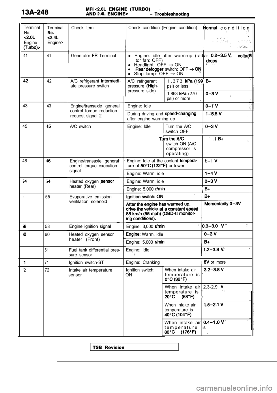
ENGINE (TURBO)
AND ENGINE> Troubleshooting
TerminalCheck itemCheck condition (Engine condition) c o n d i t i o n
No.
Engine>
Terminal
No.
Engine
41 41Generator Terminall Engine: idle after warm-up (radia-
tor fan: OFF)
l Headlight: OFF ONl switch: OFF l Stop lamp: OFF ON
A/C refrigerant A/C refrigerant1 , 3 7 3
ate pressure switch
pressurepsi) or less
pressure side)
1,863 (270
psi) or more
Engine/transaxle general
control torque reduction
request signal 2 Engine: Idle
During driving and
after engine warming up
Engine: Idle
Turn the A/C
,
switch OFF
switch ON (A/C
compressor is
operating)
Engine: Idle at the coolant b - l
ture of or lower
Engine: Warm, idle
Engine: Warm, idle
Engine: 5,000
the at a constant speed
Engine: 3,000
Warm, idle
Engine: 5,000
Engine: Idle
I
Engine: CrankingIor more
Ignition switch:
ON When intake air
t e m p e r a t u r e i s
When intake air 2.3-2.9
t e m p e r a t u r e i s
When intake air
temperature is
When intake air
t e m p e r a t u r e i s
.
42
4343
A/C switch45
46Engine/transaxle general
control torque execution
signal
Heated oxygen
heater (Rear)
55Evaporative emission
ventilation solenoid
58Engine ignition signal
Heated oxygen sensor
heater (Front)
60
61Fuel tank differential pres-
sure sensor
71Ignition switch-ST
Intake air temperature
sensor
‘272
TSB Revision
Page 629 of 2103

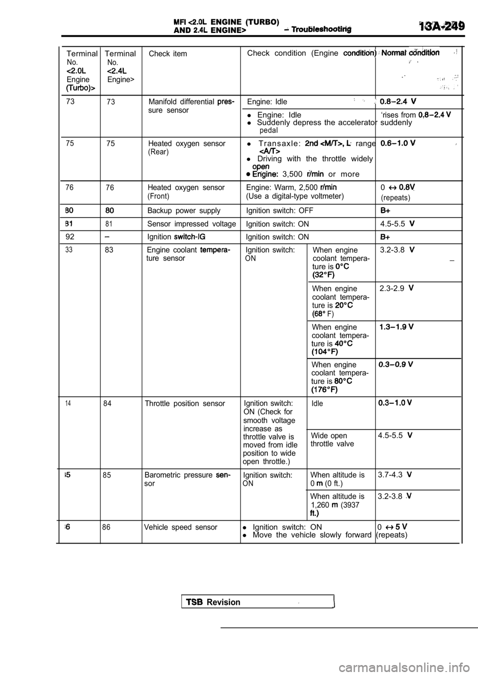
ENGINE (TURBO)
AND
ENGINE>
Terminal TerminalCheck itemCheck condition (Engine
No. No.
Engine Engine>
7373Manifold differential Engine: Idle
sure sensorl Engine: Idle‘rises from l Suddenly depress the accelerator suddenlypedal
75
75 Heated oxygen sensorl T r a n s a x l e : range
(Rear)l Driving with the throttle widely
3,500 or more
76
76Heated oxygen sensor Engine: Warm, 2,500 0
(Front)(Use a digital-type voltmeter)(repeats)
Backup power supply Ignition switch: OFF
81Sensor impressed voltage Ignition switch: ON4.5-5.5
92IgnitionIgnition switch: ON
3383 Engine coolant Ignition switch:When engine3.2-3.8
ture sensorONcoolant tempera-_
ture is
When engine2.3-2.9
coolant tempera-
ture is
F)
When engine
coolant tempera-
ture is
When engine
coolant tempera-
ture is
1484Throttle position sensor Ignition switch:Idle
ON (Check for
smooth voltage increase as
throttle valve is Wide open
4.5-5.5
moved from idlethrottle valve
position to wide
open throttle.)
85Barometric pressure Ignition switch: When altitude is3.7-4.3
sorON0 (0 ft.)
When altitude is
3.2-3.8
1,260 (3937
86Vehicle speed sensorl Ignition switch: ON 0l Move the vehicle slowly forward (repeats)
Revision
Page 652 of 2103
COMPONENT LOCATION
Engine (Turbo)>
Name
Air conditioning compressor clutch relay
Air conditioning switch Camshaft position sensor
Check engine/Malfunction indicator lamp
Crankshaft position sensor Data link connector
EGR solenoid
Engine control module (ECM)
Engine coolant temperature sensor
Evaporative emission purge solenoid
Fuel pressure solenoid
Fuel pump check terminal
Fuel pump relay
Heated oxygen sensor (Front)
Heated oxygen sensor (Rear)
Idle air control motor Ignition coil (Ignition power transistor)
NOTESymbol NameSymbol
A Injector
Knock sensor
Manifold differential pressure (MDP) sensor
fuel injection (MFI) relay
Park/Neutral position switch
Power steering pressure switch
ResistorI.
Throttle position sensor (with
throttle position switch)
Turbocharger waste gate solenoid
Vehicle speed sensor
Volume air flow sensor (with air
temperature sensor and barometric pressure
sensor)
.
The “Name” column is in alphabetical order.
Page 656 of 2103
Name
Air conditioning compressor clutch relay
Air conditioning switchSymbol Name
air control motor
coil power transistor)
Camshaft position sensor
Check engine/Malfunction indicator lamp
Crankshaft position sensor
Data link connectorIgnition power transistor
injector
Manifold differential pressure sensor
EGR solenoid fuel relavI I
Engine control module (ECM)
Engine coolant temperature sensorPark/Neutral position switch
Power steering pressure switch
Evaporative emission purge solenoid
Fuel
check terminal
Throttle position sensor (with
throttle position switch)
Fuel pump relay
Fuel pump relay module
Heated oxygen sensor (Front)
Heated oxygen sensor (Rear)Vehicle speed sensor.
Vehicle speed sensor
Volume air flow sensor (with
temperature sensor and barometric pressure
sensor)
NOTE
The “Name” column is in alphabetical order.
Page 678 of 2103
FUEL SUPPLY Fuel Tank
13500010032
(1) The fuel tank is located under the floor of the The fuel tank AWD from a high
rear seats to provide increased safety. density: pol yethylene
material and
(2)A fuel cut-off valve has been’adopted to preventblow-formed an ‘tank.
fuel from leaking out in the event of a collision.
Specifications
Fuel tank capacity (gals.)
Fuel pump type64 (16.9)
Electrical, in-tank type
ItemsStandard value.
Fuel tank differential pressure sensor output volta ge 2.0 3.0 ,
Test harness set pressure sensor
TSB Revision
Page 682 of 2103
Engine>FUEL SUPPLY
Fuel
(Refer to GROUP On-vehicle Service.)
2.5Nm1.8
25 Nm
Removal steps
1.Fuel tank2. Vapor hose
3. High-pressure fuel hose
4. Return hose
5. Fuel tank differential pressuresensor6. Fuel pump assembly
7. Fuel gauge unit
8. Fuel cut-off valve assembly 9. Vapor hose
lo. Fuel tank filler cap
11. Filler hose
1
13. Fuel tank filler tube protector14. Reinforcement 15. tank tube assembly16. Packing
When replacing pump fuel gauge
unit only, it is possible to work from the service holes
underneath the rear seat, without having toremove the fuel tank. (Refer
TSB Revision
Page 684 of 2103
FUEL SUPPLY Fuel Tank
Fuel gauge unit and
pipe assembly
Front of
Mating marks
Fuel gauge unit and
pump assembly
Mating marks
INSTALLATION SERVICE POINT
INSTALLATION ,
Use the special tool to tighten the the
so that the marks on the fuel tank the, unit
and pump assembly (or the fuel gauge and pipe assembly)
are aligned.
Caution
Make sure that the fuel gauge unit and pump assembl y
(or the fuel gauge unit and pipe assembly) does not turn
together with the cap when tightening the cap.
If the mating marks are not aligned, the position o f the
float will not be correct and the fuel gauge indicator light
and the fuel level gauge will properly.
FUEL TANK DIFFERENTIAL PRESSURE SENSOR
INSTALLATION
Caution
When removing or installing the sensor, take care n ot
to damage sealing.
TSB Revision