1990 MITSUBISHI SPYDER oil type
[x] Cancel search: oil typePage 214 of 2103
ENGINE OVERHAUL
FORM-IN-PLACE GASKETS
There are numerous places where form-in-place gaskets are used on the engine. Care must be
when applying form-in-place gaskets to assure obtaining the desired results. size, continuity, ‘and
location are of great importance. Too thin a bead can result in leakage
too much can result’ in
spill-over which can break off and obstruct fluid f eed lines.
A continuous bead of the proper width
essential to obtain a leak-free joint.
GASKET DISASSEMBLY
Parts assembled with form-in-place gaskets may be d isassembled without unusual effort’
it may be necessary to lightly tap the part with a mallet or other suitable tool to break the seal between
the mating surfaces.A flat gasket scraper may also be lightly tapped in to the joint but care be
taken not to damage the mating surfaces.
SURFACE PREPARATION
Scrape clean or wire brush all gasketsurfaces removing all loose material. Inspect
assure gasket rails are flat.
Flatten rails with a hammer on a flat plate if
must be free of oil and dirt. Make sure old gasket material is removed from blind
FORM-IN-PLACE GASKET APPLICATION
Assembling parts using a form-in-place gasket requires care but it’s easier than using precut gaskets.
Gasket material should be applied sparingly 1 mm
inch.) diameter or less to one
surface, Be certain the material surrounds each mou nting hole.
Excess material can easily be
‘off. Components should be torqued in place within 15 minutes. The use of a locating dowel is recommen ded
during assembly, to prevent smearing the material off location.
Loctite 18718 gasket material or equivalent should be applied in a continuous bead
3
mm
inch.) in diameter. All mounting holes must be circled.
For corner sealing, 3.17 or 6.35
mm
or inch.) drop is placed in the center of the gasket contact area. Uncured may
be removed with a shop towels. Components should be torqued in place while the sea lant
wet
to the touch (within 10 minutes). The usage of a locating dowel is recommended during assembly to
prevent smearing of material off location.
MOPAR TORQUE CURE GASKET MAKER
Mopar torque cure gasket maker is a unique anaerobi c type gasket material to be used ONLY
the and engine block. The material cures in the absenc e of air when. two
metallic surfaces. It will not cure if left in the uncovered tube. This anaerobic material
specially made
to seal the area between the
and cylinder block without disturbing the bearing’ or
alignment of these components.. .
TSB Revision
Page 374 of 2103
ENGINE LUBRICATION General Information/Lubricants
G E N E R A L I N F O R M A T I O N
The lubrication method is a fully force-fed, full-f low
filtration type.
ENGINE OILS
Health Warning
Prolonged and repeated contact with mineral oil
will result in the removal of natural fats from the
skin, leading to dryness, irritation and dermatitis .
In addition, used engine oil
potentially
Recommended Precautions
The most effective precaution is to adapt working
practices which prevent, as far as practicable, the
risk of skin contact with mineral oils, for example
by using enclosed systems for handling used engine
oil and by degreasing components, where
practicable, before handling them.
Other precautions:
lAvoid prolonged and repeated contact with oils,
particularly used engine oils.
l Wear protective clothing, including impervious
gloves where practicable.
l Avoid contaminating clothes, particularly
underpants, with oil.
l Do not put oily rags in packets, the use of
overalls without pockets will avoid this.
l Do not wear heavily soiled clothing and
oil-impregnated foot-wear. Overalls must be
cleaned regularly and kept separate from
personal clothing.
LUBRICANTS
harmful contaminants which may cause skin cancer.
Adequate means of skin protection and washing
facilities must
provided.
Where there is a risk of eye contact, eye protection should be worn, for example,
chemical goggles or face shields; in addition
an eye wash facility should be provided.
Obtain First Aid treatment immediately for open
cuts and wounds.
Wash regularly with soap and water to ensure
all oil is removed, especially before
cleansers and nail brushes will help). After
cleaning, the application of
containing lanolin to replace the natural
oil is advised.. .
Do not use gasoline, kerosine, diesel fuel,
oil, thinners or solvents for cleaning skin.
Use barrier creams, applying them before each
work period, to help the removal of oil from
the skin after work.
If skin disorders develop, obtain medical advice
without delay.
Items Engine oil (API classification) Quantity (qts.)
Oil filter Engine (Non-turbo)
Engine (Turbo) and
Engine
Oil cooler
Engine (Turbo)>
Total quantity
Engine (Non-turbo)
and
Engine SH or higher
0.5
0.3
0.1
4.3 (4.5)
IIIII
Engine (Turbo) 4.4 (4.6)I
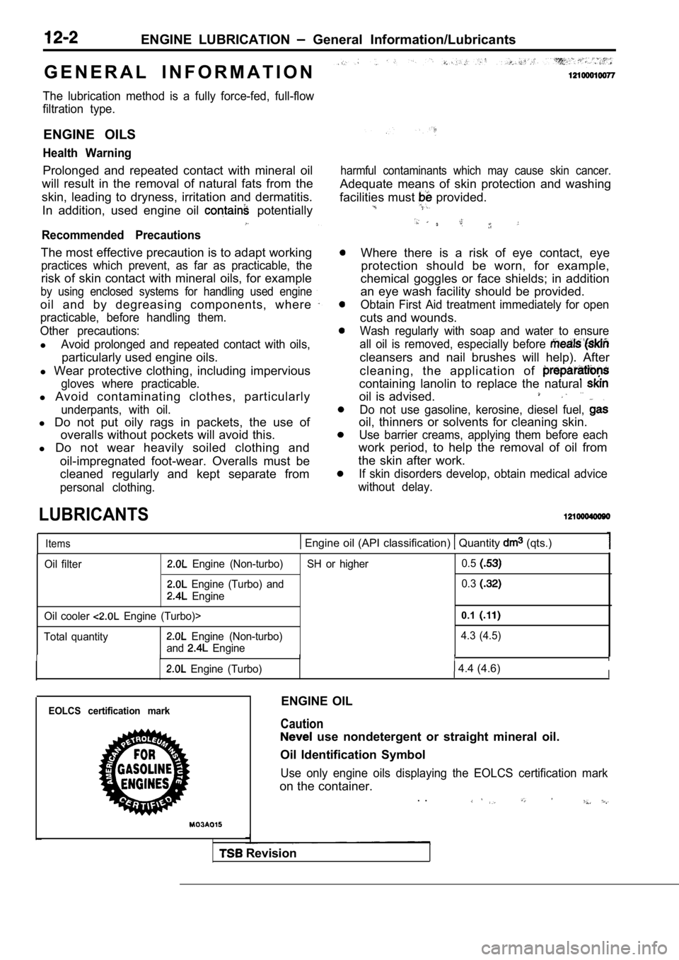
EOLCS certification markENGINE OIL
Caution
use nondetergent or straight mineral oil.
Oil Identification Symbol
Use only engine oils displaying the EOLCS certifica tion mark
on the container.
. .
Revision
Page 608 of 2103
ENGINE (TURBO)
AND ENGINE> Troubleshooting
INSPECTION PROCEDURE 37 ,
Ignition system: Inspection when no initial occurs,
Engine (Turbo)> NGMeasure at the ignition coil connector Check ignition circuit system.
l Connect the connector. (Use the test harness:
(Refer to INSPECTION PROCEDURE 34.)
lTo inspect, connect the primary voltage detection-typetachometer to the terminal 1 (red clip) and terminal 2
(black clip).
OK: Each terminal displays a speed on the engine tachometer that is
of the cranking speed.
OK
Engine>
Measure at the ignition coil connectors
l Connect the connector.
(Use the test harness:
lTo inspect, connect the primary voltage detection-t ypetachometer to the terminal 2.OK: Each terminal displays a speed on the engine
tachometer that is of the cranking speed.
OK
NGCheck the ignition circuit system.(Refer to INSPECTION PROCEDURE 34.)
OK:
NG Check that the crankshaft position sensor are properly installed.
INSPECTION PROCEDURE 38
Scan tool: Inspection when incomplete combustion oc curs.
YESINSPECTION CHART FOR DIAGNOSTIC Arediagnostic trouble code output (Refer to
SCAN TOOL Actuator te
07 Fuel pump (Refer toNG, Check the fuel pump system Engine (Turbo)>.(Refer to INSPECTION PROCEDURE 28.)Check the fuel pump system Engine>. (Refer-to IN-
SPECTION PROCEDURE 29.)
./I,’
SCAN TOOL Date list21(Refer to INSPECTION PROCEDURE TROUBLE CODE
NGSCAN TOOL Data Check the ignition switch-ST 18 Ignition switch-ST (Refer to (Refer to INSPECTION PROCEDURE 30.)
Check the ignition switch-ST andpark/neutralswitch
INSPECTION PROCEDURE 39 ,
when huntina occurs.
Clean the throttle body. (Refer to
I
Check and adiust the fixed SAS (Refer to
Check trouble symptom.
NG
Inspect air into the air intake system for vacuum l eaks.
l Broken intake manifold gasket
Broken air intake hose
l Broken vacuum hose
Page 692 of 2103
14-2ENGINE COOLING General Information
GENERAL INFORMATION , ,
The cooling system is designed to keep every partthat the heat absorbed by the coolant may be of the engine at appropriate temperature in diated into the air.
er condition the engine may be operated.
The cooling of the water-cooled, pressureThe water pump is of the centrifugal type and is
driven by the
the
forced circulation type in which the water pump crankshaft. .
pressurizes coolant and circulates it throughout th e
engine: If the coolant temperature exceeds the
scribed temperature, the thermostat opens to circu-
late the coolant through the radiator as well so
and is cooled the
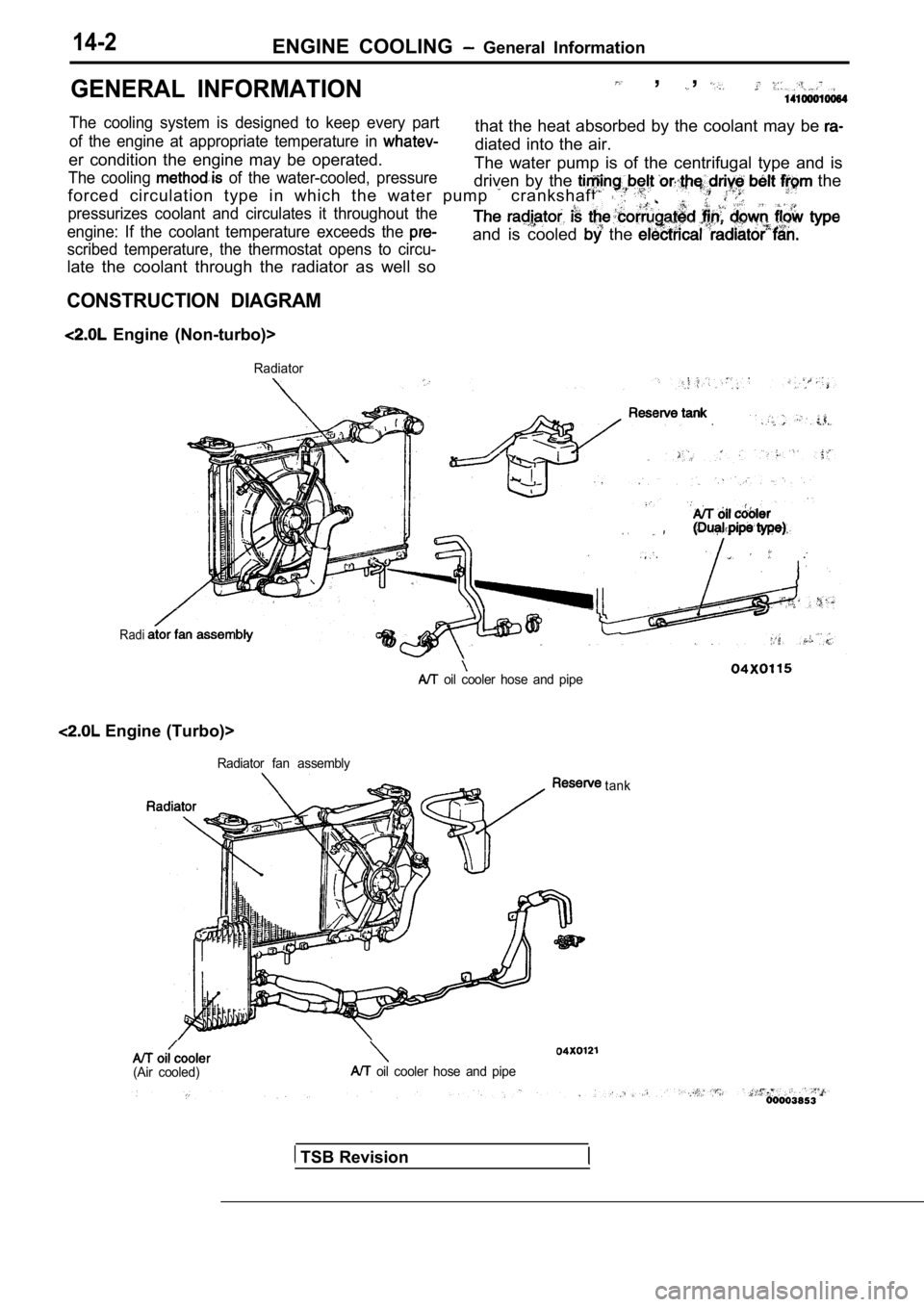
CONSTRUCTION DIAGRAM
Engine (Non-turbo)>
Radiator
Radi
.
oil cooler hose and pipe
Engine (Turbo)>
Radiator fan assembly
(Air cooled) oil cooler hose and pipetank
TSB Revision
Page 848 of 2103
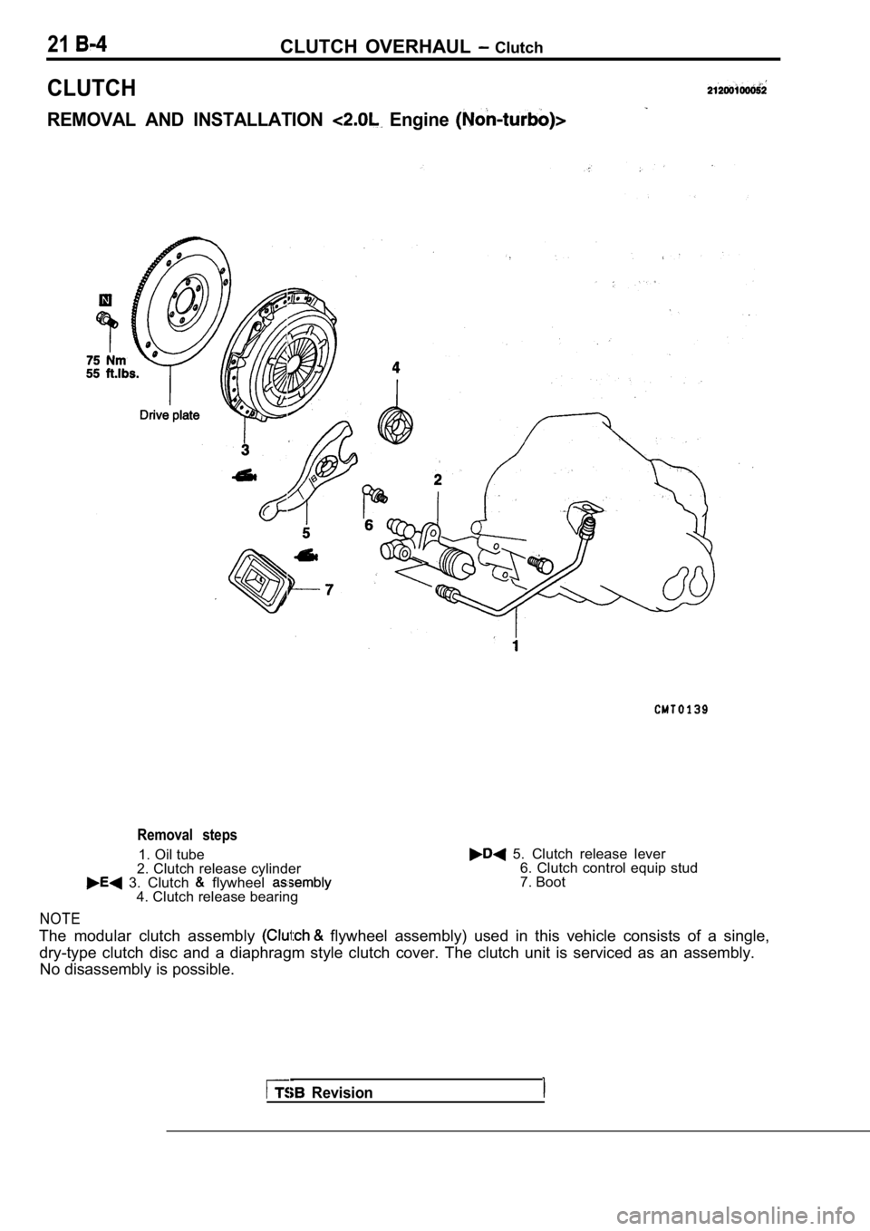
21CLUTCH OVERHAUL Clutch
CLUTCH
REMOVAL AND INSTALLATION Engine
Removal steps
1. Oil tube
2. Clutch release cylinder 5. Clutch release lever
3. Clutch flywheel
6. Clutch control equip stud
7. Boot
4. Clutch release bearing
NOTE
The modular clutch assembly flywheel assembly) used in this vehicle consists o f a single,
dry-type clutch disc and a diaphragm style clutch c over. The clutch unit is serviced as an assembly.
No disassembly is possible.
Revision
Page 1073 of 2103
AUTOMATIC TRANSAXLE
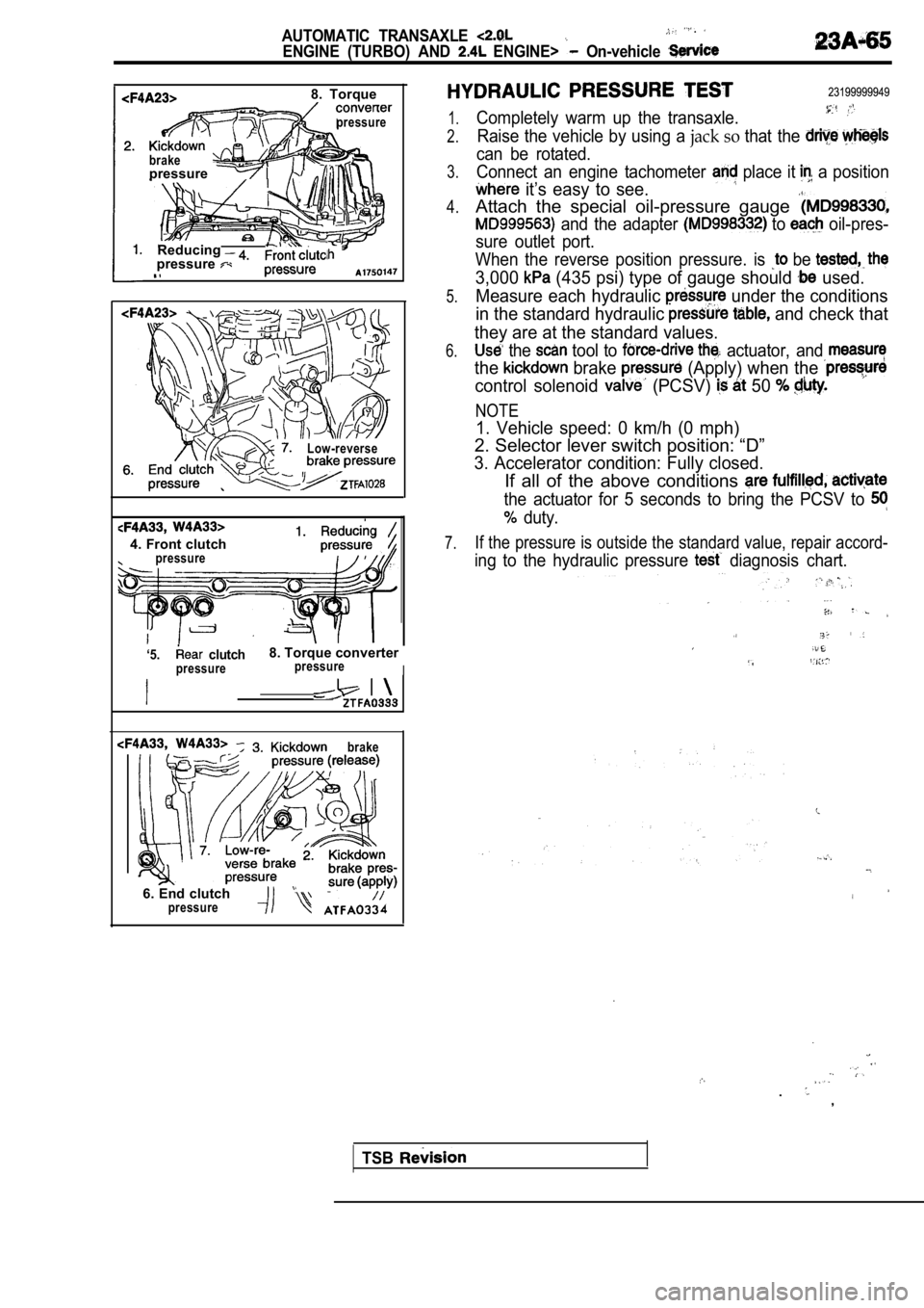
ENGINE (TURBO) AND ENGINE> On-vehicle
8. Torque
pressure
brakepressure
Reducingpressure
Low-reverse
4. Front clutchpressure
‘5. clutch8. Torque converter
pressurepressureI
brake
6. End clutch
23199999949
1.
2.
3.
4.
5.
6.
7.
Completely warm up the transaxle.
Raise the vehicle by using a jack so that the
can be rotated.
Connect an engine tachometer
place it a position
it’s easy to see.
Attach the special oil-pressure gauge
and the adapter to oil-pres-
sure outlet port.
When the reverse position pressure. is
be
3,000 (435 psi) type of gauge should used.
Measure each hydraulic
under the conditions
in the standard hydraulic
and check that
they are at the standard values.
the tool to actuator, and
the brake (Apply) when the
control solenoid (PCSV) 50
NOTE
1. Vehicle speed: 0 km/h (0 mph)
2. Selector lever switch position: “D”
3. Accelerator condition: Fully closed.
If all of the above conditions
the actuator for 5 seconds to bring the PCSV to
duty.
If the pressure is outside the standard value, repa ir accord-
ing to the hydraulic pressure diagnosis chart.
.
.
,
pressure
TSB
Page 1535 of 2103
R E A R A X L E
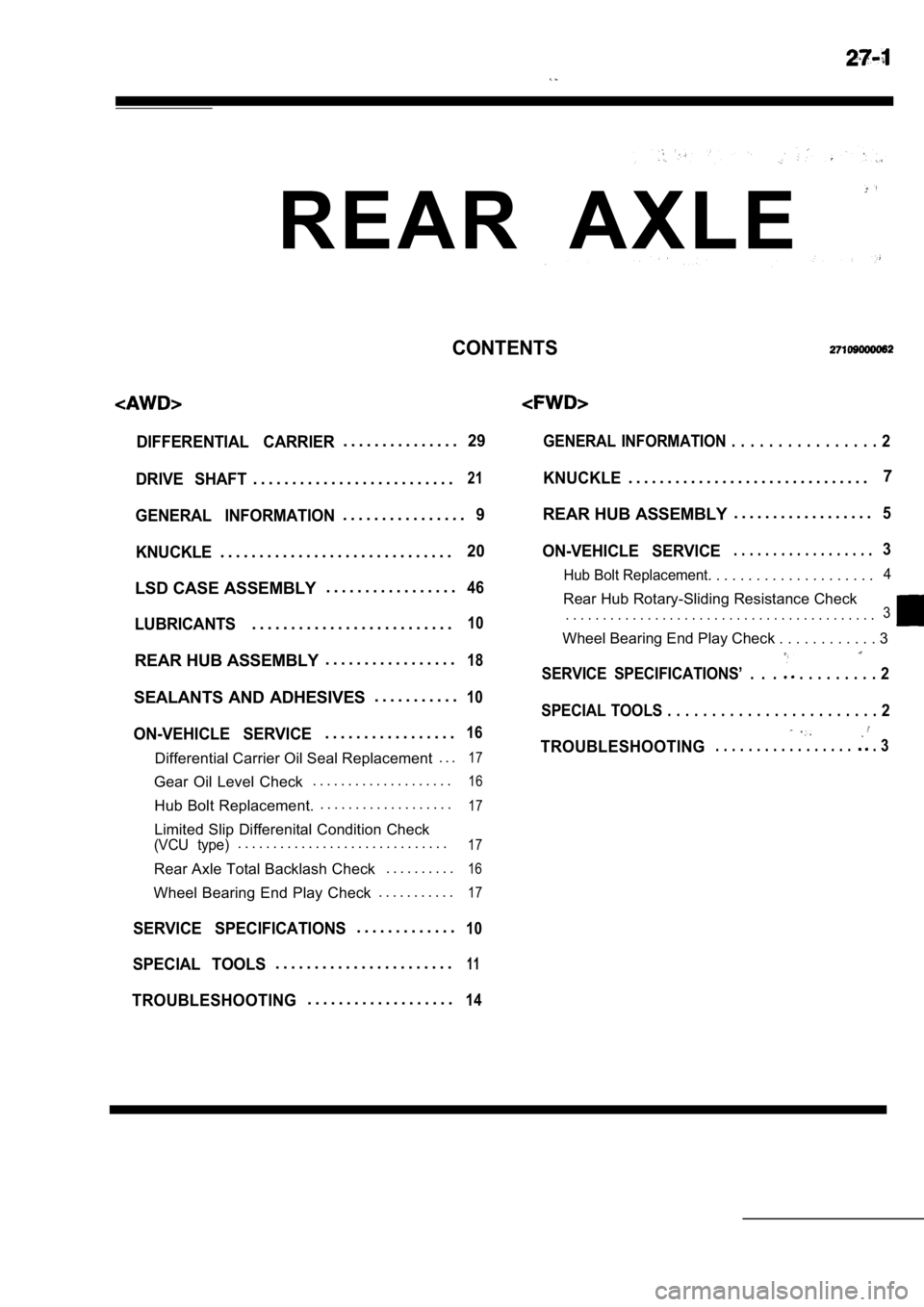
CONTENTS
DIFFERENTIAL CARRIER. . . . . . . . . . . . . . .29
DRIVE SHAFT
. . . . . . . . . . . . . . . . . . . . . . . . . .21
GENERAL INFORMATION. . . . . . . . . . . . . . . .9
KNUCKLE
. . . . . . . . . . . . . . . . . . . . . . . . . . . . . .20
LSD CASE ASSEMBLY . . . . . . . . . . . . . . . . .46
LUBRICANTS. . . . . . . . . . . . . . . . . . . . . . . . . .10
REAR HUB ASSEMBLY. . . . . . . . . . . . . . . . .18
SEALANTS AND ADHESIVES . . . . . . . . . . .10
ON-VEHICLE SERVICE. . . . . . . . . . . . . . . . .16
Differential Carrier Oil Seal Replacement
. . .17
Gear Oil Level Check. . . . . . . . . . . . . . . . . . . .16
Hub Bolt Replacement. . . . . . . . . . . . . . . . . . . .17
Limited Slip Differenital Condition Check(VCU type). . . . . . . . . . . . . . . . . . . . . . . . . . . . . .17
Rear Axle Total Backlash Check
. . . . . . . . . .16
Wheel Bearing End Play Check. . . . . . . . . . .17
SERVICE SPECIFICATIONS. . . . . . . . . . . . .10
SPECIAL TOOLS. . . . . . . . . . . . . . . . . . . . . . .11
TROUBLESHOOTING. . . . . . . . . . . . . . . . . . .14
GENERAL INFORMATION . . . . . . . . . . . . . . . .
2
KNUCKLE. . . . . . . . . . . . . . . . . . . . . . . . . . . . . . .7
REAR HUB ASSEMBLY . . . . . . . . . . . . . . . . . .
5
ON-VEHICLE SERVICE. . . . . . . . . . . . . . . . . .3
Hub Bolt Replacement. . . . . . . . . . . . . . . .
. . . . .4
Rear Hub Rotary-Sliding Resistance Check
. . . . . . . . . . . . . . . . . . . . . . . . . .
. . . . . . . . . . . . . . . .3
Wheel Bearing End Play Check . . . . . . . . . . .
. 3
SERVICE SPECIFICATIONS’ . . . . . . . . . . . . 2
SPECIAL TOOLS . . . . . . . . . . . . . . . . . . . . . . . . 2
TROUBLESHOOTING. . . . . . . . . . . . . . . . . . 3
Page 1536 of 2103
General Information/Service Specifications/
REAR AXLE Special Tools
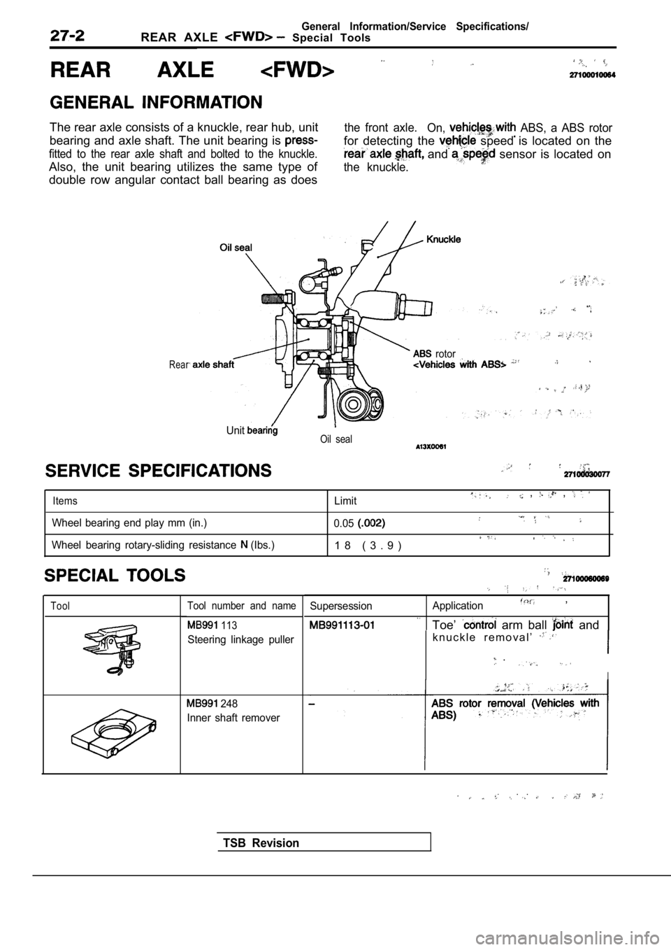
The rear axle consists of a knuckle, rear hub, unit
bearing and axle shaft. The unit bearing is
fitted to the rear axle shaft and bolted to the knuckle.
Also, the unit bearing utilizes the same type of
double row angular contact ball bearing as does
the front axle.
On, ABS, a ABS rotor
for detecting the speed is located on the
and sensor is located on
the knuckle.
Rear rotor
UnitOil seal
Items
Wheel bearing end play mm (in.)
Wheel bearing rotary-sliding resistance
(Ibs.) Limit
, ,
0.05
1 8 ( 3 . 9 )
ToolTool number and name
113
Steering linkage puller
248
Inner shaft remover
Supersession Application,
Toe’ arm ball and
k n u c k l e r e m o v a l ’
.
I
. .
TSB Revision