1990 MITSUBISHI SPYDER air condition
[x] Cancel search: air conditionPage 2049 of 2103
HEATER, AIR
AND VENTILATION On-vehicle Service
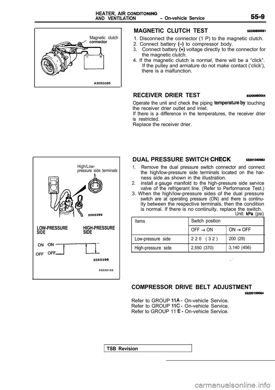
Magnetic clutch
High/Low-
pressure side terminals
LOW-PRESSURE HIGH-PRESSURESIDESIDE
0 0 0 0 0 1 6 9
MAGNETIC CLUTCH TEST
1. Disconnect the connector (1 P) to the magnetic c
lutch.
2. Connect battery
to compressor body.
3.Connect battery voltage directly to the connector for
the magnetic clutch.
4. If the magnetic clutch is normal, there will be a “click”.
If the pulley and armature do not make contact (‘cl ick’),
there is a malfunction.
RECEIVER DRIER TEST
Operate the unit and check the piping touching
the receiver drier outlet and inlet.
If there is a difference in the temperatures, the r eceiver drier
is restricted.
Replace the receiver drier.
DUAL PRESSURE SWITCH
1.Remove the dual pressure switch connector and conne ct
the high/low-pressure side terminals located on the har-
ness side as shown in the illustration.
2.installagauge manifold to the high-pressure side service
valve of the refrigerant line. (Refer to Performanc e Test.)
3. When the high/low-pressure sides of the dual pre ssure
switch are at operating pressure (ON) and there is continu-
ity between the respective terminals, then the condition
is normal. If there is no continuity, replace the s witch.
Unit: (psi)
ItemsSwitch position
OFF
ONON OFF
Low-pressure side2 2 0 ( 3 2 )200 (29)
High-pressure side2,550 (370) 3,140 (456)
COMPRESSOR DRIVE BELT ADJUSTMENT
Refer to GROUP On-vehicle Service.
Refer to GROUP
On-vehicle Service.
Refer to GROUP 11
On-vehicle Service.
TSB Revision
Page 2052 of 2103
HEATER, AIR
AND VENTILATION On-vehicle Service
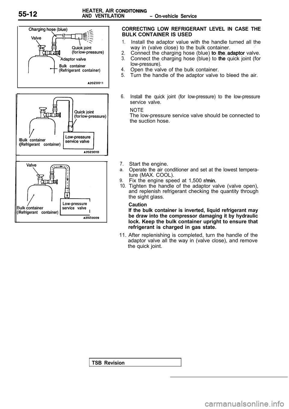
Bulk container
[Refrigerant container)
Refrigerant container)Bulk container
(Refrigerant container)
Low-pressure
service valve
I
CORRECTING LOW REFRIGERANT LEVEL IN CASE THE
BULK CONTAINER IS USED
1.
2.
3.
4.
5.
Install the adaptor value with the handle turned al l the
way in (valve close) to the bulk container.
Connect the charging hose (blue) valve.
Connect the charging hose (blue) to
quick joint (for
low-pressure).
Open the valve of the bulk container.
Turn the handle of the adaptor valve to bleed the a ir.
6.Install the quick joint (for low-pressure) to the low-pressure
service valve.
NOTE
The low-pressure service valve should be connected to
the suction hose.
7.
a.
9.
10.
Start the engine.
Operate the air conditioner and set at the lowest t empera-
ture (MAX. COOL).
Fix the engine speed at 1,500
Tighten the handle of the adaptor valve (valve open ),
and replenish refrigerant checking the quantity thr ough
the sight glass.
Caution
If the bulk container is inverted, liquid refrigera nt may
be draw into the compressor damaging it by hydrauli c
lock. Keep the bulk container upright to ensure that
refrigerant is charged in gas state.
11. After replenishing is completed, turn the handl e of the
adaptor valve all the way in (valve close), and rem ove
the quick joint.
TSB Revision
Page 2055 of 2103
HEATER, AIR
AND VENTILATION On-vehicle
REFRIGERANT LEAK REPAIR
LOST CHARGE
If the system has lost all charge due to a leak:
1. Evacuate the system. (See procedure.)
2. Charge the system with approximately one pound o f refrigerant.
3. Check for leaks.
4. Discharge the system.
5. Repair leaks.
6. Replace receiver drier.
Caution
Replacement filter-drier units must be sealed while in storage. The drier used
will absorb water/water vapor quickly upon exposure to the atmosphere. When installing a
drier, have all tools and supplies ready for quick reassembly to avoid keeping the system
open anylonger than necessary.
,
7. Evacuate and charge system.
LOW CHARGE
If the system has not lost all of its refrigerant c harge; locate and repair all leaks. If it is necess ary to
increase the system pressure to find the leak (beca use of an especially low charge) add refrigerant.
If it is possible to repair the leak without discha rging the refrigerant system, use the procedure for
low refrigerant level.
HANDLING TUBING AND FITTINGS
Kinks in the refrigerant tubing or sharp bends in t he refrigerant hose lines will greatly reduce the capacity
of the entire system. High pressures are produced i n the system when it is operating. Extreme care
must be exercised to make sure that all connections are pressure tight. Dirt and moisture can enter
the system when it is opened for repair or replacement of lines or components. The following precautions
must be observed. The system must be completely dis charged before opening any fitting or connection
in the refrigeration system. Open fittings with cau tion even after the system has been discharged. If
any pressure is noticed as a fitting is loosened, a llow trapped pressure to bleed off very slowly.
Never attempt to rebend formed lines to fit. Use th e correct line for the installation you are servicing.
A good rule for the flexible hose lines is keep the radius of all bends at least 10 times the diameter
of the hose. Sharper bends will reduce the flow of refrigerant.
The flexible hose lines should be routed so that th ey are at least 80 mm (3 in.) from the exhaust mani fold.
It is good practice to inspect all flexible hose lines at least once a year to make sure they are in g ood
condition and properly routed.
O-rings used on connections are not reusable.
TSB Revision
Page 2056 of 2103
6HEATER, AIR
AND VENTILATION On-vehicle Service
COMPRESSOR NOISE CHECK
You must first know the conditions when the noise occurs. These conditions are: weather, vehicle speed,
in gear or neutral, engine temperature or any other special conditions.
Noises that develop during A/C operation can often be misleading. For example: what sounds like a
failed front bearing or connecting rod, may be caus ed by loose bolts, nuts, mounting brackets, or a
loose clutch assembly. Verify accessory drive belt tension (power steering or generator).
Improper accessory drive belt tension can cause a m isleading noise when the compressor is engaged
and little or no noise when the compressor is disen gaged.
Drive belts are speed-sensitive. That is, at differ ent engine speeds, and depending upon belt tension,
belts can develop unusual noises that are often mis taken for mechanical problems within the compressor .
ADJUSTMENT
1. Select a quiet area for testing. Duplicate conditions as much as possible. Switch compressor on
and off several times to clearly identify compresso r noise. To duplicate high ambient
head pressure), restrict air flow through condenser . Install manifold gauge set sure discharge
pressure doesn’t exceed 2,070 (300 psi).
2. Tighten all compressor mounting bolts, clutch mo unting bolt, and compressor drive belt. Check to
assure clutch coil is tight (no rotation or wobble) .
3. Check refrigerant hoses for rubbing or interfere nce that can cause unusual noises.
4. Check refrigerant charge. (Refer to
5. Recheck compressor noise as in Step 1.
6. If noise still exists, loosen compressor mountin g bolts and retorque. Repeat Step 1.
7. If noise continues, replace compressor and repea t Step 1.
Revision
Page 2057 of 2103
HEATER, AIR
AND VENTILATION On-vehicle Service
IDLE-UP OPERATION CHECK
1,Before inspection and adjustment, set the f&w-
ing condition:
lEngine coolant temperature:
lLights, electric cooling fan and accessories: Set t o
OFF
lTransmission: Neutral (N or for vehicles with
l Steering wheel:
2. Check whether or not the idling speed is the sta ndard
value.
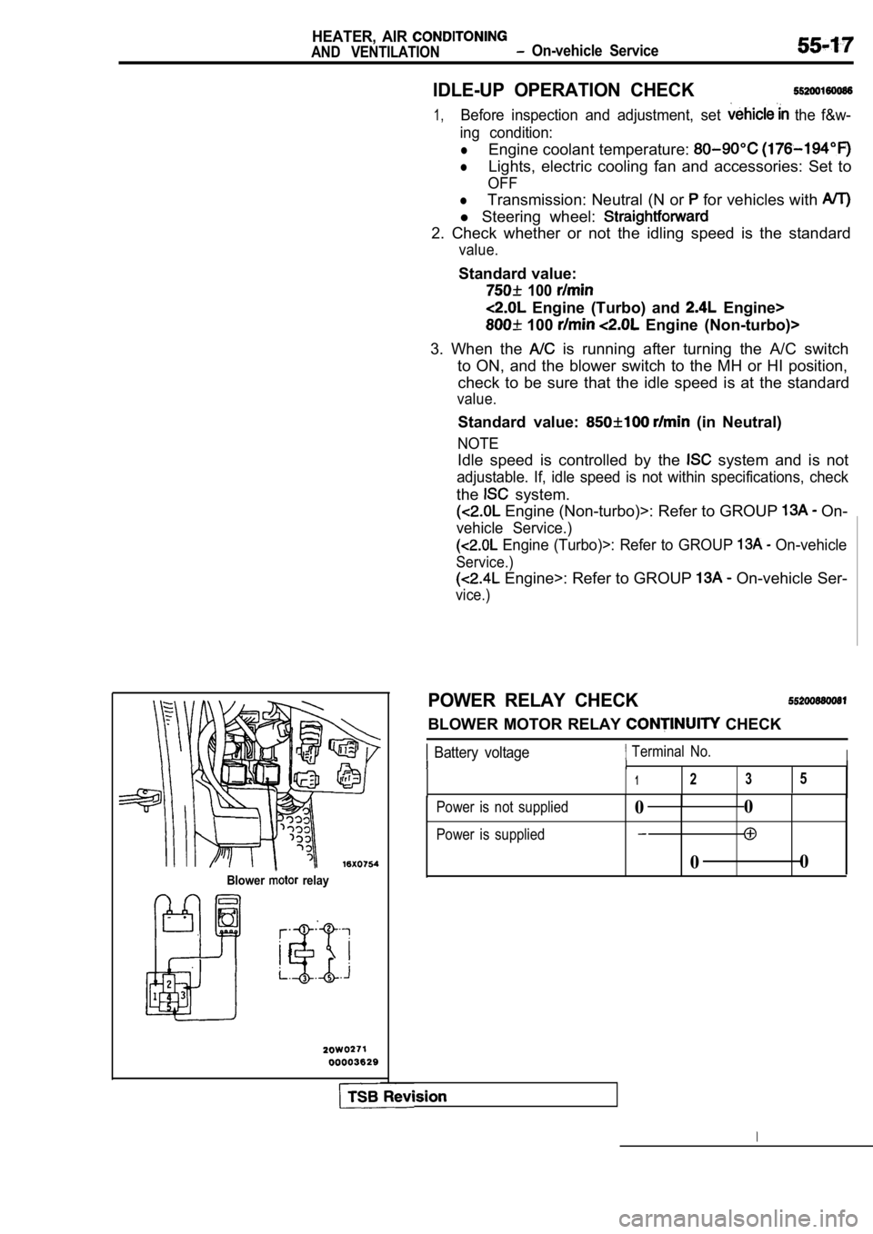
Blower relay
Standard value:
100
Engine (Turbo) and Engine>
100 Engine (Non-turbo)>
3. When the
is running after turning the A/C switch
to ON, and the blower switch to the MH or HI positi on,
check to be sure that the idle speed is at the stan dard
value.
Standard value: (in Neutral)
NOTE
Idle speed is controlled by the system and is not
adjustable. If, idle speed is not within specifications, check
the system.
Engine (Non-turbo)>: Refer to GROUP On-
vehicle Service.)
Engine (Turbo)>: Refer to GROUP On-vehicle
Service.)
Engine>: Refer to GROUP On-vehicle Ser-
vice.)
POWER RELAY CHECK
BLOWER MOTOR RELAY CHECK
Battery voltage Terminal No.III
1235
Power is not supplied
Power is supplied0 0
0 0
Page 2062 of 2103
55-22HEATER, AIR
AND Heater Control
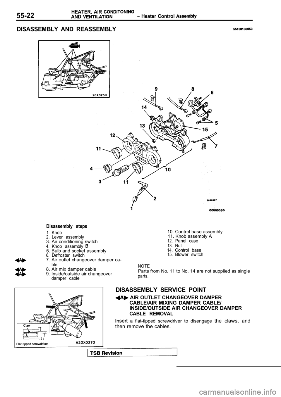
DISASSEMBLY AND REASSEMBLY
damper cable
Disassembly steps
1.Knob2.Lever assembly3. Air conditioning switch
4.Knob assembly5. Bulb and socket assembly6.Defroster switch7. Air outlet changeover damper ca-
ble8. Air mix damper cable
9. Inside/outside air changeover10. Control base assembly
11. Knob assembly A
12.Panel case
13.Nut14.Control base15.Blower switch
NOTE
Parts from No. 11 to No. 14 are not supplied as sin gle
parts.
DISASSEMBLY SERVICE POINT
AIR OUTLET CHANGEOVER DAMPER
CABLE/AIR MIXING DAMPER CABLE/INSIDE/OUTSIDE AIR CHANGEOVER DAMPER
CABLE REMOVAL
a flat-tipped screwdriver to disengage the claws, and
then remove the cables.
Page 2063 of 2103
HEATER, AIR
AND VENTILATION Air Conditioning Switch
AIR CONDITIONING SWITCH
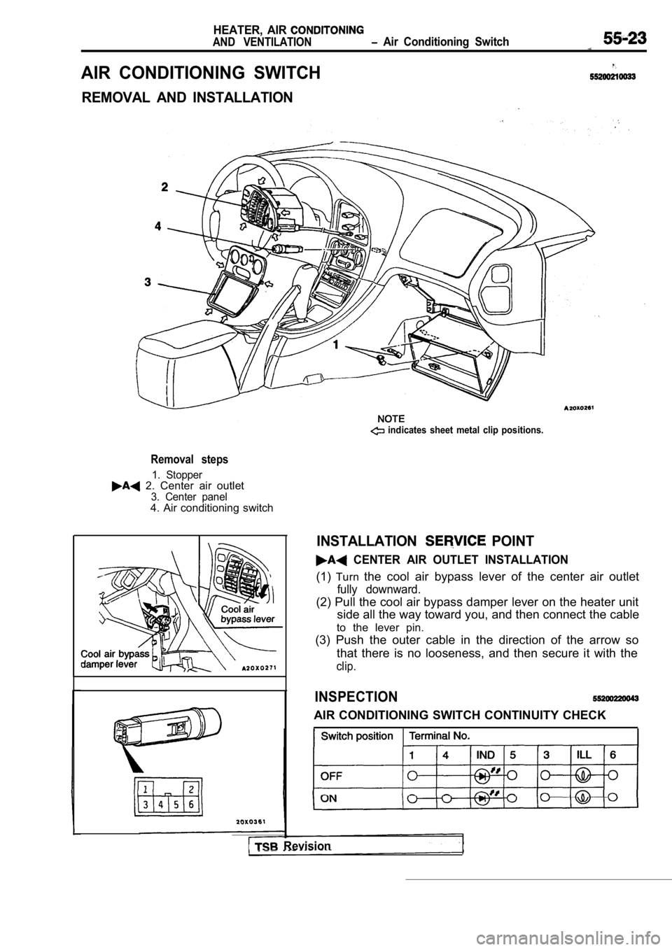
REMOVAL AND INSTALLATION
Removal steps
1. Stopper 2. Center air outlet3. Center panel4. Air conditioning switch
indicates sheet metal clip positions.
I Revision
INSTALLATION POINT
CENTER AIR OUTLET INSTALLATION
(1)Turn the cool air bypass lever of the center air outlet
fully downward.
(2) Pull the cool air bypass damper lever on the he ater unit
side all the way toward you, and then connect the c able
to the lever pin.
(3) Push the outer cable in the direction of the ar row so
that there is no looseness, and then secure it with the
clip.
INSPECTION
AIR CONDITIONING SWITCH CONTINUITY CHECK
Page 2070 of 2103
HEATER, AIR
AND VENTILATION Cooling Unit
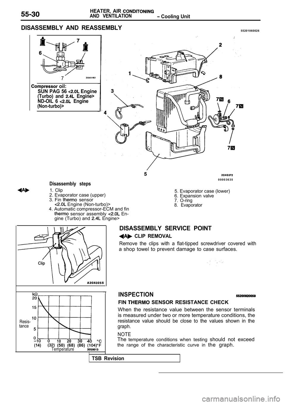
DISASSEMBLY AND REASSEMBLY5 5 2 0 1 0 6 0 0 2 6
7
oil:
SUN PAG 56
Engine
(Turbo) and Engine>
ND-OIL 6
Engine
(Non-turbo)>
0 0 0 0 3 6 3 5
Disassembly steps
1. Clip
2. Evaporator case (upper)
3. Fin sensor Engine (Non-turbo)>
4. Automatic compressor-ECM and fin
sensor assembly En-
gine (Turbo) and Engine> 5. Evaporator case (lower)
6. Expansion valve
7. O-ring
8. Evaporator
Resis-
tance
1 02030 40(14) (50) (68) (86) Temperature
INSPECTION
FIN SENSOR RESISTANCE CHECK
When the resistance value between the sensor termin als
is measured under two or more temperature condition s, the
resistance value should be close to the values show n in the
graph.
NOTE
Thetemperature conditions when testing should not exceed
the range of the characteristic curve in the graph.
TSB Revision
DISASSEMBLY SERVICE POINT
CLIP REMOVAL
Remove the clips with a flat-tipped screwdriver cov ered with
a shop towel to prevent damage to case surfaces.