1990 MITSUBISHI SPYDER air condition
[x] Cancel search: air conditionPage 2004 of 2103
SRS General Information.
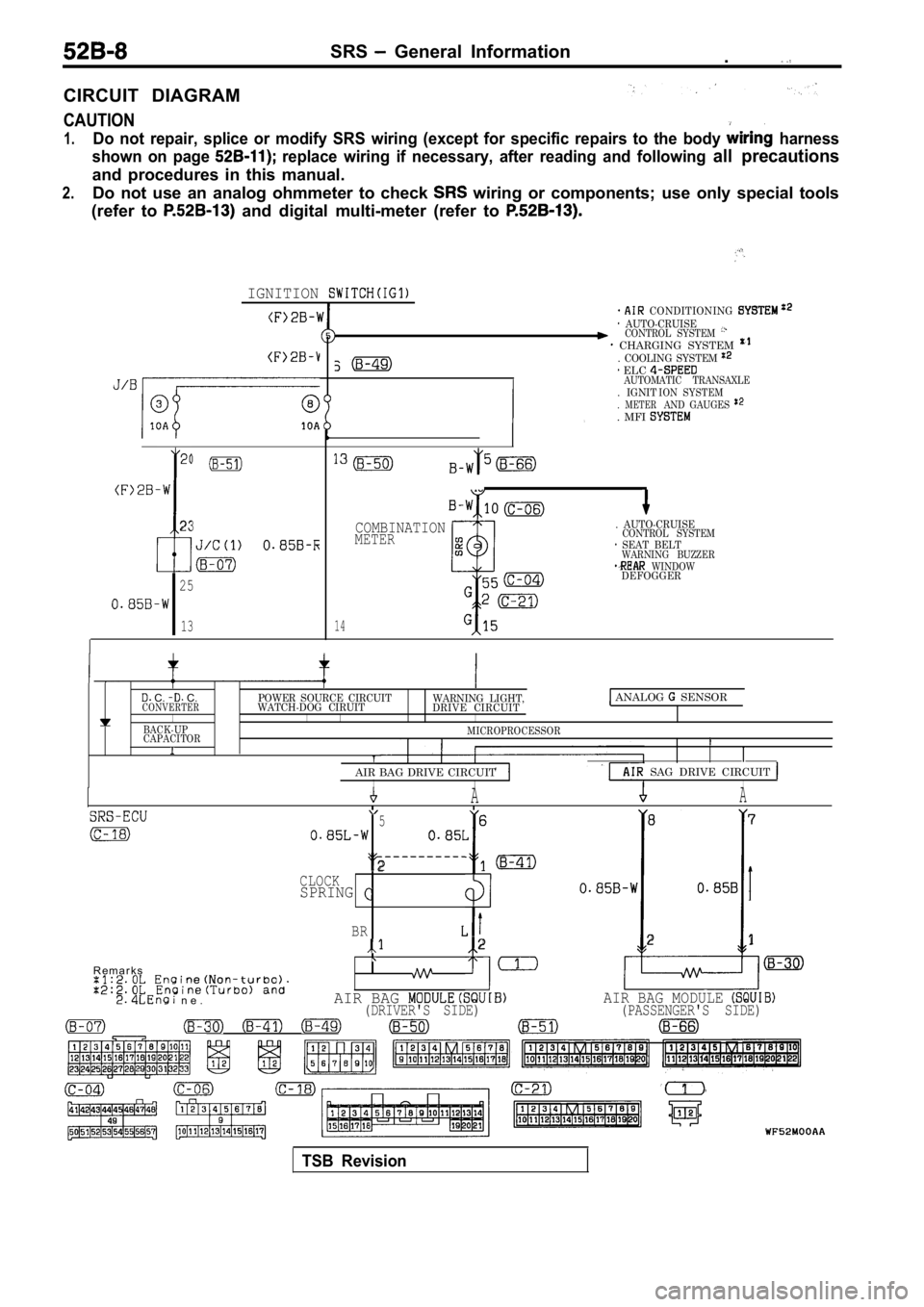
CIRCUIT DIAGRAM
CAUTION
1.Do not repair, splice or modify SRS wiring (except for specific repairs to the body harness
shown on page
replace wiring if necessary, after reading and fol lowing all precautions
and procedures in this manual.
2.Do not use an analog ohmmeter to check wiring or components; use only special tools
(refer to
and digital multi-meter (refer to
IGNITION
23
I
25
13
CONDITIONING AUTO-CRUISECONTROL SYSTEM CHARGING SYSTEM . COOLING SYSTEM
. IGNIT. METER. MFI
ELC AUTOMATIC TRANSAXLE ION SYSTEMAND GAUGES
14
COMBINATIONMETER
. AUTO-CRUISECONTROL SYSTEM SEAT BELTWARNING BUZZER WINDOWDEFOGGER
C. C.POWER SOURCE CIRCUITCONVERTERWATCH-DOG CIRUIT WARNING LIGHT,
DRIVE CIRCUIT ANALOG SENSOR
I IIIBACK-UP
CAPACITORMICROPROCESSORI
AIR BAG DRIVE CIRCUIT
SAG DRIVE CIRCUIT IIIAA
5 6 8
7
2CLOCKSPRINGI
BR2 21
R e m a r k s
n e .AIR BAG AIR BAG MODULE (DRIVER'S SIDE) (PASSENGER'S SIDE)
TSB Revision
Page 2011 of 2103
SRS
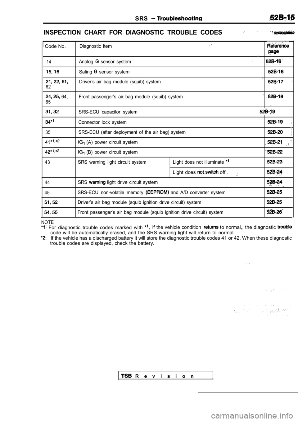
INSPECTION CHART FOR DIAGNOSTIC TROUBLE CODES
Code No.Diagnostic item
14Analog sensor system
Safing sensor system
Driver’s air bag module (squib) system
62
64, Front passenger’s air bag module (squib) system
65
SRS-ECU capacitor system
Connector lock system
35SRS-ECU (after deployment of the air bag) system
(A) power circuit system
(B) power circuit system
43SRS warning light circuit system Light does not illuminate
Light does off
44SRS light drive circuit system
45SRS-ECU non-volatile memory and A/D converter system’
Driver’s air bag module (squib ignition drive circuit) system
Front passenger’s air bag module (squib ignition dr ive circuit) system
NOTE
For diagnostic trouble codes marked with if the vehicle condition to normal,, the diagnostic
code will be automatically erased, and the SRS warn ing light will return to normal.
If the vehicle has a discharged battery it will store the diagnostic trouble codes 41 or 42. When thes e diagnostic
trouble codes are displayed, check the battery.
R e v i s i o n1
Page 2015 of 2103
![MITSUBISHI SPYDER 1990 Service Repair Manual SRS Troubleshooting
Code No. 31 or 32 SRS-ECU capacitor systemProbable cause
[Comment]l Malfunction of These diagnostic trouble codes are output if the vo ltage at the SRS-ECU capacitor
term MITSUBISHI SPYDER 1990 Service Repair Manual SRS Troubleshooting
Code No. 31 or 32 SRS-ECU capacitor systemProbable cause
[Comment]l Malfunction of These diagnostic trouble codes are output if the vo ltage at the SRS-ECU capacitor
term](/manual-img/19/57345/w960_57345-2014.png)
SRS Troubleshooting
Code No. 31 or 32 SRS-ECU capacitor systemProbable cause
[Comment]l Malfunction of These diagnostic trouble codes are output if the vo ltage at the SRS-ECU capacitor
terminals is higher (No. 31) or lower (No. 32) than the value for 5 seconds
or more.
However, if diagnostic trouble code Nos. 41 and 42 are being output due to a drop
in battery voltage, code No. 32 will not be detecte d.
Insulating tape
Caution
Turn the ignition key to the “LOCK” position, disco nnect
the negative battery cable and tape the terminal.
Wait at least 60 seconds after disconnecting the ba ttery
cable before doing any further work. (Refer to
Battery cable
Replace the SRS-ECU.
Code No. 34 Connector lock system Probable cause
[Comment]l Malfunction of connectors
This diagnostic trouble code is output when the SRS -ECU connector is connectedl
Malfunction of SRS-ECU
improperly.However, if the vehicle condition returns to normal , diagnostic trouble code No. 34
will be automatically erased, and the SRS light will switch off.
insulating tape
Battery cable
Caution
Turn the ignition key to the “LOCK” position, disco nnect
the negative battery cable and tape the terminal.
Wait at least 60 seconds after disconnecting the ba ttery
cable before doing any further work. (Refer to P.
Check trouble symptom.
OKNG
Repair
Replace the SRS-ECU.
TSB Revision
Page 2018 of 2103
![MITSUBISHI SPYDER 1990 Service Repair Manual SRS Troubleshooting
Code No. 42 (B) power circuit system Probable cause
[Comment]l Malfunction of harnesses or connectorsThis diagnostic trouble code is output if the voltage betw MITSUBISHI SPYDER 1990 Service Repair Manual SRS Troubleshooting
Code No. 42 (B) power circuit system Probable cause
[Comment]l Malfunction of harnesses or connectorsThis diagnostic trouble code is output if the voltage betw](/manual-img/19/57345/w960_57345-2017.png)
SRS Troubleshooting
Code No. 42 (B) power circuit system Probable cause
[Comment]l Malfunction of harnesses or connectorsThis diagnostic trouble code is output if the voltage between the terminaland the ground is lower than the specified value fo r a continuous period of secondsor more.
However, if the vehicle condition returns to normal , diagnostic trouble code NO. 42
will be automatically erased, and the SRS warning l ight will switch off.
Battery
cableI
SRS check harness
Caution
Turn the ignition key to the “LOCK” position, disco nnect
the negative battery cable and tape the terminal.
Wait at least 60 seconds after disconnecting the battery
cable before doing any further work. (Refer to P.
Measure at SRS check harness
connector (5). l Disconnect SRS-ECU connector
l Connect SRS check harness
connector (3).
lContinuity between (20)
OK: Continuity
0 0 0 0 3 9 2 4
OK
Measure at SRS check harness connector (5).
l Disconnect SRS-ECU connector
l Connect SRS check harness connector (3)
l Ignition switch: ON
l Voltage between terminal (13) and ground
OK:
or more
O K
I
the
OK
Check trouble symptom.
NG
NG C h e c k t h eNGfollowingconnectors: and
OK
ICheck trouble symptom.
NG
Repair
TSB Revision
Page 2041 of 2103
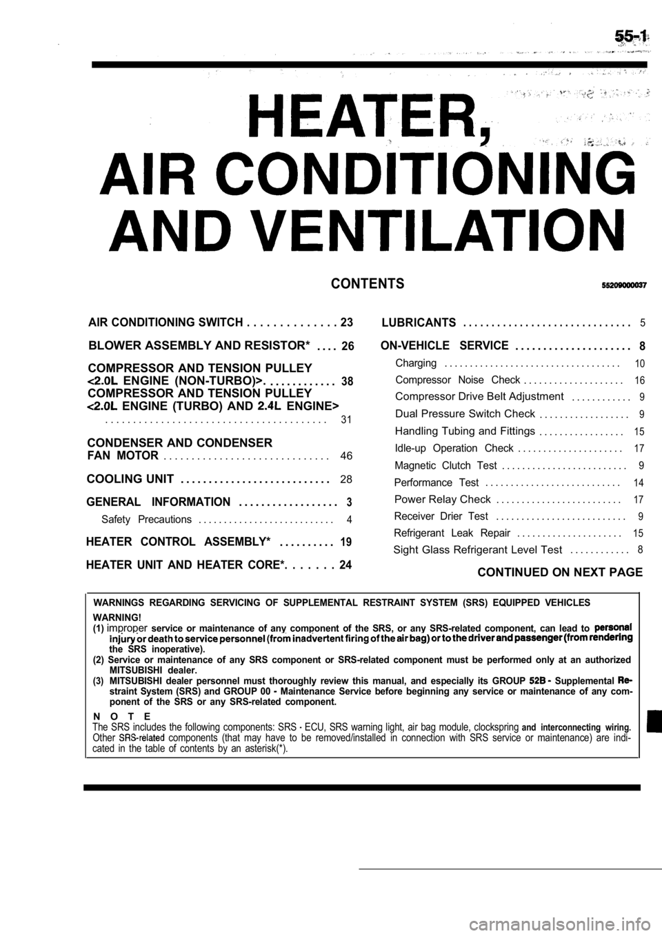
CONTENTS
AIR CONDITIONING SWITCH . . . . . . . . . . . . . . 23
LUBRICANTS. . . . . . . . . . . . . . . . . . . . . . . . . . . . . .5
BLOWER ASSEMBLY AND RESISTOR*
. . . .26
COMPRESSOR AND TENSION PULLEY
ENGINE (NON-TURBO)>.. . . . . . . . . . . .38
COMPRESSOR AND TENSION PULLEY
ENGINE (TURBO) AND ENGINE>
ON-VEHICLE SERVICE. . . . . . . . . . . . . . . . . . . . .8
Charging. . . . . . . . . . . . . . . . . . . . . . . . . . . . . . . . . . .10
Compressor Noise Check. . . . . . . . . . . . . . . . . . . .16
Compressor Drive Belt Adjustment . . . . . . . . . . . .9
. . . . . . . . . . . . . . . . . . . . . . . . . . . . . . . . . . . . . . . .31Dual Pressure Switch Check. . . . . . . . . . . . . . . . . .9
Handling Tubing and Fittings. . . . . . . . . . . . . . . . .15
CONDENSER AND CONDENSER
46Idle-up Operation Check. . . . . . . . . . . . . . . . . . . . .17FAN MOTOR. . . . . . . . . . . . . . . . . . . . . . . . . . . . . .Magnetic Clutch Test. . . . . . . . . . . . . . . . . . . . . . . . .9
COOLING UNIT . . . . . . . . . . . . . . . . . . . . . . . . . . . 28
GENERAL INFORMATION3. . . . . . . . . . . . . . . . . .
Performance Test. . . . . . . . . . . . . . . . . . . . . . . . . . .14
Power Relay Check . . . . . . . . . . . . . . . . . . . . . . . . .17
Safety Precautions. . . . . . . . . . . . . . . . . . . . . . . . . . .4Receiver Drier Test. . . . . . . . . . . . . . . . . . . . . . . . . .9
. . . . . . . . . . . . . . . . . . . . .15HEATER CONTROL ASSEMBLY*19Refrigerant Leak Repair. . . . . . . . . .
Sight Glass Refrigerant Level Test . . . . . . . . . . . .8
HEATER UNIT AND HEATER CORE*. . . . . . . 24CONTINUED ON NEXT PAGE
WARNINGS REGARDING SERVICING OF SUPPLEMENTAL RESTRA
INT SYSTEM (SRS) EQUIPPED VEHICLES
WARNING!
(1)
improperservice or maintenance of any component of the SRS, or any SRS-related component, can lead to
the SRS inoperative).
(2) Service or maintenance of any SRS component or SRS-related component must be performed only at an authorized
MITSUBISHI dealer.
(3)MITSUBISHI dealer personnel must thoroughly review this manual, and especially its GROUP Supplemental straint System (SRS) and GROUP 00 Maintenance Service before beginning any service or maintenance of any com-
ponent of the SRS or any SRS-related component.
N O T EThe SRS includes the following components: SRS ECU, SRS warning light, air bag module, clocksprin g and interconnecting wiring.Other components (that may have to be removed/installed in connection with SRS service or maintenance) are indi-
cated in the table of contents by an asterisk(*).
Page 2043 of 2103
HEATER, AIR
AND VENTILATION General Information
GENERAL INFORMATION
The heater system uses a two-way-flow full-air-mixThe A/C system is basically the same as the
system that features high performance and lowtional system, but a new refrigerant system
operating noise, and includes an independent facebeen adopted as a response to
air blowing function and a air bypass function.use of chlorofluorocarbons. ,
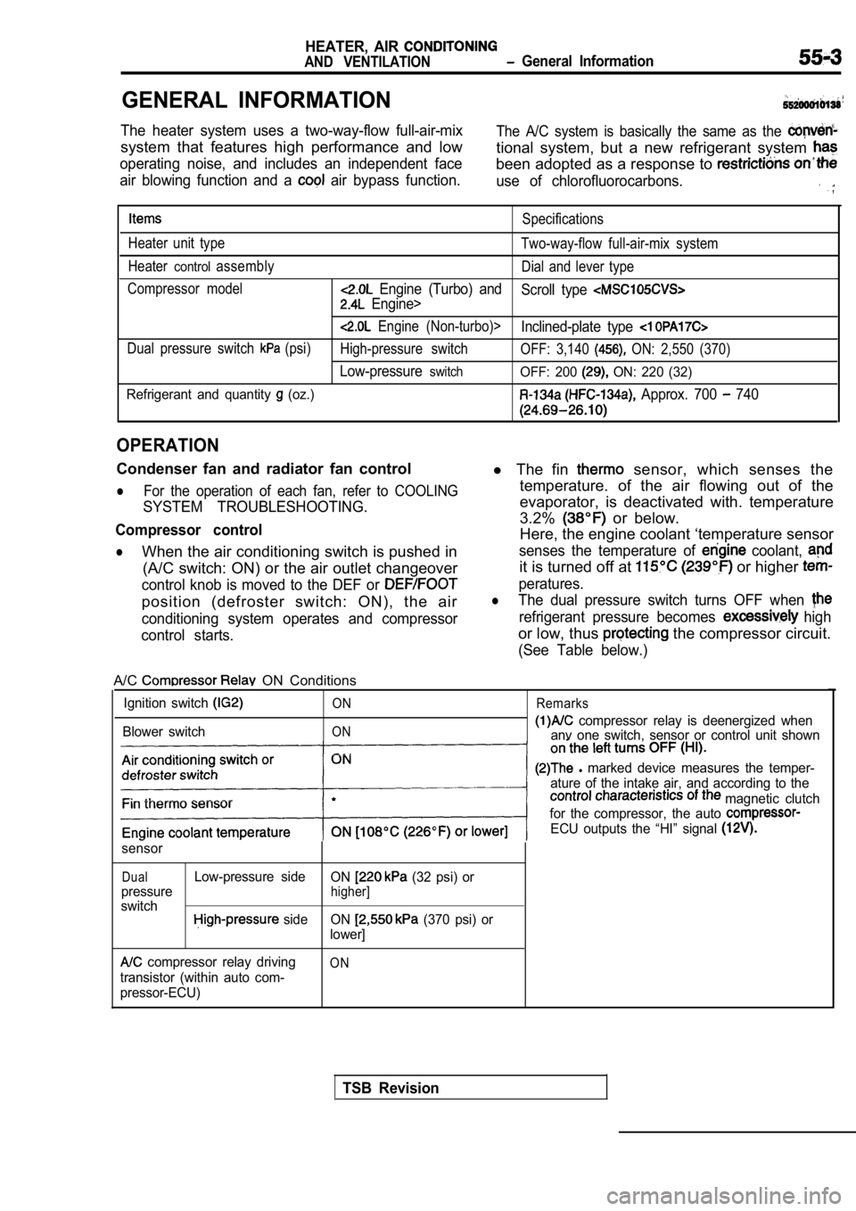
Specifications
Heater unit type Two-way-flow full-air-mix system
Heater
controlassembly Dial and lever type
Compressor model
Engine (Turbo) and Scroll type
Engine>
Engine (Non-turbo)>Inclined-plate type
Dual pressure switch (psi)High-pressure switch OFF: 3,140 ON: 2,550 (370)
Low-pressureswitchOFF: 200 ON: 220 (32)
Refrigerant and quantity
(oz.) Approx. 700 740
OPERATION
Condenser fan and radiator fan control
lFor the operation of each fan, refer to COOLING
SYSTEM TROUBLESHOOTING.
Compressor control
lWhen the air conditioning switch is pushed in (A/C switch: ON) or the air outlet changeover
control knob is moved to the DEF or
position (defroster switch: ON), the air
conditioning system operates and compressor
control starts.
l The fin sensor, which senses the
temperature. of the air flowing out of the
evaporator, is deactivated with. temperature
3.2%
or below.
Here, the engine coolant ‘temperature sensor
senses the temperature of coolant,
it is turned off at or higher
peratures.
lThe dual pressure switch turns OFF when
refrigerant pressure becomes high
or low, thus the compressor circuit.
(See Table below.)
A/C ON Conditions
Ignition switch
Blower switch
ON
ON Remarks
compressor relay is deenergized when
anv one switch, sensor or control unit shown
l marked device measures the temper-
ature of the intake air, and according to the
magnetic clutch
for the compressor, the auto
ECU outputs the “HI” signal
sensor
DualLow-pressure side ON (32 psi) or
pressure
higher]
switch side ON (370 psi) or
lower]
compressor relay driving
transistor (within auto com-
pressor-ECU)ON
TSB Revision
Page 2046 of 2103

HEATER, AIR
AND VENTILATION Troubleshooting
TROUBLESHOOTING
PROCEDURES
Trouble
symptom
When the ignitior
switch is “ON”,
the
does not
operate.
conditioning
does not
when
he air outlet
knob is
noved to the
or
position. Problem cause
compressor clutch relay
is defective
Magnetic clutch is defective
Refrigerant leak or overfilling
of refrigerant
Dual pressure switch is defec-
tive
A/C switch is defective Blower switch is defective
Fin
sensor is defective
Refrigerant temperature switch
is defective
Engine (Tur-
bo) and
Engine>
Automatic compressor-ECM
is defective
Revolution pick up sensor is
defective
Engine (Non-turbo)>
A/C compressor relay is de-
fective
1
Dual pressure switch is defec-
tive
Defroster switch is defective
TSB Revision
Magnetic clutch is defective
Refrigerant leak or overfilling
of refrigerant Remedy
Reference ReferencepagepageEngine
Engine(Non-turbo) (Turbo) Engine
Replace A/C compressor clutch 55-1855-18
relay
Replace the armature plate, rotor55-34
or clutch coil
Replenish the refrigerant, repair
0
the leak or take out some of therefrigerant
Replace the dual pressure switch 55-45
Replace the A/C switch 55-2355-23
Replace the blower switch55-22 55-22
Replace the fin sensor
Replace the refrigerant tempera-
ture switch
Replace the automatic
Replace the revolution pick up
sensor
55-26
Replace A/C compressor clutch55-18
relay
Replace the armature plate, rotor55-34
or clutch coil
Replenish the refrigerant, repair
the leak or take out some of the
refrigerant
Replace the dual pressure switch55-45
the defroster switch55-22 55-22
the blower switch55-225 5 - 2 2
temperature Replace the refrigerant tempera-
is defective
ture switch
compressor-ECU isReplace the automatic 55-26
sor-ECU
pick up sensor is
Replace the revolution pick up
sensor Engine
Page 2048 of 2103
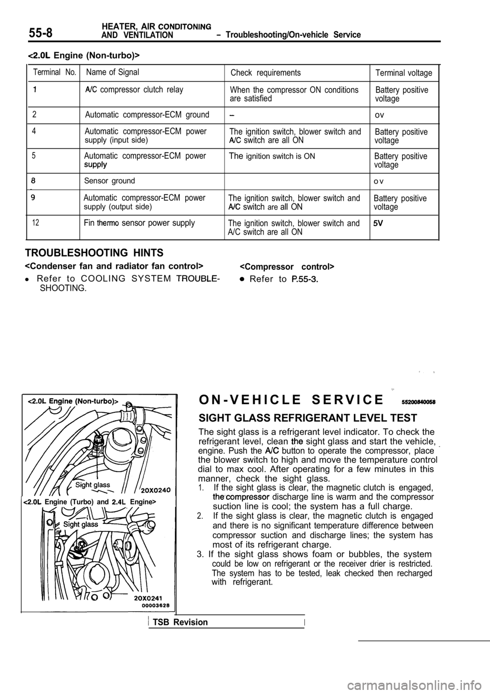
55-8HEATER, AIR
AND VENTILATION Troubleshooting/On-vehicle Service
Engine (Non-turbo)>
12
Sensor ground
Automatic compressor-ECM power
supply (output side)
Fin sensor power supply
o v
The ignition switch, blower switch andBattery positive
switch areall ONvoltage
The ignition switch, blower switch and
A/C switch are all ON
TROUBLESHOOTING HINTS
l R e f e r t o C O O L I N G S Y S T E M
SHOOTING.
Refer to
Terminal No.Name of Signal
Check requirements Terminal voltage
compressor clutch relay
When the compressor ON conditions Battery positive
are satisfied voltage
2Automatic compressor-ECM groundov
4Automatic compressor-ECM power
The ignition switch, blower switch and Battery positive
supply (input side) switch are all ONvoltage
5Automatic compressor-ECM powerTheignition switch is ONBattery positive
voltage
Engine (Turbo) and Engine>I
O N - V E H I C L E S E R V I C E
SIGHT GLASS REFRIGERANT LEVEL TEST
The sight glass is a refrigerant level indicator. T o check the
refrigerant level, clean
sight glass and start the vehicle,
engine. Push the button to operate the compressor, place
the blower switch to high and move the temperature control
dial to max cool. After operating for a few minutes in this
manner, check the sight glass.
1.If the sight glass is clear, the magnetic clutch is engaged,
discharge line is warm and the compressor
suction line is cool; the system has a full charge.
2.If the sight glass is clear, the magnetic clutch is engaged
and there is no significant temperature difference between
compressor suction and discharge lines; the system has
most of its refrigerant charge.
3. If the sight glass shows foam or bubbles, the sy stem
could be low on refrigerant or the receiver drier is restricted.
The system has to be tested, leak checked then rech arged
with refrigerant.
TSB RevisionI