Page 1711 of 2103
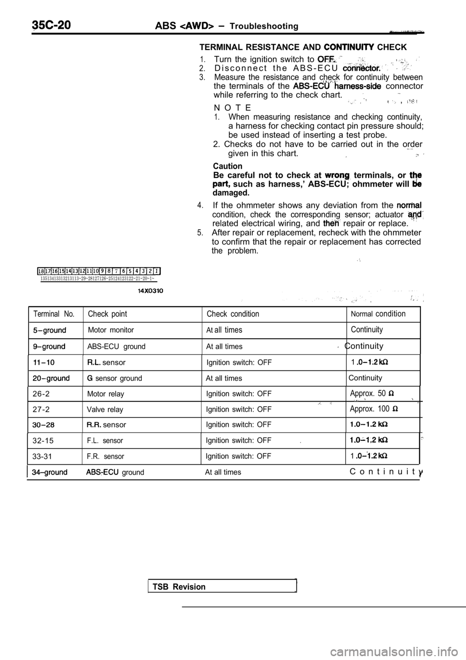
RESISTANCE AND CONTINUITY CHECK
1. Turn. the ignition switch to OFF.
2. Disconnect the ABS-ECU connector.
3.Measure the resistance and check for continuity bet ween
the terminals of the ABS-ECU connector
while referring to the check chart.
measuring resistance and checking continuity,
a ‘harness for checking contact pin pressure should
be used instead of inserting a test probe.
2.
Checks do not have to be carried out in the order
given
this chart.
Caution
or continuity checks are performed on
the
damage to the
and/or ohmmeter may occur.
care to prevent this!
If the ohmmeter shows any deviation from the norma l
condition, check the corresponding sensor, actuator and
related electrical wiring, and then repair or replace.
5. After repair or replacement, recheck with the oh mmeter
to confirm that the repair or replacement has corre cted
t h e p r o b l e m .
7
sensor switch: OFF
ABS-ECU groundAt all timesContinuity
TSB Revision
Page 1744 of 2103

ABS
Caution
1.If movements are made when driving at speed, or when driving on road
with low frictional resistance, or when passing over bumps, the ABS may
sudden braking is not being applied. of this, when getting
2.
check if the problem occurred while driving under s uch conditions
During ABS operation changes in the feeling of the brake pedal occur or
may not be able to be depressed). Such changes are due to in hydraulic
pressure inside the brake line to prevent, the whee ls from locking,
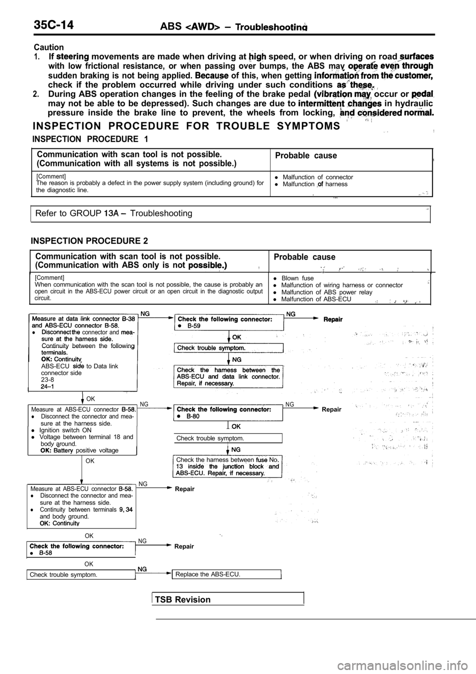
I N S P E C T I O N P R O C E D U R E F O R T R O U B L E S Y M P T O M S ,
INSPECTION PROCEDURE 1
Communication with scan tool is not possible. Probable cause
(Communication with all systems is not possible.)
[Comment]l Malfunction of connector
The reason is probably a defect in the power supply system (including ground) for
the diagnostic line. l
Malfunction harness
Refer to GROUP Troubleshooting
INSPECTION PROCEDURE 2
Communication with scan tool is not possible.
(Communication with ABS only is not Probable cause
,
[Comment]l Blown fuse
When communication with the scan tool is not possib le, the cause is probably an
l Malfunction of wiring harness or connector
open circuit in the ABS-ECU power circuit or an ope n circuit in the diagnostic output
circuit.l Malfunction of ABS power relay
l Malfunction of ABS-ECU
,
l connector and
Continuity between the following
ABS-ECU
to Data link
connector side
23-8
OKNGMeasure at ABS-ECU connector lDisconnect the connector and mea-sure at the harness side.
N G Repair
l Ignition switch ON
l Voltage between terminal 18 and
bodv around. Check trouble symptom.
I positive voltage
OKCheck the harness between No
NG
Measure at ABS-ECU connector
lDisconnect the connector and mea-sure at the harness side.lContinuity between terminals and body ground.OK:
Repair
l
OKNG Repair
OK
Check trouble symptom. Replace the ABS-ECU.
TSB Revision
Page 1747 of 2103
, , .
PROCEDURE 7
Break operation is
[Comment] o f w h e e l This depending on the driving conditions and the road surface conditions, so ‘ M a l f u n c t i o n _ _
problem diagnosis is difficult. However, if a normal diagnostic trouble code is displayed,l
carry out the following Malfunction of bearing. . .l of: .
W h e e l s p e e d -NG: Repair(Refer to
N G N G speed sensor check(Refer to GROUP -Wheel SpeedReplace the wheel speed sensor.
OKSensor Check.)
OK
Hydraulic unit check (Refer to N GABS rotor check (Refer to Replace the rotor.
OK
Wheel bearing end play check
Refer to GROUP 26 On-vehicle Repair
Refer to GROUP 27
On-vehide
Service.
Check trouble symptom.
N G
ABS-ECU connector Disconnect the connector and measure at the harness side.
Resistance value between termi-nals and
NG Repair
O K
The sensor harness and connector s h o u l d b e m o v e d w h i l e t h e s e
inspections are carried out.
the .
TSB Revision
Page 1750 of 2103

ABS Troubleshooting
TERMINAL RESISTANCE AND
CHECK
7 13513413313213113~29~28127126~25124123122~21~20~1~
1.
2.
3.
4.
5.
Turn the ignition switch to
D i s c o n n e c t t h e A B S - E C U
Measure the resistance and check for continuity bet ween
the terminals of the connector
while referring to the check chart.
N O T E
,
1.When measuring resistance and checking continuity,
a harness for checking contact pin pressure should;
be used instead of inserting a test probe.
2. Checks do not have to be carried out in the orde r
given in this chart.
Caution
Be careful not to check at terminals, or
such as harness,’ ABS-ECU; ohmmeter will
damaged.
If the ohmmeter shows any deviation from the
condition, check the corresponding sensor; actuator
related electrical wiring, and repair or replace.
After repair or replacement, recheck with the ohmmeter
to confirm that the repair or replacement has corre cted
the problem.
Terminal No.Check point Check conditionNormalcondition
Motor monitorAtall timesContinuity
ABS-ECU ground At all times Continuity
sensor
sensor groundIgnition switch: OFF
1At all timesContinuity
2 6 - 2
Motor relay
2 7 - 2Valve relay
sensor
Ignition switch: OFF
Ignition switch: OFF
Ignition switch: OFFApprox. 50
Approx. 100
32-15F.L. sensor
33-31F.R. sensor
Ignition switch: OFF
Ignition switch: OFF.
1
ground At all timesC o n t i n u i t y
I’
TSB Revision
Page 1784 of 2103

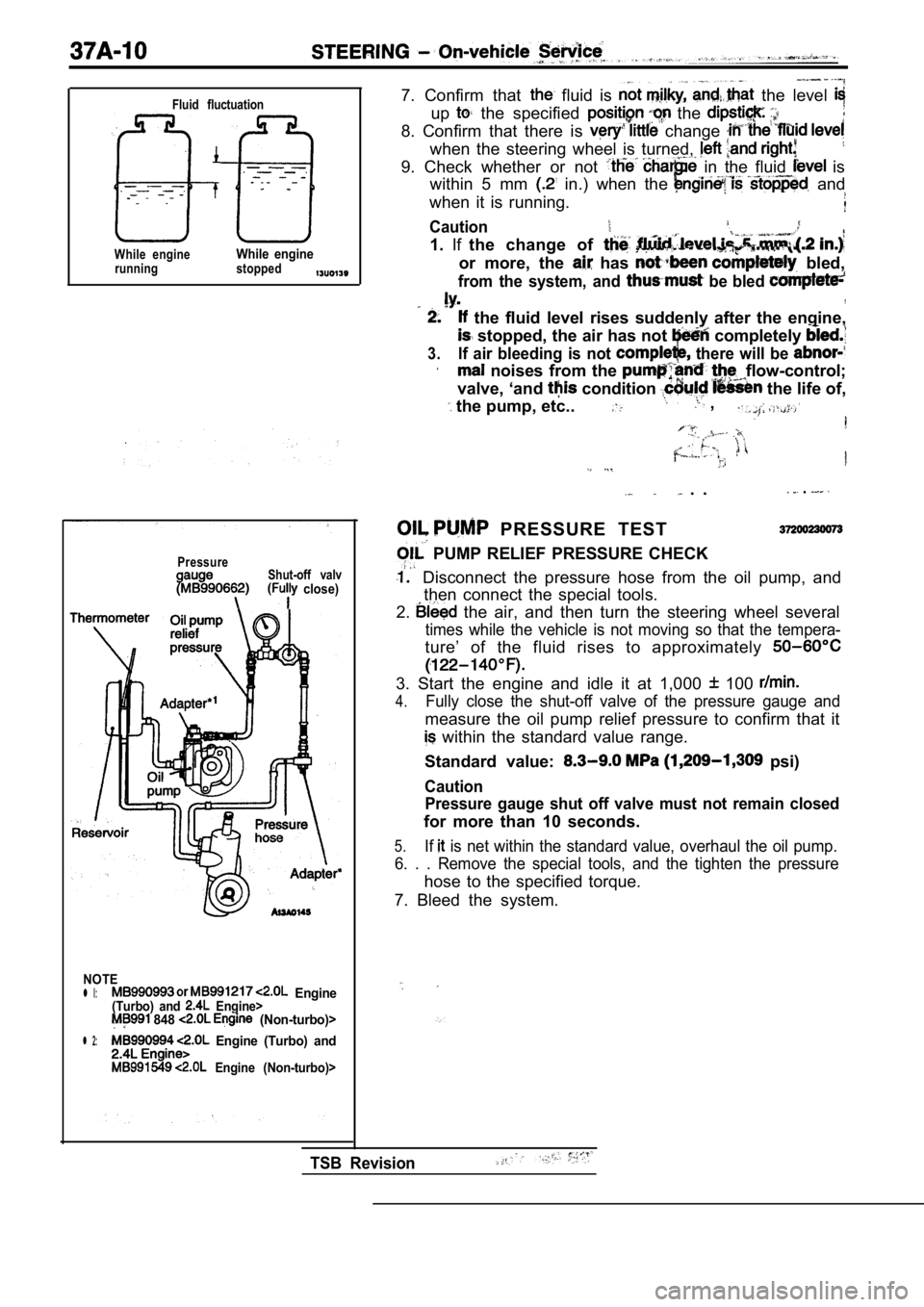
Fluid fluctuation
While engineWhile enginerunning stopped
PressureShut-off valv close)
NOTE
l l: Engine(Turbo) and Engine> 848 (Non-turbo)>
l 2: Engine (Turbo) and
Engine (Non-turbo)>
7. Confirm that fluid is the level
up the specified the
8. Confirm that there is change
when the steering wheel is turned,
9. Check whether or not in the fluid is
within 5 mm
in.) when the and
when it is running.
Caution
1. Ifthe change of
or more, the has bled,
from the system, and be bled ,
the fluid level rises suddenly after the engine,
stopped, the air has not completely
3.If air bleeding is not there will be
noises from the flow-control;
valve, ‘and
condition the life of,
the pump, etc.. ,
. . .
PRESSURE TEST
PUMP RELIEF PRESSURE CHECK
Disconnect the pressure hose from the oil pump, an d
then connect the special tools.
2.
the air, and then turn the steering wheel several
times while the vehicle is not moving so that the t empera-
ture’ of the fluid rises to approximately
3. Start the engine and idle it at 1,000 100
4.Fully close the shut-off valve of the pressure gaug e and
measure the oil pump relief pressure to confirm tha t it
within the standard value range.
Standard value:
psi)
Caution Pressure gauge shut off valve must not remain close d
for more than 10 seconds.
5.If is net within the standard value, overhaul the oil pump.
6. . . Remove the special tools, and the tighten th e pressure
hose to the specified torque.
7. Bleed the system.
TSB Revision
Page 1785 of 2103
STEERING On-vehicle’ Service
PressureShut-off valve(Fully open)
I
Thermometer
NOTE Engine
(Turbo) and
548 Engine (Non-turbo)>
l 2: Engine (Turbo) and
549 Engine (Non-turbo)>
. .. . ..
CHECKING
UNDER NO-LOAD
1. Disconnect. the pressure hose from the oil pump, and
then connect the special tools.
2. Bleed the air, and then turn the steering
several:
times the vehicle is not moving so that the tempera-
ture the fluid rises to approximately
3. the and idle it 100
4.Check whether or not the hydraulic pressure is
dard value when no-load conditions fully
opening the shut-off
of the pressure gauge.
value:
5.If it is not within the standard cause
is a malfunction of the oil
or so
6.
check these parts and repair
Remove the special tools, pressure
hose to the specified torque.
7. Bleed the system.
TSB Revision
Page 1807 of 2103
STEERING Power Steering Oil Pump
INSTALLATION POINT
OIL PUMP ASSEMBLY
‘For the with air conditioning, install the oil pump
assembly to the bracket so that it faces toward
vehicle
front. Then use the air coriditioning tension
adjust
the belt tension..
37300530043
�Check the drive-belt for cracks
�Check the pulley, assembly for uneven rotation.
TSB Revision
Page 1867 of 2103

BODY
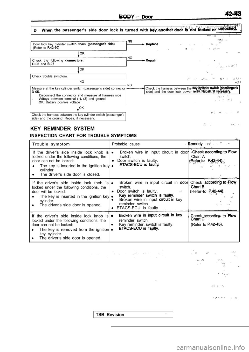
the passenger’s side door lock is turned with
NGDoor lock key cylinder SW(Refer to . .
NGCheck the following Repair.
and .
OK
Check trouble symptom.. .
NGN GMeasure at the key cylinder switch (passenger’s sid e) connector Check the harness between the side) and the door lock power .
Disconnect the connector and measure at harness sid e. between terminal (3) and groundOK:Battery positive voltage .
OK
Check the harness between the key cylinder switch (
passenger’s
side) and the ground. Repair, if necessary.
KEY REMINDER SYSTEM
INSPECTION CHART FOR TROUBLE SYMPTOMS
T r o u b l e s y m p t o m
Probable cause
If the driver’s side inside lock knob is lBroken wire in input circuit in door
locked under the following conditions, the switch.
Chart A
door can not be locked:l Door switch is faulty.
lThe key is inserted in the ignition key l
cylinder..
lThe driver’s side door is closed.
If the driver’s side inside lock knob ‘is lBroken wire in input circuit in Check
locked under the following conditions, the
switch.
door will be locked:l
Door switch is faulty.(Refer-to
lThe key is inserted in the ignition key l
cylinder.l
Broken wire in input in key
lThe driver’s side door is opened.reminder switch.l ETACS-ECU is faulty
If the driver’s side inside lock knob is
Check accordingto
locked under the following conditions, the reminder switch.
door can not be locked:lKey reminder. switch is faulty.(Refer to
lThe key is removed from the ignition l
key cylinder.lThe driver’s side door is opened.
TSB Revision